2003 Oldsmobile Alero fuel
[x] Cancel search: fuelPage 2 of 354

The 2003 Oldsmobile Alero Owner Manual a
Seats and Restraint Systems ........................... 1-1
Front Seats
............................................... 1-2
Rear Seats
............................................... 1-8
Safety Belts
.............................................. 1-9
Child Restraints
....................................... 1-32
Supplemental Restraint System (SRS)
...................................... 1-53
Restraint System Check
............................ 1-60
Keys
........................................................ 2-2
Doors and Locks
....................................... 2-7
Windows
................................................. 2-1 4
Theft-Deterrent Systems ............................ 2-1 6
Starting and Operating Your Vehicle
........... 2-17
Mirrors
.................................................... 2-32
Siorage Areas
......................................... 2-34
Sunroof .................................................. 2-35
Instrument Panel Overview
.......................... 3-4
Climate Controls
...................................... 3-1 9
.w .arning Lights, Gages and indicators ......... 3-23
Audio System(s) ....................................... 3-38
Features and Controls
..................................... 2-1
Instrument Panel
............................................. 3-1 Driving Your Vehicle
....................................... 4-1
Your Driving, the Road, and Your Vehicle
..... 4-2
Towing
................................................... 4-31
Service
..................................................... 5-3
Fuel ......................................................... 5-5
Checking Things Under
the
Hood ............................................... 5-9
Headlamp Aiming
..................................... 5-47
Bulb Replacement .................................... 5-49
Windshield Wiper Blade Replacement
......... 5-52
Tires
...................................................... 5-53
Appearance Care
..................................... 5-72
Vehicle Identification
................................. 5-80
Electrical System
...................................... 5-81
Zapai;iiit=s at-tii ~J~LIIIL~LIUI I> 5-w~
Normal Maintenance Replacement Parts ...... 5-88
Maintenance Schedule ........................... ... 6-1
Maintenance Schedule
................................ 6-2
Customer Assistance Information
.................... 7-1
Customer
Assistance iniorrnation .................. 7-2
Index ................................................................. 1
Service
and Appearance Care
.......................... 5-1
n.- - -:I: - -1: - .- - .....................
Page 85 of 354
Theft-Deterrent Systems
Vehicle theft is big business, especially in some cities.
Although your vehicle has a number of theft-deterrent
features, we know that nothing we put on it can make
it
impossible to steal.
Passlock@
Your vehicle has the Passlock@ theft-deterrent system.
Passlock@ is a passive theft-deterrent system.
Passlock@ enables fuel
if the ignition lock cylinder has
not been tampered with.
During normal operation, the SECURITY light will go
off
approximately five seconds after the ignition key is
turned to
ON and the engine is started.
After attempting to start the engine,
if the SECURITY
light flashes or stays on, wait ten minutes with the key in
ON until the light goes off. Then turn the ignition to
OFF before attempting to start the engine again.
See
Roadside Assistance Program on page 7-5 for
more information.
2-1 6
Page 90 of 354
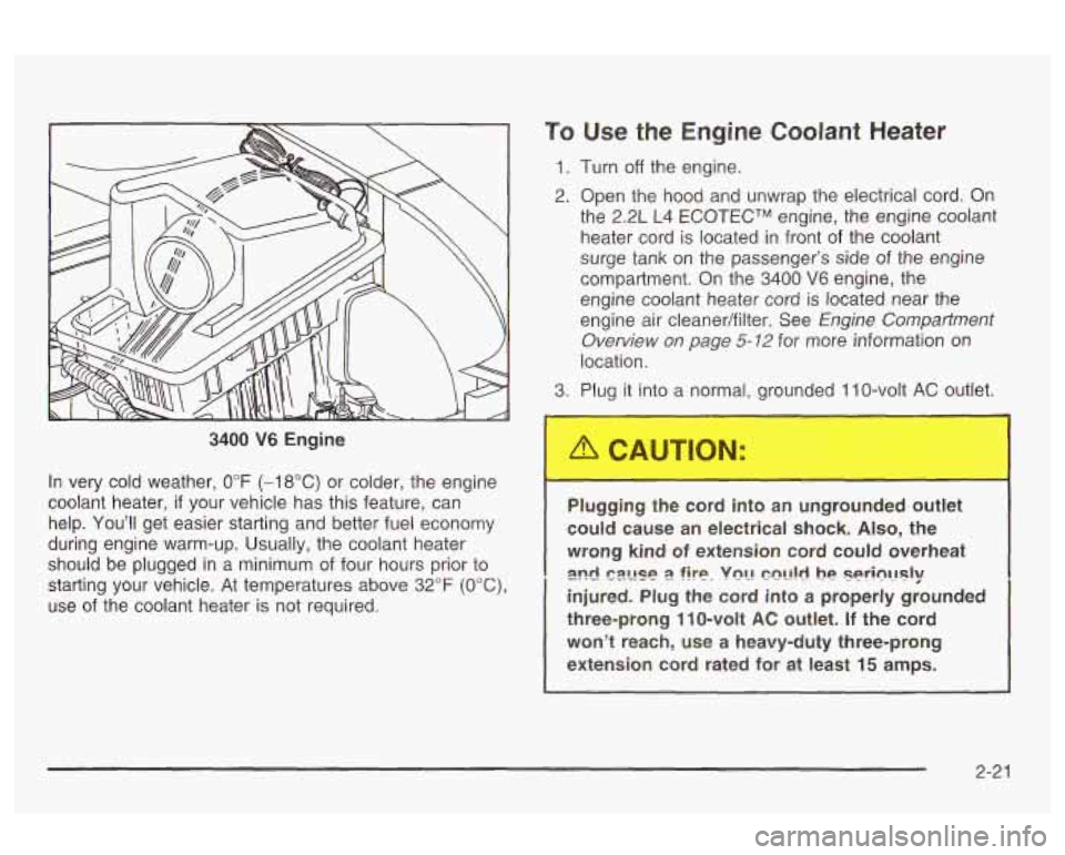
3400 V6 Engine
In very cold weather,
0°F (-18°C) or colder, the engine
coolant heater,
if your vehicle has this feature, can
help. You'll get easier starting and better fuel economy
during engine warm-up. Usually, the coolant heater
should be plugged in a minimum of four hours prior to
starting your vehicle. At temperatures above
32°F (OOC),
use of the coolant heater is not required.
To Use the Engine Coolant Heater
1. Turn off the engine.
2. Open the hood and unwrap the electrical cord. On
the 2.2L L4
ECOTECTM engine, the engine coolant
heater cord is located in front of the coolant
surge tank on the passenger's side
of the engine
compartment. On the
3400 V6 engine, the
engine coolant heater cord is located near the
engine air cleaner/filter. See
Engine Compartment
Overview on page
5-12 for more information on
location.
3. Plug it into a normal, grounded 1 IO-volt AC outlet.
Plugging the cord into an ungrounded ou' t
could cause an electrical shock. Also, the
wrong kind
of extension cord could overheat
injured. Plug the cord into a properly grounded
three-prong
11 0-volt AC outlet. If the cord
won't reach, use a heavy-duty three-prong
extension cord rated for at least
15 amps.
2nd !-?z!Jse 2 fire. VQL! C?!!!,! he Seri~IJsly
2-2 1
Page 93 of 354
Notice: If your vehicle seems to start up rather
slowly, or if
it seems not to shift gears as you go
faster, something may be wrong with a transaxle system sensor. If you drive very far that way, your
vehicle can be damaged.
So, if this happens,
have your vehicle serviced right away. Until then,
you can use SECOND
(2) when you are driving
less than
35 mph (55 kmh) and AUTOMATIC
OVERDRIVE (D) for higher speeds.
THIRD
(3): This position is also used for normal driving.
However, it offers more power and lower fuel economy
than AUTOMATIC OVERDRIVE (D). Here are some
times you might choose THIRD
(3) instead of
AUTOMATIC OVERDRIVE (D):
When driving on hilly, winding roads.
When towing a trailer, so there is less shifting
When going down a steep hill.
between
gears. SECOND
(2): This
position gives you more power but
lower fuel economy.
You can use SECOND (2) on
hills. It can help control your speed as you go down
steep mountain roads, but then you would also want to
use your brakes off and on.
Notice: Don’t drive in SECOND (2) for more than
25 miles (40 km), or at speeds over 55 mph
(90 km/h), or you can damage your transaxle. Use
THIRD
(3) or AUTOMATIC OVERDRIVE (D) as
much as possible. Don’t shift into SECOND
(2)
unless you are going slower than 65 mph (105 kdh)
or you can damage your engine.
FIRST
(1): This position gives you even more power
but lower fuel economy than SECOND
(2). You can use
it on very steep hills, or in deep snow or mud. If the
shift lever is put in FIRST
(I), the transaxle won’t shift
into first gear until the vehicle is going slowly enough.
Notice: If your front wheels won’t turn, don’t
try to drive. This might happen if you were stuck
in
very deep sand or mud or were up against a solid
object. You could damage your transaxle. Also,
if you stop when going uphill, don’t hold your
vehicle there with only the accelerator pedal. This
could overheat and damage the transaxle. Use your
brakes to hold your vehicle
in position on a hill.
2-24
Page 95 of 354
Shift Speeds
I
If you skip a gear when you downshift, you
could lose control of your vehicle. You could
injure yourself
or others. Don’t shift down
more than one gear at a time when you
downshift.
Up-Shift Light
Parking Brake
ii
SHIFT
If you have a manual
transaxle, you may have a
SHIFT light located on
the instrument panel
cluster. This light will show
you when to shift to the
next higher gear for
the best fuel economy.
When this light comes on, you can shift to the next
higher gear
if the weather, road and traffic conditions
permit. For the best fuel economy, accelerate slowly and
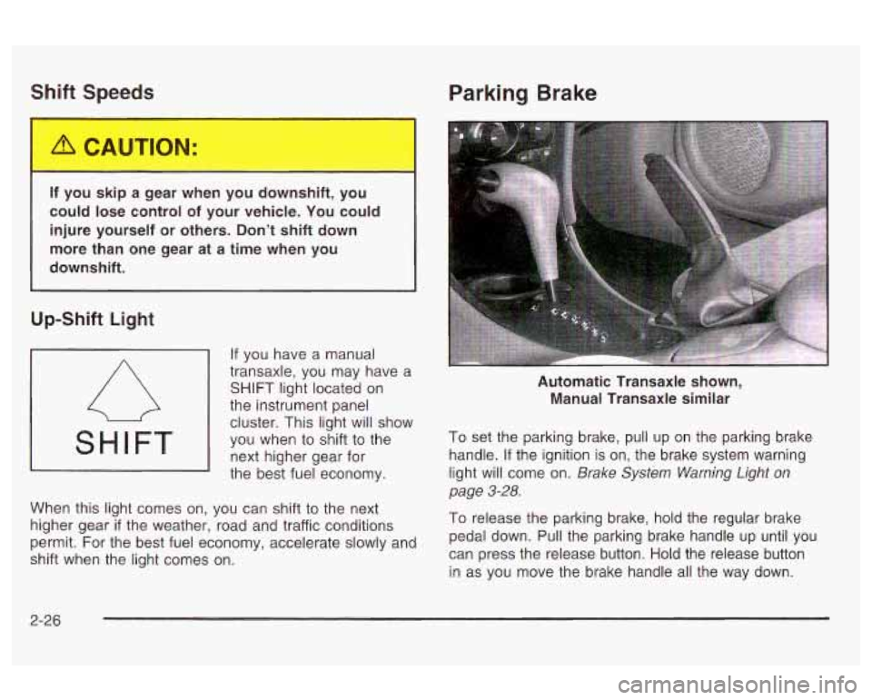
shift when the light comes on. Automatic Transaxle shown,
Manual Transaxle similar
To set the parking brake, pull up on the parking brake
handle.
If the ignition is on, the brake system warning
light will come on.
Brake System Warning Light on
page
3-28.
To release the parking brake, hold the regular brake
pedal down. Pull the parking brake handle up until you
can press the release button.
Hold the release button
in as you move the brake handle all the way down.
2-26
Page 106 of 354
Section 3 Instrument Panel
Instrument Panel Overview ............................... 3.4
Hazard Warning Flashers
.......... .............. 3.6
Other Warning Devices
................................... 3.6
Horn
............................................................. 3.6
Tilt Wheel
..................................................... 3.7
Turn SignaVMultifunction Lever
......................... 3.7
Exterior Lamps
............................................. 3.13
Interior Lamps
.............................................. 3.16
Accessory Power Outlets
............................... 3.17
Ashtrays and Cigarette Lighter
........................ 3.18
Climate Controls
........................................... -3-1 9
Climate Control System
................................. 3.19
Outlet Adjustment
......................................... 3.22
Warning Lights, Gages and Indicators
............. 3.23
Instrument Panel Cluster
................................ 3.24
Speedometer and Odometer
........................... 3.25
Tachometer
................................................. 3.25
Safety Belt Reminder Light
............................. 3.26
Air
Eag Reauiness iighi 3-LW
Charging System Light .................................. 3.27
fi cln ................................
Up-Shift Light .............................. .......... 3-28
Brake System Warning Light
........, .......... 3-28
Anti-Lock Brake System
Enhanced Traction System
Enhanced Traction System
Warning
bight
........................................ 3-29
Warning Light
........................................... 3-29
Active Light
.............................................. 3-30
Engine Coolant Temperature Gage
.................. 3-31
Low Coolant Warning Light
............................ 3-31
Malfunction Indicator Lamp
............................. 3-31
Oil Pressure Light
......................................... 3-34
Low Oil Level Light
....................................... 3-35
Security Light
............................................... 3-36
Cruise Control Light
...................................... 3-36
%??:ice ‘!ehic!n see!? Light ........................... ._ 2-36
Fuel Gage ................................................... 3-37
Change Engine
Oil Light
................................ 3-35
Low Washer Fluid Warning Light
..................... 3-36
3-
1
Page 129 of 354
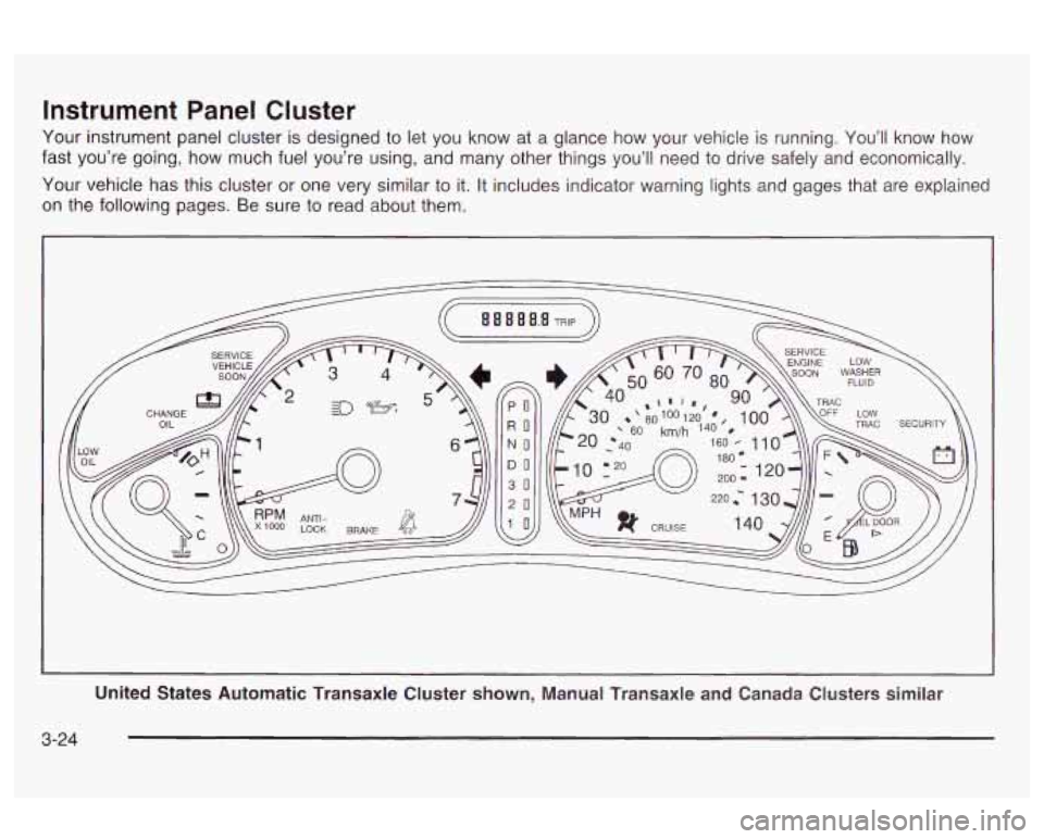
Instrument Panel Cluster
Your instrument panel cluster is designed to let you know at a glance how your vehicle is running. You’ll know how
fast you’re going, how much fuel you’re using, and many other things you’ll need to drive safely and economically.
Your vehicle has this cluster
or one very similar to it. It includes indicator warning lights and gages that are explained
on the following pages. Be sure to read about them.
PO
RO
NO
DO
30
20
United States Automatic Transaxle Cluster shown, Manual Transaxle and Canada Clusters similar
3-24
Page 136 of 354

Engine Coolant Temperature Gage
This gage shows the engine coolant
temperature.
if the gage
pointer moves into the red
area, the light comes
on and you hear a chime,
your engine
is too hot.
It means that your engine
coolant has overheated.
See
Engine Overheating on page 5-26.
Low Coolant Warning Light
1
This light comes on
briefly when you turn your
ignition on.
!f this !ight comes on and stays on and you hear a
chime, the coolant level in your vehicle is low.
See
Engine Coolant on page 5-23. If the light is on along
with an overheat warning, you may have a
serious overheating problem. See
Engine Coolant
Temperature Gage on page 3-31
listed previously.
Notice: Damage to your engine from neglected
coolant problems can be costly and is not covered
by your warranty.
See
Engine Overheating on page 5-26 for information
on what
to do. Your vehicle should be serviced as soon
as possible.
Malfunction Indicator Lamp
Service Engine Soon Light in the
United States
or Check Engine Light in
Canada
17
SERVICE
ENGINE
SOON
II I I I
United States Canada
Your vehicle is equipped with a computer which
monitors operation of the fuel, ignition and emission
control systems.
3-3 1