Page 3668 of 4179
SC-24
STARTING SYSTEM
Trouble DiagnosesEKS0031I
If any malfunction is found, immediately disconnect the battery cable from the negative terminal.
SEL761W
Page 3669 of 4179

STARTING SYSTEM
SC-25
C
D
E
F
G
H
I
J
L
MA
B
SC
Removal and Installation EKS0031J
REMOVAL
M/T models
1. Disconnect the battery cable from the negative terminal.
2. Remove air duct. Refer to EM-15, "
AIR CLEANER AND AIR
DUCT" (QR engine models) or EM-133, "AIR CLEANER AND
AIR DUCT" (YD engine models).
3. Disconnect S connector and B terminal from starter motor.
4. Remove starter motor mounting bolts.
5. Remove starter motor upward.
A/T models
1. Disconnect the battery cable from the negative terminal.
2. Remove air duct and air cleaner assembly. Refer to EM-15, "
AIR
CLEANER AND AIR DUCT" (QR engine models) or EM-133,
"AIR CLEANER AND AIR DUCT" (YD engine models).
3. Remove A/T selector cable and harness from bracket.
4. Disconnect S connector and B terminal from starter motor.
5. Remove starter motor upward.
INSTALLATION
Installation is the reverse order of removal.
QR engine models (M/T)
QR engine models (A/T)
YD22 engine models
PKIA2741E
PKIA2742E
B terminal nut:
:9.81 - 11.8 N·m (1.0 - 1.2 kg-m, 87 - 112 in-lb)
Starter motor mounting bolt:
: 98.1 - 127.0 N·m (10.0 - 13.0 kg-m, 73 - 94 ft-lb)
B terminal nut:
: 7.3 - 9.8 N·m (0.75 - 1.00 kg-m, 65 - 87 in-lb)
Starter motor mounting bolt:
Upper side:
: 41.2 - 52.0 N·m (4.2 - 5.3 kg-m, 31 - 38 ft - lb)
Lower side:
: 98.1 - 127.0 N·m (10.0 -13.0 kg-m, 73 -94 ft-lb)
B terminal nut:
: 9.81 - 11.8 N·m (1.0 - 1.2 kg-m, 87 - 112 in-lb)
Starter motor mounting bolt:
: 41.2 - 52.0 N·m (4.2 - 5.3 kg-m, 31 - 38 ft-lb)
Page 3670 of 4179
SC-26
STARTING SYSTEM
Disassembly and Assembly EKS0031K
QR ENGINE MODELS
M/T Models
1. Sleeve bearing 2. Gear case 3. Stopper clip
4. Pinion stopper 5. Pinion assembly 6. Internal gear
7. Plate 8. Packing 9. Adjusting plate
10. Magnetic switch assembly 11. Planetary gear 12. Ball
13. Packing 14. Yoke 15. Armature
16. Brush holder assembly 17. Rear bearing 18. Rear cover
Through-bolt:
: 4.1 - 7.4 N·m (0.45 - 0.72 kg-m, 39.1 - 62.5 in-lb)
PKIA0464E
Page 3671 of 4179
STARTING SYSTEM
SC-27
C
D
E
F
G
H
I
J
L
MA
B
SC
A/T Models
1. Pinion stopper clip 2. Pinion stopper 3. Pinion
4. Pinion spring 5. Gear case assembly 6. Shift lever set
7. Dust cover kit 8. Magnetic switch assembly 9. Clutch assembly
10. E-ring 11. Thrust washer 12. Center bracket (P)
13. Packing 14. Planetary gear 15. Internal gear
16. Center bracket (A) 17. Yoke assembly 18. Armature assembly
19. Brush holder assembly 20. Brush (-) 21. Brush spring
22. Thrust washer 23. Rear cover assembly
Through-bolt:
: 4.9 - 6.4 N·m (0.50 - 0.65 kg-m, 43.4 - 56.4 in-lb)
PKIA0466E
Page 3672 of 4179
SC-28
STARTING SYSTEM
YD ENGINE MODELS
1. Stopper clip 2. Pinion stopper 3. Pinion
4. Spring 5. Gear case 6. Plate
7. Packing 8. Adjusting plate 9. Magnetic switch assembly
10. Snap ring 11. Retainer ring 12. Over running clutch
13. Internal gear 14. Planetary gear 15. Ball
16. Packing 17. Cover 18. Yoke
19. Armature 20. Washer 21. Rear bearing
22. Brush holder assembly 23. Brush spring 24. Brush (-)
25. Rear cover
Through-bolt:
: 5.6 - 10.4 N·m (0.57 - 1.06 kg-m, 49.5 - 92.0 in-lb)
PKIA0465E
Page 3673 of 4179

STARTING SYSTEM
SC-29
C
D
E
F
G
H
I
J
L
MA
B
SC
InspectionEKS0031L
MAGNETIC SWITCH CHECK
�Before starting to check, disconnect the battery cable from the negative terminal.
�Disconnect “M” terminal of starter motor.
1. Continuity test (between “S” terminal and switch body).
�No continuity... Replace.
2. Continuity test (between “S” terminal and “M” terminal).
�No continuity... Replace.
PINION/CLUTCH CHECK
1. Inspect pinion teeth.
�Replace pinion if teeth are worn or damaged. (Also check
condition of ring gear teeth.)
2. Inspect reduction gear teeth (If equipped).
�Replace reduction gear if teeth are worn or damaged. (Also
check condition of armature shaft gear teeth.)
3. Check to see if pinion locks in one direction and rotates
smoothly in the opposite direction.
�If it locks or rotates in both directions, or unusual resistance is
evident.... Replace.
BRUSH CHECK
Brush
Check wear of brush.
�Excessive wear... Replace.
SEL555E
SEL556E
MEL139L
Wear limit length : Refer to SDS. SC-34, "Starter" .
SEL014Z
Page 3674 of 4179
SC-30
STARTING SYSTEM
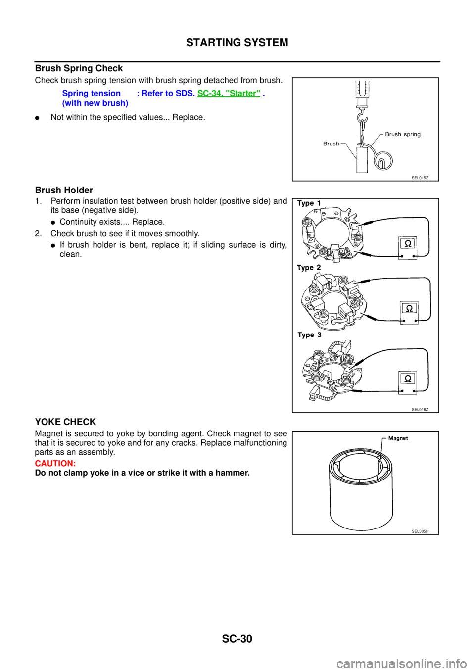
Brush Spring Check
Check brush spring tension with brush spring detached from brush.
�Not within the specified values... Replace.
Brush Holder
1. Perform insulation test between brush holder (positive side) and
its base (negative side).
�Continuity exists.... Replace.
2. Check brush to see if it moves smoothly.
�If brush holder is bent, replace it; if sliding surface is dirty,
clean.
YOKE CHECK
Magnet is secured to yoke by bonding agent. Check magnet to see
that it is secured to yoke and for any cracks. Replace malfunctioning
parts as an assembly.
CAUTION:
Do not clamp yoke in a vice or strike it with a hammer.Spring tension
(with new brush): Refer to SDS. SC-34, "
Starter" .
SEL015Z
SEL016Z
SEL305H
Page 3675 of 4179
STARTING SYSTEM
SC-31
C
D
E
F
G
H
I
J
L
MA
B
SC
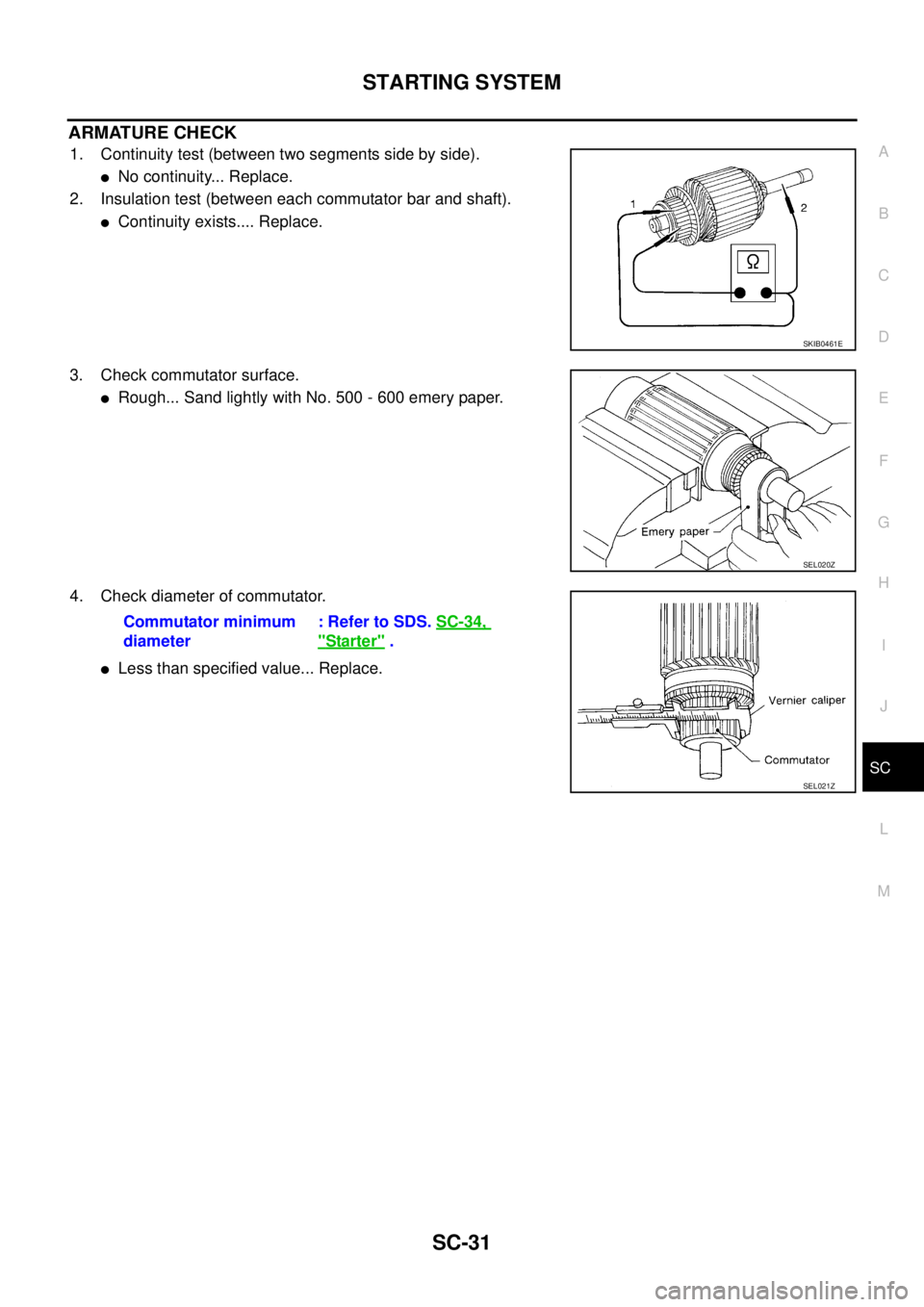
ARMATURE CHECK
1. Continuity test (between two segments side by side).
�No continuity... Replace.
2. Insulation test (between each commutator bar and shaft).
�Continuity exists.... Replace.
3. Check commutator surface.
�Rough... Sand lightly with No. 500 - 600 emery paper.
4. Check diameter of commutator.
�Less than specified value... Replace.
SKIB0461E
SEL020Z
Commutator minimum
diameter: Refer to SDS. SC-34,
"Starter" .
SEL021Z