Page 2628 of 4179
TF-52
4WD CONTROL UNIT
4WD CONTROL UNITPFP:41650
Removal and InstallationEDS001W4
REMOVAL
1. Remove cluster lid “A”. Refer to IP-11, "Removal and Installation" .
2. Remove front speaker grille. Refer to IP-11, "
Removal and Installation" .
3. Remove driver box. Refer to IP-11, "
Removal and Installation" .
4. Disconnect 4WD control unit connector.
5. Remove 4WD control unit.
INSTALLATION
Install in the reverse order of removal.
SDIA1881E
Page 2715 of 4179

RAX-1
REAR AXLE
D DRIVELINE/AXLE
CONTENTS
C
E
F
G
H
I
J
K
L
M
SECTION
A
B
RAX
REAR AXLE
PRECAUTIONS .......................................................... 2
Caution ..................................................................... 2
PREPARATION ........................................................... 3
Special Service Tools (SST) ..................................... 3
NOISE, VIBRATION AND HARSHNESS (NVH)
TROUBLESHOOTING ................................................ 5
NVH Troubleshooting Chart ..................................... 5
WHEEL HUB (4WD) ................................................... 6
On-Vehicle Inspection .............................................. 6
REAR WHEEL BEARING ..................................... 6
Removal and Installation .......................................... 6
REMOVAL ............................................................. 7
INSTALLATION ..................................................... 7
Disassembly and Assembly ..................................... 7
DISASSEMBLY ..................................................... 7
INSPECTION AFTER DISASSEMBLY ................. 8
ASSEMBLY ........................................................... 8REAR DRIVE SHAFT ............................................... 10
Removal and Installation ........................................ 10
REMOVAL ........................................................... 10
INSPECTION AFTER REMOVAL ....................... 10
INSTALLATION ................................................... 10
Disassembly and Assembly .................................... 11
DISASSEMBLY ................................................... 11
INSPECTION AFTER DISASSEMBLY ................ 12
ASSEMBLY ......................................................... 12
SERVICE DATA AND SPECIFICATIONS (SDS) ...... 15
Wheel Bearing ........................................................ 15
Drive Shaft .............................................................. 15
Page 2720 of 4179
RAX-6
WHEEL HUB (4WD)
WHEEL HUB (4WD)PFP:43202
On-Vehicle InspectionEDS00065
Inspect to check that there is no excessive play, cracking, wear, or other damage to rear axle.
�Turn rear wheels (left/right) and check the play.
REAR WHEEL BEARING
With vehicle raised, inspect the following.
�Move wheel hub in the axial direction by hand. Check that there is no looseness of rear wheel bearing.
�Rotate wheel hub and check that there is no unusual noise or other irregular condition. If there are any
irregular condition, replace wheel bearing.
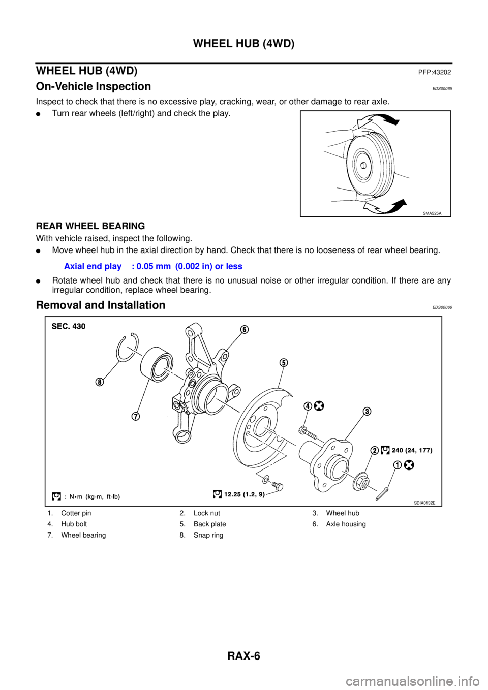
Removal and InstallationEDS00066
SMA525A
Axial end play : 0.05 mm (0.002 in) or less
1. Cotter pin 2. Lock nut 3. Wheel hub
4. Hub bolt 5. Back plate 6. Axle housing
7. Wheel bearing 8. Snap ring
SDIA0132E
Page 2721 of 4179

RAX-7
C
E
F
G
H
I
J
K
L
MA
B
RAX
REMOVAL
1. Remove tyre.
2. Remove wheel hub lock nut.
CAUTION:
Discard the old hub lock nut; replace with new one.
3. Remove brake caliper from axle")
WHEEL HUB (4WD)
RAX-7
C
E
F
G
H
I
J
K
L
MA
B
RAX
REMOVAL
1. Remove tyre.
2. Remove wheel hub lock nut.
CAUTION:
Discard the old hub lock nut; replace with new one.
3. Remove brake caliper from axle housing and hang it up some-
where.
CAUTION:
Avoid depressing the brake pedal while the brake caliper is
removed.
4. Remove disc rotor and parking brake assembly from back plate
and axle housing.
5. Remove wheel sensor from axle housing.
6. Remove axle housing from strut.
7. Remove nut and bolt from axle housing side of radius rod.
8. Remove nuts and bolts from axle housing side of front and rear parallel link. Remove axle housing from
vehicle.
INSTALLATION
�Refer to component parts drawing for tightening torque. For installation, follow removal procedure in
reverse order.
Disassembly and AssemblyEDS00067
DISASSEMBLY
1. Set axle housing on bench vise. As shown in the figure, use
attachment (SST) and sliding hammer (SST) to remove wheel
hub and bearing assembly from axle housing.
CAUTION:
When placing onto bench vise, be careful not to damage
strut mounting surface of steering knuckle. Use an alumi-
num plate or another suitable tool.
2. Use a bearing replacer (suitable tool), puller (suitable tool), and
drift (SST) to remove inner race of outer-wheel bearing from
wheel hub.
3. Remove back plate installation bolt and anchor block. Remove
back plate from axle housing. Refer to PB-4, "
Components"
4. Use a flat-bladed screwdriver or similar tool to remove snap ring.
SRA711A
FAC0104D
SDIA0154E
Page 2722 of 4179

5. Use a drift (SST) to remove wheel bearing from axle housing.
INSPECTION AFTER DISASSEMBLY
Wheel Hub
�Inspect wheel hub for deformation, cracks, and other damage. If any irre")
RAX-8
WHEEL HUB (4WD)
5. Use a drift (SST) to remove wheel bearing from axle housing.
INSPECTION AFTER DISASSEMBLY
Wheel Hub
�Inspect wheel hub for deformation, cracks, and other damage. If any irregular conditions are found,
replace wheel hub.
Axle Housing
�Inspect axle housing for deformation, cracks, and other damage. If any irregular conditions are found,
replace axle housing.
Snap Ring
�Check snap ring for deformation, cracks, and other damage. If any irregular conditions are found, replace
snap ring.
ASSEMBLY
1. Use a drift (SST) to press fit wheel bearing into axle housing.
CAUTION:
Discard the old wheel bearing; replace with a new one.
2. Use a flat-bladed screwdriver or similar tool to install the snap
ring.
3. Install back plate and anchor block onto axle housing. Refer to
PB-4, "
Components" .
4. Use a drift (SST) to install wheel hub onto axle housing.
5. After completing step 4, apply an additional load of 49,030 N
(5,000 kg, 11,025 lb). Rotate axle housing in forward and
reverse directions 10 times each to ensure a good fit.
6. Place a spring balance at the point where the strut is joined (upper side bolt hole) and measure rotating
torque when spring is pulled at a speed of 8 -12 rpm. Refer to the RAX-15, "
Wheel Bearing" item.
NOTE:
If a load of 49,030 N (5,000 kg, 11,025 lb) cannot be applied:
�Install to drive shaft and tighten wheel hub lock nut to specified torque. Rotate in forward and reverse
direction 10 times each to ensure a good fit.
�At a rotating speed of 8 - 12 rpm, place a spring balance on hub bolt and measure rotating torque.
SDIA0155E
SDIA1349E
SDIA0157E
Rotating torque : 1.96 N·m (0.20 kg-m, 17 in-lb) or less
Spring balance reading : 12.8 N (1.30 kg, 2.87 lb) or less
Page 2723 of 4179
WHEEL HUB (4WD)
RAX-9
C
E
F
G
H
I
J
K
L
MA
B
RAX
Rotating torque : 1.126 N·m (0.11 kg-m, 10 in-lb)
Spring balance reading : 19.70 N (2.01 kg, 4.43 lb)
Page 2743 of 4179

FSU-13
C
D
F
G
H
I
J
K
L
MA
B
FSU
SERVICE DATA AND SPECIFICATIONS (SDS)PFP:00030
General SpecificationEES000J6
Wheel Alignment (Unladen)EES00079
: Fuel, radiato")
SERVICE DATA AND SPECIFICATIONS (SDS)
FSU-13
C
D
F
G
H
I
J
K
L
MA
B
FSU
SERVICE DATA AND SPECIFICATIONS (SDS)PFP:00030
General SpecificationEES000J6
Wheel Alignment (Unladen)EES00079
: Fuel, radiator coolant and engine oil full. Spare tire, jack, hand tools and mats in designated positions.
Ball JointEES0007A
Wheelarch Height (Unladen)EES000J9
Suspension type Independent Macpherson strut
Shock absorber type Double-acting hydraulic
Stabilizer bar Standard equipment
Drive type4WD
Engine type QR20DE and QR25DE YD22DDTi
Camber
Degree minute (Decimal degree)Minimum – 0°54′ (– 0.9°)
Nominal – 0°24′ (– 0.4°)
Maximum 0°36′ (0.6°)
Left and right difference 45′ (0.75°)
Caster
Degree minute (Decimal degree)Minimum 1°42′ (1.7°)
Nominal 2°27′ (2.45°)
Maximum 3°12′ (3.2°)
Left and right difference 45′ (0.75°)
Kingpin offset
Degree minute (Decimal degree)Minimum 12°06′ (12.1°)
Nominal 13°30′ (13.5°)
Maximum 13°36′ (13.6°)
Total toe-in
Distance (A - B)Minimum 0 mm (0 in)
Nominal 1 mm (0.04 in)
Maximum 2 mm (0.08 in)
Wheel turning angel Refer to PS-42, "
Steering Angle" .
Swing torque 0.5 - 3.4 N·m (0.05 - 0.35 kg-m, 5 - 30 in-lb)
Measurement on spring balance (cotter pinhole position) 7.94 - 53.97 N (0.81 - 5.50 kg, 1.79 - 12.2 lb)
Turning torque 0.5 - 3.4 N·m (0.05 - 0.35 kg-m, 5 - 30 in-lb)
Axial endplay 0.1 mm (0.004 in) or less
Applied model QR20DE and QR25DE engine YD22DDTi engine
215/70R15 and 215/65R16 215/65R16
Front (Hf) 773 mm (30.43 in) 771 mm (30.35 in)
Rear (Hr) 786 mm (30.94 in) 785 mm (30.91 in)
SFA818A
Page 2822 of 4179
![NISSAN X-TRAIL 2003 Service Repair Manual BRC-8
[ABS]
CAN COMMUNICATION
CAN COMMUNICATIONPFP:23710
System DescriptionEFS0055R
CAN (Controller Area Network) is a serial communication line for real time application. It is an on-vehicle mul-
t](/manual-img/5/57404/w960_57404-2821.png "NISSAN X-TRAIL 2003 Service Repair Manual BRC-8
[ABS]
CAN COMMUNICATION
CAN COMMUNICATIONPFP:23710
System DescriptionEFS0055R
CAN (Controller Area Network) is a serial communication line for real time application. It is an on-vehicle mul-
t")
BRC-8
[ABS]
CAN COMMUNICATION
CAN COMMUNICATIONPFP:23710
System DescriptionEFS0055R
CAN (Controller Area Network) is a serial communication line for real time application. It is an on-vehicle mul-
tiplex communication line with high data communication speed and excellent error detection ability. Many elec-
tronic control units are equipped onto a vehicle, and each control unit shares information and links with other
control units during operation (not independent). In CAN communication, control units are connected with 2
communication lines (CAN H line, CAN L line) allowing a high rate of information transmission with less wiring.
Each control unit transmits/receives data but selectively reads required data only.
CAN Communication UnitEFS0055W
×: Applicable
TYPE 1
System diagram
Body typeWagon
Axle4WD
Engine QR20DE/QR25DE QR25DE YD22DDTi QR25DE
Transmission M/T A/T M/T A/T
Brake control ABS ESP
CAN communication unit
ECM×××××
TCM××
ABS actuator and electric unit (control unit)××
ESP/TCS/ABS control unit×××
Steering angle sensor×××
4WD control unit×××××
Combination meter×××××
CAN communication typeBRC-8, "
TYPE
1"
BRC-9, "TYPE
2"BRC-55, "TYPE 3/TYPE4"BRC-56,
"TYPE 5"
PKIA6458E


RAX-9
C
E
F
G
H
I
J
K
L
MA
B
RAX
Rotating torque : 1.126 N·m (0.11 kg-m, 10 in-lb)
Spring balance reading : 19.70 N (2.01 kg, 4.43 lb)")