Page 3391 of 4179
REAR SEAT
SE-31
C
D
E
F
G
H
J
K
L
MA
B
SE
REAR SEATPFP:88300
Component Parts DrawingEIS000NR
STANDARD SEAT
PIIB0399E
1. Seatback board 2. Clip (C101) 3. TORX bolt
4. Inner hinge cover 5. Bolt 6. Seat lock
7. Seatback frame 8. Seatback pad 9. Seatback lock knob
10. Seatback lock knob finisher 11. Headrest 12. Headrest holder (free)
13. Headrest holder (locked) 14. Seatback trim 15. Screw
16. Seat lock protector 17. Rear back side bracket 18. Seat cushion lock
19. Seat cushion trim 20. Seat cushion pad 21. Seat cushion stay
22. Side hinge cover
Page 3392 of 4179
SE-32
REAR SEAT
SEAT WITH ARMREST
PIIB0400E
1. Seatback board finisher 2. Inner hinge cover 3. Screw
4. Seatback board 5. Clip (C101) 6. Seatback knob
7. Seatback knob finisher 8. Headrest 9. Headrest holder (free)
10. Headrest holder (locked) 11. Seatback pad 12. TORX bolt
13. Seat lock 14. Bolt 15. Seatback frame
16. Armrest bracket cover (RH) 17. Clip 18. Tonneau cover hook
19. Anchor bolt 20. Retractor cover 21. Seat belt (center)
22. Armrest 23. Armrest lid board 24. Seatback trim
25. Seat belt escutcheon 26. Seatback side bracket 27. Seat lock protector
28. Seat cushion pad 29. Seat cushion stay 30. Armrest bracket cover (LH)
31. Seat cushion lock 32. Side hinge cover 33. Seat cushion trim
Page 3394 of 4179
SE-34
REAR SEAT
REAR SEAT STRIKER (SIDE)
1. Remove luggage side lower finisher. Refer to EI-35, "Removal
and Installation" .
2. Remove bolts.
REAR SEAT CENTER BRACKET
1. Remove rear seatback.
2. Remove nuts and bolt.
REAR SEAT STRIKER (FLOOR)
1. Remove rear seat cushion.
2. Remove bolt.
Disassembly and AssemblyEIS000NT
REAR SEATBACK LOCK KNOB
Turn knob counterclockwise to remove.
ARMREST
1. Push armrest and lid forward. Remove clip.
2. Slide armrest and lid to the left, and pull out the pin from the hole on the seatback.
SIIA0254E
SIIA0255E
SIIA0256E
SIIA0259J
Page 3407 of 4179
PRECAUTIONS
ATC-11
C
D
E
F
G
H
I
K
L
MA
B
AT C
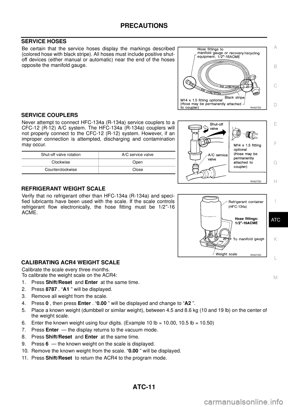
SERVICE HOSES
Be certain that the service hoses display the markings described
(colored hose with black stripe). All hoses must include positive shut-
off devices (either manual or automatic) near the end of the hoses
opposite the manifold gauge.
SERVICE COUPLERS
Never attempt to connect HFC-134a (R-134a) service couplers to a
CFC-12 (R-12) A/C system. The HFC-134a (R-134a) couplers will
not properly connect to the CFC-12 (R-12) system. However, if an
improper connection is attempted, discharging and contamination
may occur.
REFRIGERANT WEIGHT SCALE
Verify that no refrigerant other than HFC-134a (R-134a) and speci-
fied lubricants have been used with the scale. If the scale controls
refrigerant flow electronically, the hose fitting must be 1/2″-16
ACME.
CALIBRATING ACR4 WEIGHT SCALE
Calibrate the scale every three months.
To calibrate the weight scale on the ACR4:
1. Press Shift/Reset and Enter at the same time.
2. Press 8787 . “A1 ” will be displayed.
3. Remove all weight from the scale.
4. Press 0 , then press Enter . “0.00 ” will be displayed and change to “A2 ”.
5. Place a known weight (dumbbell or similar weight), between 4.5 and 8.6 kg (10 and 19 lb) on the center of
the weight scale.
6. Enter the known weight using four digits. (Example 10 lb = 10.00, 10.5 lb = 10.50)
7. Press Enter — the display returns to the vacuum mode.
8. Press Shift/Reset and Enter at the same time.
9. Press 6 — the known weight on the scale is displayed.
10. Remove the known weight from the scale. “0.00 ” will be displayed.
11 . P r e s s Shift/Reset to return the ACR4 to the program mode.
RHA272D
Shut-off valve rotation A/C service valve
Clockwise Open
Counterclockwise Close
RHA273D
RHA274D
Page 3464 of 4179
ATC-68
TROUBLE DIAGNOSIS
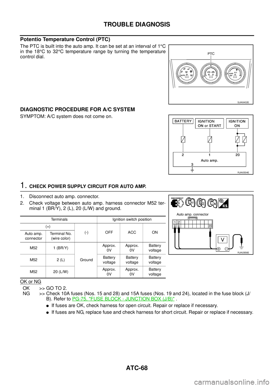
Potentio Temperature Control (PTC)
The PTC is built into the auto amp. It can be set at an interval of 1°C
in the 18°C to 32°C temperature range by turning the temperature
control dial.
DIAGNOSTIC PROCEDURE FOR A/C SYSTEM
SYMPTOM: A/C system does not come on.
1. CHECK POWER SUPPLY CIRCUIT FOR AUTO AMP.
1. Disconnect auto amp. connector.
2. Check voltage between auto amp. harness connector M52 ter-
minal 1 (BR/Y), 2 (L), 20 (L/W) and ground.
OK or NG
OK >> GO TO 2.
NG >> Check 10A fuses (Nos. 15 and 28) and 15A fuses (Nos. 19 and 24), located in the fuse block (J/
B). Refer to PG-75, "
FUSE BLOCK - JUNCTION BOX (J/B)" .
�If fuses are OK, check harness for open circuit. Repair or replace if necessary.
�If fuses are NG, replace fuse and check harness for short circuit. Repair or replace if necessary.
SJIA0402E
RJIA0504E
Terminals Ignition switch position
(+)
(-) OFF ACC ON
Auto amp.
connectorTe r m i n a l N o .
(wire color)
M52 1 (BR/Y)
GroundApprox.
0VApprox.
0VBattery
voltage
M52 2 (L)Battery
voltageBattery
voltageBattery
voltage
M52 20 (L/W)Approx.
0VApprox.
0VBattery
voltage
RJIA2856E
Page 3481 of 4179
TROUBLE DIAGNOSIS
ATC-85
C
D
E
F
G
H
I
K
L
MA
B
AT C
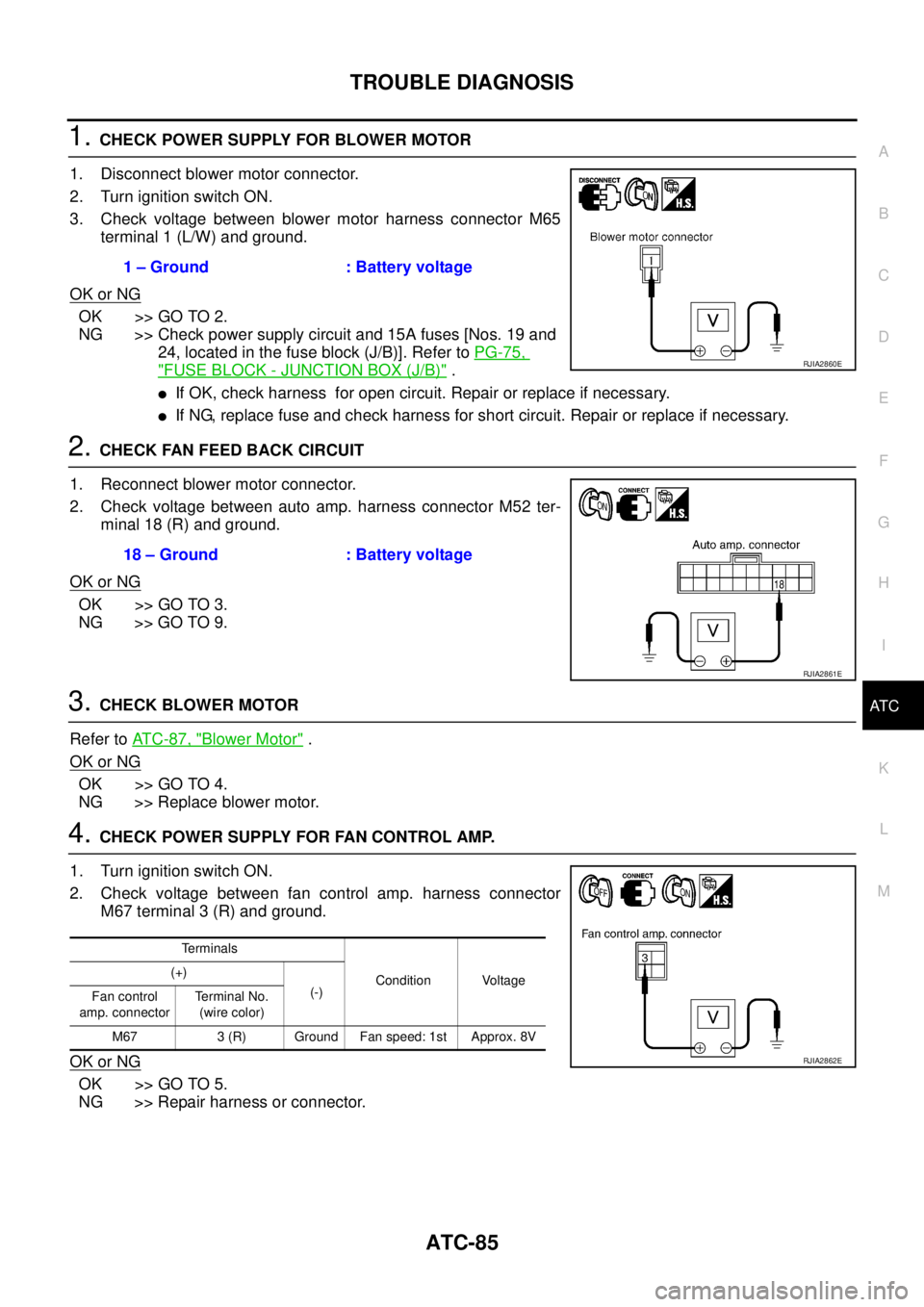
1. CHECK POWER SUPPLY FOR BLOWER MOTOR
1. Disconnect blower motor connector.
2. Turn ignition switch ON.
3. Check voltage between blower motor harness connector M65
terminal 1 (L/W) and ground.
OK or NG
OK >> GO TO 2.
NG >> Check power supply circuit and 15A fuses [Nos. 19 and
24, located in the fuse block (J/B)]. Refer to PG-75,
"FUSE BLOCK - JUNCTION BOX (J/B)" .
�If OK, check harness for open circuit. Repair or replace if necessary.
�If NG, replace fuse and check harness for short circuit. Repair or replace if necessary.
2. CHECK FAN FEED BACK CIRCUIT
1. Reconnect blower motor connector.
2. Check voltage between auto amp. harness connector M52 ter-
minal 18 (R) and ground.
OK or NG
OK >> GO TO 3.
NG >> GO TO 9.
3. CHECK BLOWER MOTOR
Refer to AT C - 8 7 , "
Blower Motor" .
OK or NG
OK >> GO TO 4.
NG >> Replace blower motor.
4. CHECK POWER SUPPLY FOR FAN CONTROL AMP.
1. Turn ignition switch ON.
2. Check voltage between fan control amp. harness connector
M67 terminal 3 (R) and ground.
OK or NG
OK >> GO TO 5.
NG >> Repair harness or connector.1 – Ground : Battery voltage
RJIA2860E
18 – Ground : Battery voltage
RJIA2861E
Terminals
Condition Voltage (+)
(-)
Fan control
amp. connectorTerminal No.
(wire color)
M67 3 (R) Ground Fan speed: 1st Approx. 8V
RJIA2862E
Page 3487 of 4179
TROUBLE DIAGNOSIS
ATC-91
C
D
E
F
G
H
I
K
L
MA
B
AT C
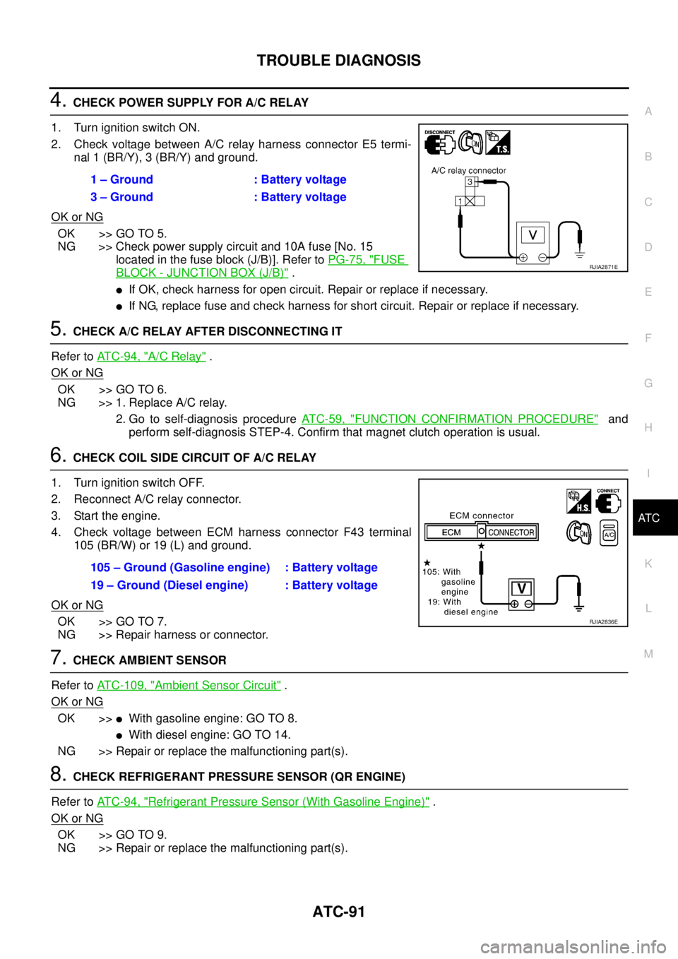
4. CHECK POWER SUPPLY FOR A/C RELAY
1. Turn ignition switch ON.
2. Check voltage between A/C relay harness connector E5 termi-
nal 1 (BR/Y), 3 (BR/Y) and ground.
OK or NG
OK >> GO TO 5.
NG >> Check power supply circuit and 10A fuse [No. 15
located in the fuse block (J/B)]. Refer to PG-75, "
FUSE
BLOCK - JUNCTION BOX (J/B)" .
�If OK, check harness for open circuit. Repair or replace if necessary.
�If NG, replace fuse and check harness for short circuit. Repair or replace if necessary.
5. CHECK A/C RELAY AFTER DISCONNECTING IT
Refer to AT C - 9 4 , "
A/C Relay" .
OK or NG
OK >> GO TO 6.
NG >> 1. Replace A/C relay.
2. Go to self-diagnosis procedure AT C - 5 9 , "
FUNCTION CONFIRMATION PROCEDURE" and
perform self-diagnosis STEP-4. Confirm that magnet clutch operation is usual.
6. CHECK COIL SIDE CIRCUIT OF A/C RELAY
1. Turn ignition switch OFF.
2. Reconnect A/C relay connector.
3. Start the engine.
4. Check voltage between ECM harness connector F43 terminal
105 (BR/W) or 19 (L) and ground.
OK or NG
OK >> GO TO 7.
NG >> Repair harness or connector.
7. CHECK AMBIENT SENSOR
Refer to ATC-109, "
Ambient Sensor Circuit" .
OK or NG
OK >>�With gasoline engine: GO TO 8.
�With diesel engine: GO TO 14.
NG >> Repair or replace the malfunctioning part(s).
8. CHECK REFRIGERANT PRESSURE SENSOR (QR ENGINE)
Refer to AT C - 9 4 , "
Refrigerant Pressure Sensor (With Gasoline Engine)" .
OK or NG
OK >> GO TO 9.
NG >> Repair or replace the malfunctioning part(s).1 – Ground : Battery voltage
3 – Ground : Battery voltage
RJIA2871E
105 – Ground (Gasoline engine) : Battery voltage
19 – Ground (Diesel engine) : Battery voltage
RJIA2836E
Page 3500 of 4179
ATC-104
TROUBLE DIAGNOSIS
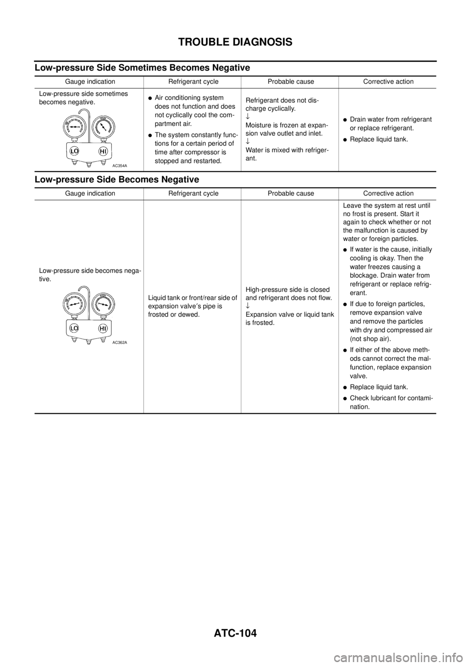
Low-pressure Side Sometimes Becomes Negative
Low-pressure Side Becomes Negative
Gauge indication Refrigerant cycle Probable cause Corrective action
Low-pressure side sometimes
becomes negative.
�Air conditioning system
does not function and does
not cyclically cool the com-
partment air.
�The system constantly func-
tions for a certain period of
time after compressor is
stopped and restarted.Refrigerant does not dis-
charge cyclically.
↓
Moisture is frozen at expan-
sion valve outlet and inlet.
↓
Water is mixed with refriger-
ant.
�Drain water from refrigerant
or replace refrigerant.
�Replace liquid tank.
AC354A
Gauge indication Refrigerant cycle Probable cause Corrective action
Low-pressure side becomes nega-
tive.
Liquid tank or front/rear side of
expansion valve′s pipe is
frosted or dewed.High-pressure side is closed
and refrigerant does not flow.
↓
Expansion valve or liquid tank
is frosted.Leave the system at rest until
no frost is present. Start it
again to check whether or not
the malfunction is caused by
water or foreign particles.
�If water is the cause, initially
cooling is okay. Then the
water freezes causing a
blockage. Drain water from
refrigerant or replace refrig-
erant.
�If due to foreign particles,
remove expansion valve
and remove the particles
with dry and compressed air
(not shop air).
�If either of the above meth-
ods cannot correct the mal-
function, replace expansion
valve.
�Replace liquid tank.
�Check lubricant for contami-
nation.
AC362A