Page 2940 of 4179
PS-4
FPREPARATION
FPREPARATIONPFP:00002
Special Service Tools (SST)EGS0004A
Tool number
Tool nameDescription
ST3127S000
Preload gaugeSteering torque check
ST27180001
Steering wheel pullerRemoval of steering wheel
KV48104400
Teflon ring correcting tool
a: 50 mm (1.97 in) dia.
b: 36 mm (1.42 in) dia.
C: 100 mm (3.94 in)Installing of rack Teflon ring
KV48103400
Torque adapterInspecting rotating torque
KV48103500
Hydraulic pressure gauge
KV48102500
Hydraulic pressure gauge adapter
1. KV48102500−01
(I-joint)
2. KV48102500−02
(Flare joint)
3. KV48102500−03
(Bolt)
4. KV48102500−04
(Washer)Measurement oil pump relief pressure
ST35300000
Drift
a: 45.1 mm (1.776 in) dia.
b: 59.0 mm (5.323 in) dia.Installing drive shaft seal
ZZA0806D
ZZA0819D
S-NT550
ZZA0824D
ZZA0839D
ZZA0881D
Page 2941 of 4179
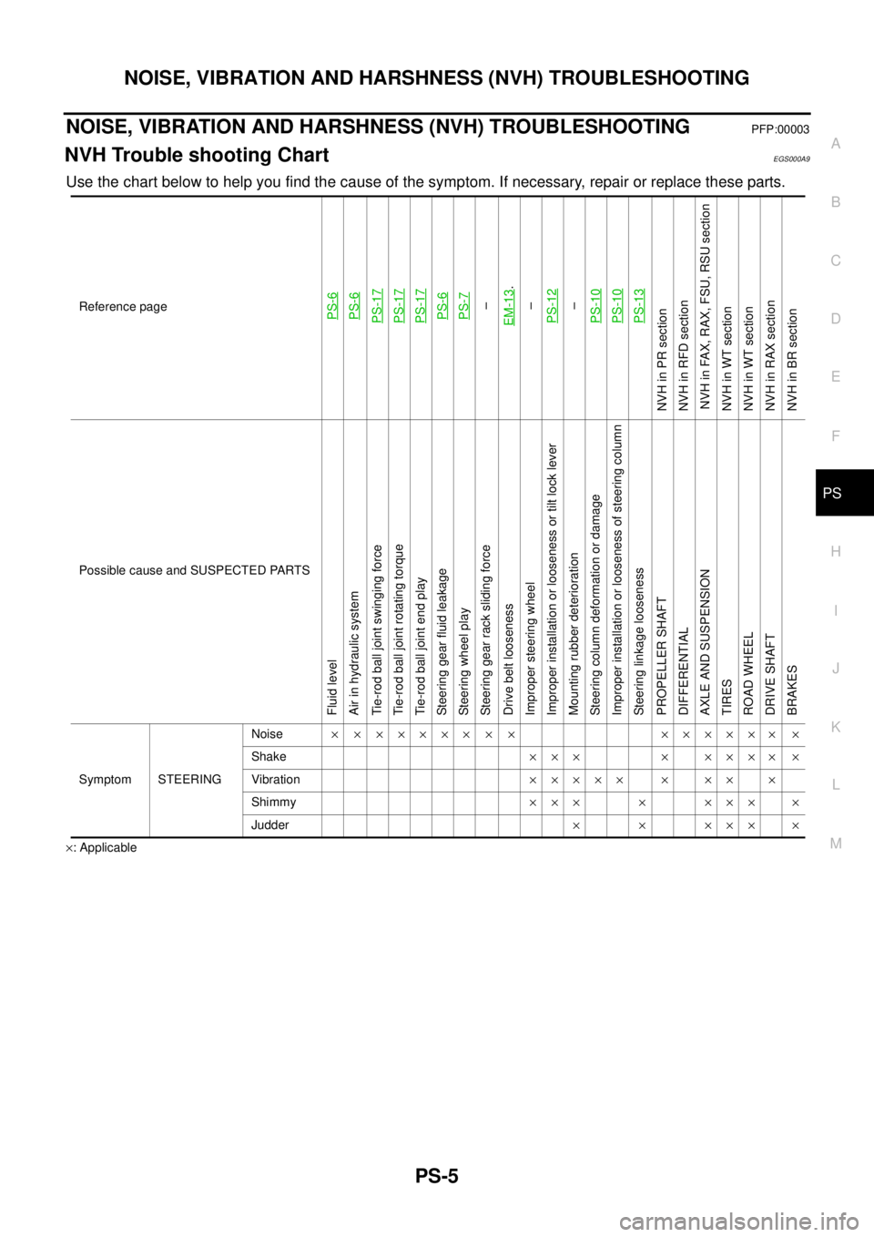
NOISE, VIBRATION AND HARSHNESS (NVH) TROUBLESHOOTING
PS-5
C
D
E
F
H
I
J
K
L
MA
B
PS
NOISE, VIBRATION AND HARSHNESS (NVH) TROUBLESHOOTINGPFP:00003
NVH Trouble shooting ChartEGS000A9
Use the chart below to help you find the cause of the symptom. If necessary, repair or replace these parts.
×: ApplicableReference page
PS-6PS-6PS-17PS-17PS-17PS-6PS-7–
EM-13
.
–
PS-12
–
PS-10PS-10PS-13
NVH in PR section
NVH in RFD section
NVH in FAX, RAX, FSU, RSU section
NVH in WT section
NVH in WT section
NVH in RAX section
NVH in BR section
Possible cause and SUSPECTED PARTS
Fluid level
Air in hydraulic system
Tie-rod ball joint swinging force
Tie-rod ball joint rotating torque
Tie-rod ball joint end play
Steering gear fluid leakage
Steering wheel play
Steering gear rack sliding force
Drive belt looseness
Improper steering wheel
Improper installation or looseness or tilt lock lever
Mounting rubber deterioration
Steering column deformation or damage
Improper installation or looseness of steering column
Steering linkage looseness
PROPELLER SHAFT
DIFFERENTIAL
AXLE AND SUSPENSION
TIRES
ROAD WHEEL
DRIVE SHAFT
BRAKES
Symptom STEERINGNoise× × ××××× × × ×××××× ×
Shake××× × ×××× ×
Vibration××××× × ×× ×
Shimmy××× × ××× ×
Judder× × ××× ×
Page 2943 of 4179
STEERING WHEEL
PS-7
C
D
E
F
H
I
J
K
L
MA
B
PS
STEERING WHEELPFP:48430
On-Vehicle Inspection and ServiceEGS0004E
PLAY INSPECTION
1. Turn steering wheel to straight-ahead position. Start engine and lightly turn steering wheel clockwise and
counter clockwise until front wheels start moving. Measure travel to starting point on circumference of
steering wheel.
2. If play is outside specifications, check following parts for proper installation: steering gear assembly, front
suspension, axles, and steering column.
�Check steering wheel for vertical, horizontal, or axial play.
�Lift vehicle and check steering gear mounting bolts and nuts for looseness.
NEUTRAL POSITION INSPECTION
�After the wheel alignment inspection, carry out the neutral position inspection. Refer to FSU-6, "Wheel
Alignment" .
�Before removing steering wheel, check steering gear neutral position.
1. Set vehicle to straight-ahead position, and check that steering wheel is in neutral position.
2. If it is not in neutral position, remove steering wheel, and install again in properly.
3. If it is not adjusted within two teeth from center of gear, loosen tie rod lock nut. Then turn it to opposite
direction to adjust until amount of left and right becomes equal.
STEERING TORQUE CHECK
1. Stop vehicle on a dry flat paved road and apply parking brake.
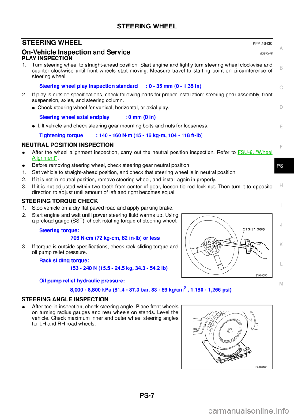
2. Start engine and wait until power steering fluid warms up. Using
a preload gauge (SST), check rotating torque of steering wheel.
3. If torque is outside specifications, check rack sliding torque and
oil pump relief pressure.
STEERING ANGLE INSPECTION
�After toe-in inspection, check steering angle. Place front wheels
on turning radius gauges and rear wheels on stands. Level the
vehicle. Check maximum inner and outer wheel steering angles
for LH and RH road wheels.Steering wheel play inspection standard : 0 - 35 mm (0 - 1.38 in)
Steering wheel axial endplay : 0 mm (0 in)
Tightening torque : 140 - 160 N·m (15 - 16 kg-m, 104 - 118 ft-lb)
Steering torque:
706 N·cm (72 kg-cm, 62 in-lb) or less
Rack sliding torque:
153 - 240 N (15.5 - 24.5 kg, 34.3 - 54.2 lb)
Oil pump relief hydraulic pressure:
8,000 - 8,800 kPa (81.4 - 87.3 bar, 83 - 89 kg/cm
2 , 1,180 - 1,266 psi)
STA0005D
FAA0016D
Page 2946 of 4179
PS-10
STEERING COLUMN
STEERING COLUMNPFP:48810
Removal and InstallationEGS00094
CAUTION:
Care must be taken not to give axial impact to steering column assembly during removal and installa-
tion.
REMOVAL OF LOWER JOINT AND HOLE COVER
1. Raise vehicle with front wheels in straight-ahead position.
2. Mark lower joint and steering gear with paint for easy installation. Remove pinch bolt from lower side of
lower joint.
3. Remove mounting bolt and nut from upper side of lower joint.
4. Remove footrest.
5. Remove hole cover and lower joint from vehicle.
6. Remove clamp and lower seal cover from hole cover.
INSTALLATION OF LOWER JOINT AND HOLE COVER
�Refer to component diagram for tightening torque. Install in the reverse order of removal.
1. Steering column assembly 2. Hole cover 3. Lower joint
4. Steering wheel 5. Air bag module 6. Spiral cable
7. Column cover
SGIA0015E
Page 2948 of 4179
PS-12
STEERING COLUMN
Disassembly and AssemblyEGS00095
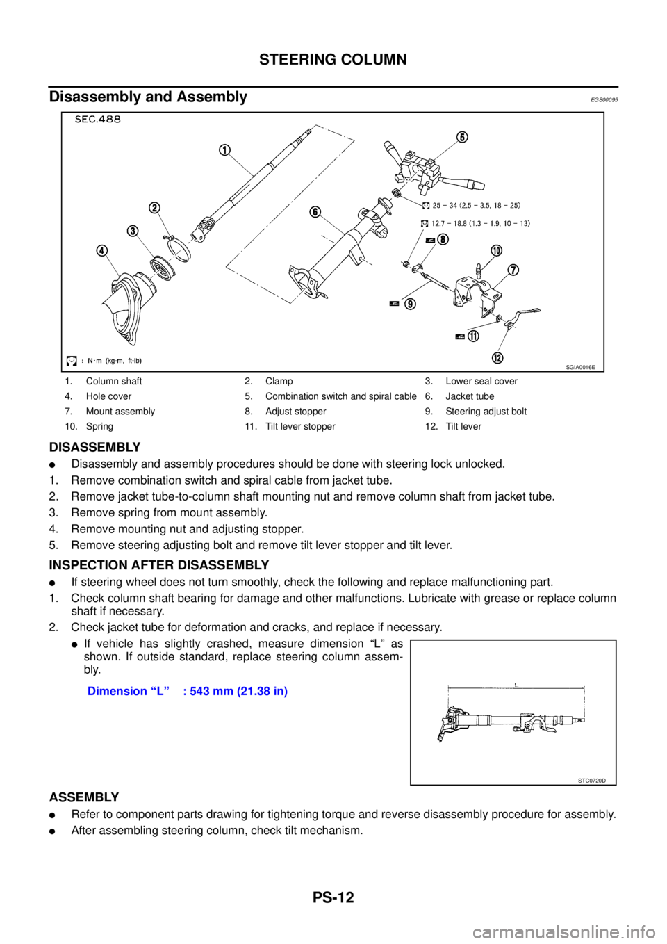
DISASSEMBLY
�Disassembly and assembly procedures should be done with steering lock unlocked.
1. Remove combination switch and spiral cable from jacket tube.
2. Remove jacket tube-to-column shaft mounting nut and remove column shaft from jacket tube.
3. Remove spring from mount assembly.
4. Remove mounting nut and adjusting stopper.
5. Remove steering adjusting bolt and remove tilt lever stopper and tilt lever.
INSPECTION AFTER DISASSEMBLY
�If steering wheel does not turn smoothly, check the following and replace malfunctioning part.
1. Check column shaft bearing for damage and other malfunctions. Lubricate with grease or replace column
shaft if necessary.
2. Check jacket tube for deformation and cracks, and replace if necessary.
�If vehicle has slightly crashed, measure dimension “L” as
shown. If outside standard, replace steering column assem-
bly.
ASSEMBLY
�Refer to component parts drawing for tightening torque and reverse disassembly procedure for assembly.
�After assembling steering column, check tilt mechanism.
1. Column shaft 2. Clamp 3. Lower seal cover
4. Hole cover 5. Combination switch and spiral cable 6. Jacket tube
7. Mount assembly 8. Adjust stopper 9. Steering adjust bolt
10. Spring 11. Tilt lever stopper 12. Tilt lever
SGIA0016E
Dimension “L” : 543 mm (21.38 in)
STC0720D
Page 2978 of 4179
PS-42
SERVICE DATA AND SPECIFICATIONS (SDS)
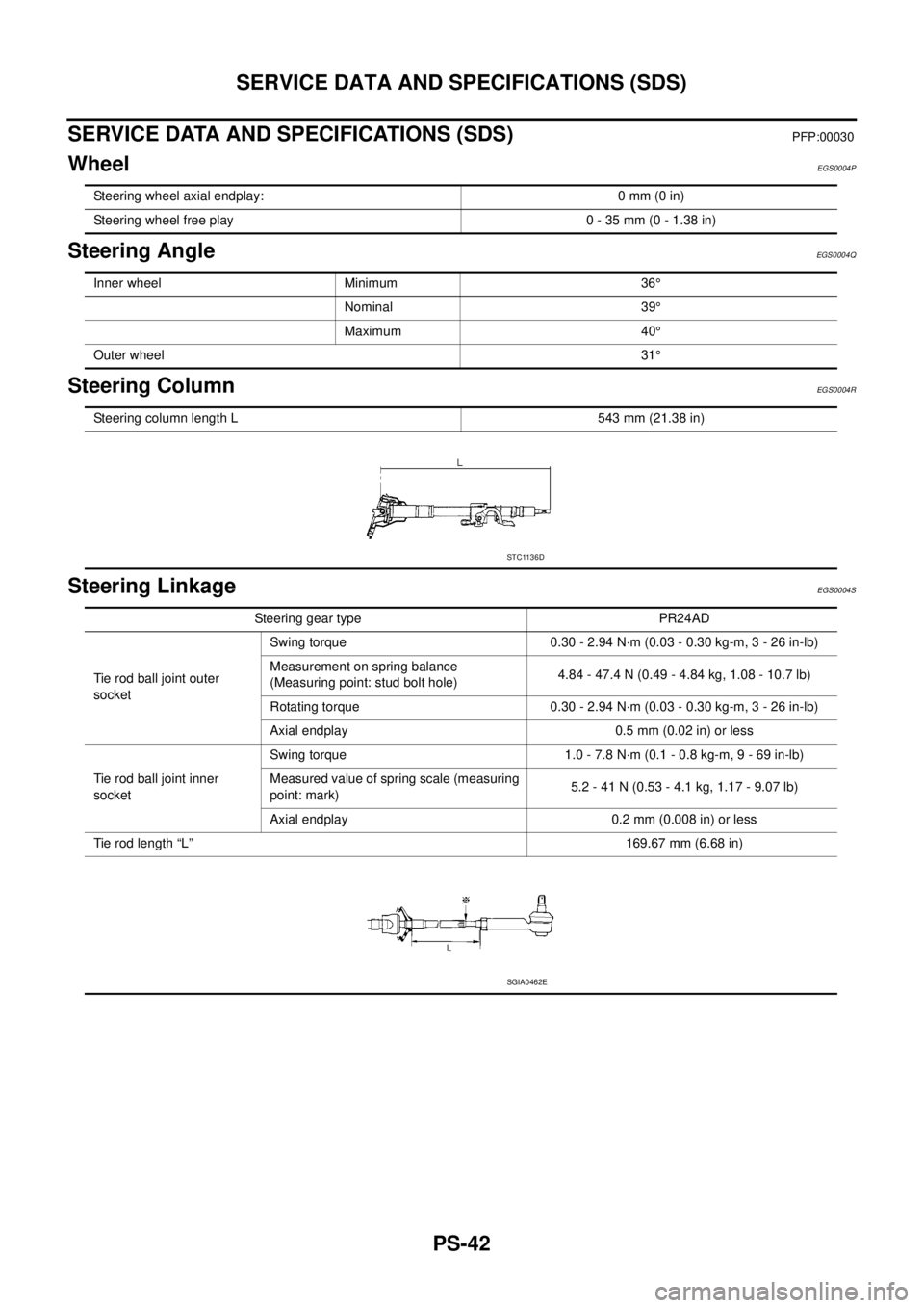
SERVICE DATA AND SPECIFICATIONS (SDS)PFP:00030
WheelEGS0004P
Steering AngleEGS0004Q
Steering ColumnEGS0004R
Steering LinkageEGS0004S
Steering wheel axial endplay: 0 mm (0 in)
Steering wheel free play 0 - 35 mm (0 - 1.38 in)
Inner wheel Minimum 36°
Nominal 39°
Maximum 40°
Outer wheel31°
Steering column length L 543 mm (21.38 in)
STC1136D
Steering gear type PR24AD
Tie rod ball joint outer
socketSwing torque 0.30 - 2.94 N·m (0.03 - 0.30 kg-m, 3 - 26 in-lb)
Measurement on spring balance
(Measuring point: stud bolt hole)4.84 - 47.4 N (0.49 - 4.84 kg, 1.08 - 10.7 lb)
Rotating torque 0.30 - 2.94 N·m (0.03 - 0.30 kg-m, 3 - 26 in-lb)
Axial endplay 0.5 mm (0.02 in) or less
Tie rod ball joint inner
socketSwing torque 1.0 - 7.8 N·m (0.1 - 0.8 kg-m, 9 - 69 in-lb)
Measured value of spring scale (measuring
point: mark)5.2 - 41 N (0.53 - 4.1 kg, 1.17 - 9.07 lb)
Axial endplay 0.2 mm (0.008 in) or less
Tie rod length “L”169.67 mm (6.68 in)
SGIA0462E
Page 3564 of 4179
MA-4
DESCRIPTION
DESCRIPTIONPFP:00000
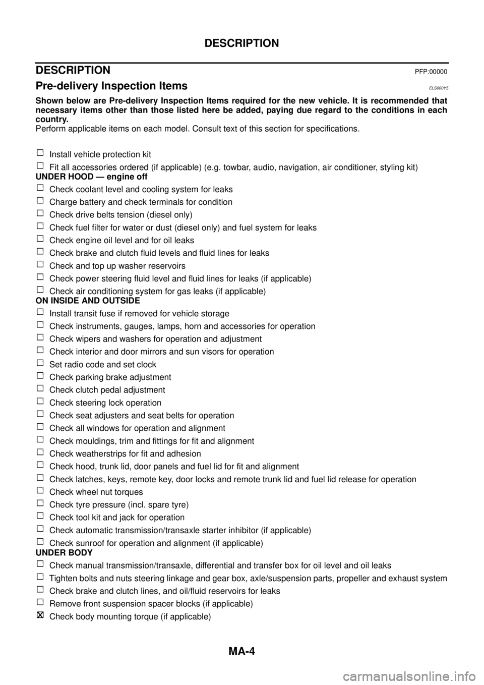
Pre-delivery Inspection ItemsELS000Y5
Shown below are Pre-delivery Inspection Items required for the new vehicle. It is recommended that
necessary items other than those listed here be added, paying due regard to the conditions in each
country.
Perform applicable items on each model. Consult text of this section for specifications.
Install vehicle protection kit
Fit all accessories ordered (if applicable) (e.g. towbar, audio, navigation, air conditioner, styling kit)
UNDER HOOD — engine off
Check coolant level and cooling system for leaks
Charge battery and check terminals for condition
Check drive belts tension (diesel only)
Check fuel filter for water or dust (diesel only) and fuel system for leaks
Check engine oil level and for oil leaks
Check brake and clutch fluid levels and fluid lines for leaks
Check and top up washer reservoirs
Check power steering fluid level and fluid lines for leaks (if applicable)
Check air conditioning system for gas leaks (if applicable)
ON INSIDE AND OUTSIDE
Install transit fuse if removed for vehicle storage
Check instruments, gauges, lamps, horn and accessories for operation
Check wipers and washers for operation and adjustment
Check interior and door mirrors and sun visors for operation
Set radio code and set clock
Check parking brake adjustment
Check clutch pedal adjustment
Check steering lock operation
Check seat adjusters and seat belts for operation
Check all windows for operation and alignment
Check mouldings, trim and fittings for fit and alignment
Check weatherstrips for fit and adhesion
Check hood, trunk lid, door panels and fuel lid for fit and alignment
Check latches, keys, remote key, door locks and remote trunk lid and fuel lid release for operation
Check wheel nut torques
Check tyre pressure (incl. spare tyre)
Check tool kit and jack for operation
Check automatic transmission/transaxle starter inhibitor (if applicable)
Check sunroof for operation and alignment (if applicable)
UNDER BODY
Check manual transmission/transaxle, differential and transfer box for oil level and oil leaks
Tighten bolts and nuts steering linkage and gear box, axle/suspension parts, propeller and exhaust system
Check brake and clutch lines, and oil/fluid reservoirs for leaks
Remove front suspension spacer blocks (if applicable)
Check body mounting torque (if applicable)
Page 3601 of 4179
CHASSIS AND BODY MAINTENANCE
MA-41
C
D
E
F
G
H
I
J
K
MA
B
MA
CAUTION:
Gaskets are not reusable. Never reuse them.
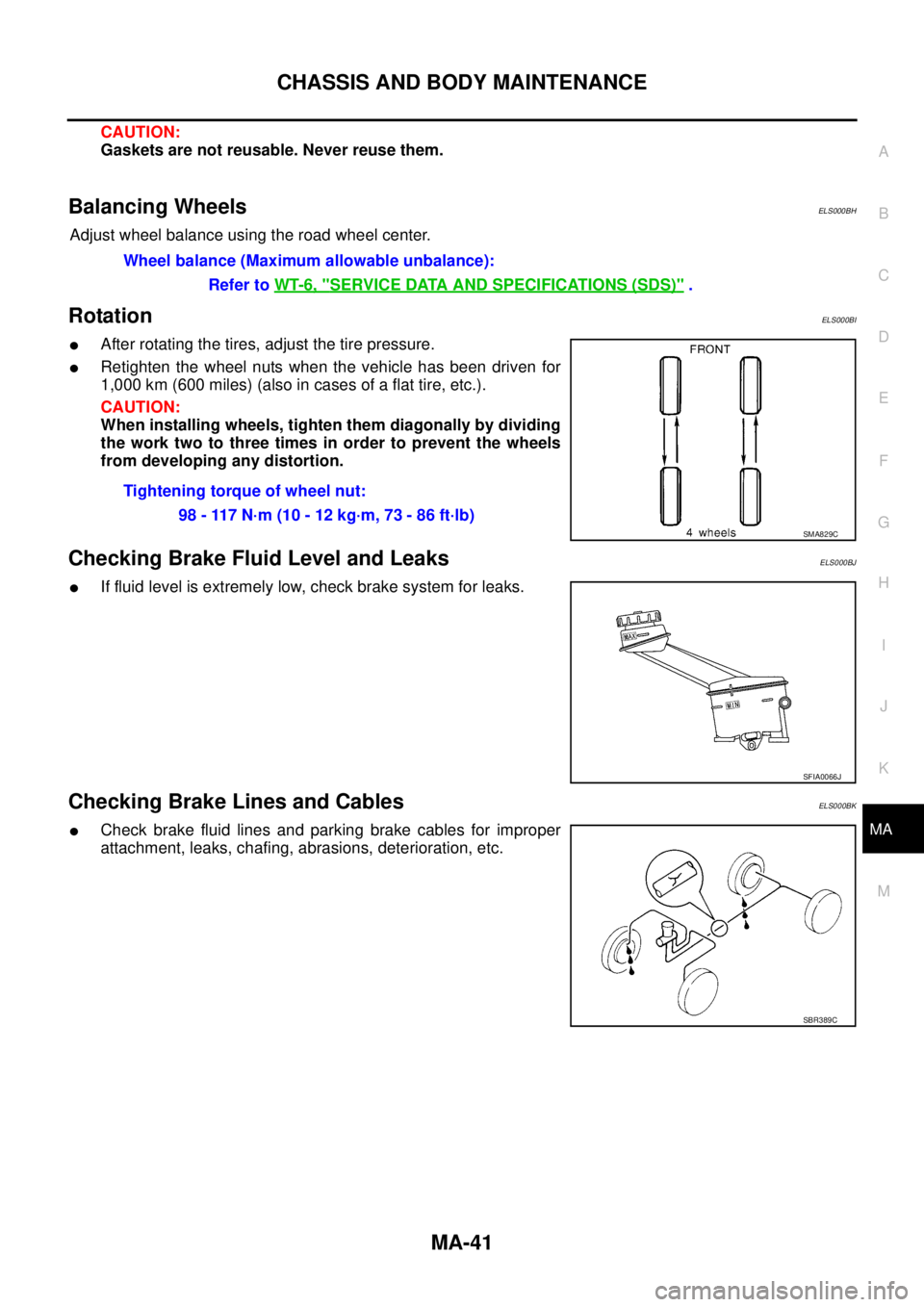
Balancing WheelsELS000BH
Adjust wheel balance using the road wheel center.
RotationELS000BI
�After rotating the tires, adjust the tire pressure.
�Retighten the wheel nuts when the vehicle has been driven for
1,000 km (600 miles) (also in cases of a flat tire, etc.).
CAUTION:
When installing wheels, tighten them diagonally by dividing
the work two to three times in order to prevent the wheels
from developing any distortion.
Checking Brake Fluid Level and LeaksELS000BJ
�If fluid level is extremely low, check brake system for leaks.
Checking Brake Lines and CablesELS000BK
�Check brake fluid lines and parking brake cables for improper
attachment, leaks, chafing, abrasions, deterioration, etc.Wheel balance (Maximum allowable unbalance):
Refer to WT-6, "
SERVICE DATA AND SPECIFICATIONS (SDS)" .
Tightening torque of wheel nut:
98 - 117 N·m (10 - 12 kg·m, 73 - 86 ft·lb)
SMA829C
SFIA0066J
SBR389C