Page 2702 of 4179
FAX-8
FRONT WHEEL HUB AND KNUCKLE
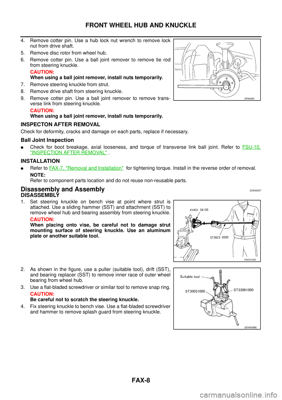
4. Remove cotter pin. Use a hub lock nut wrench to remove lock
nut from drive shaft.
5. Remove disc rotor from wheel hub.
6. Remove cotter pin. Use a ball joint remover to remove tie rod
from steering knuckle.
CAUTION:
When using a ball joint remover, install nuts temporarily.
7. Remove steering knuckle from strut.
8. Remove drive shaft from steering knuckle.
9. Remove cotter pin. Use a ball joint remover to remove trans-
verse link from steering knuckle.
CAUTION:
When using a ball joint remover, install nuts temporarily.
INSPECTON AFTER REMOVAL
Check for deformity, cracks and damage on each parts, replace if necessary.
Ball Joint Inspection
�Check for boot breakage, axial looseness, and torque of transverse link ball joint. Refer to FSU-10,
"INSPECTION AFTER REMOVAL" .
INSTALLATION
�Refer to FAX-7, "Removal and Installation" for tightening torque. Install in the reverse order of removal.
NOTE:
Refer to component parts location and do not reuse non-reusable parts.
Disassembly and AssemblyEDS0005T
DISASSEMBLY
1. Set steering knuckle on bench vise at point where strut is
attached. Use a sliding hammer (SST) and attachment (SST) to
remove wheel hub and bearing assembly from steering knuckle.
CAUTION:
When placing onto vise, be careful not to damage strut
mounting surface of steering knuckle. Use an aluminum
plate or another suitable tool.
2. As shown in the figure, use a puller (suitable tool), drift (SST),
and bearing replacer (SST) to remove inner race of outer wheel
bearing from wheel hub.
3. Use a flat-bladed screwdriver or similar tool to remove snap ring.
CAUTION:
Be careful not to scratch the steering knuckle.
4. Fix steering knuckle to bench vise. Use a flat-bladed screwdriver
and hammer to remove splash guard from steering knuckle.
SFA649A
FAC0104D
SDIA0588E
Page 2704 of 4179
FAX-10
FRONT WHEEL HUB AND KNUCKLE
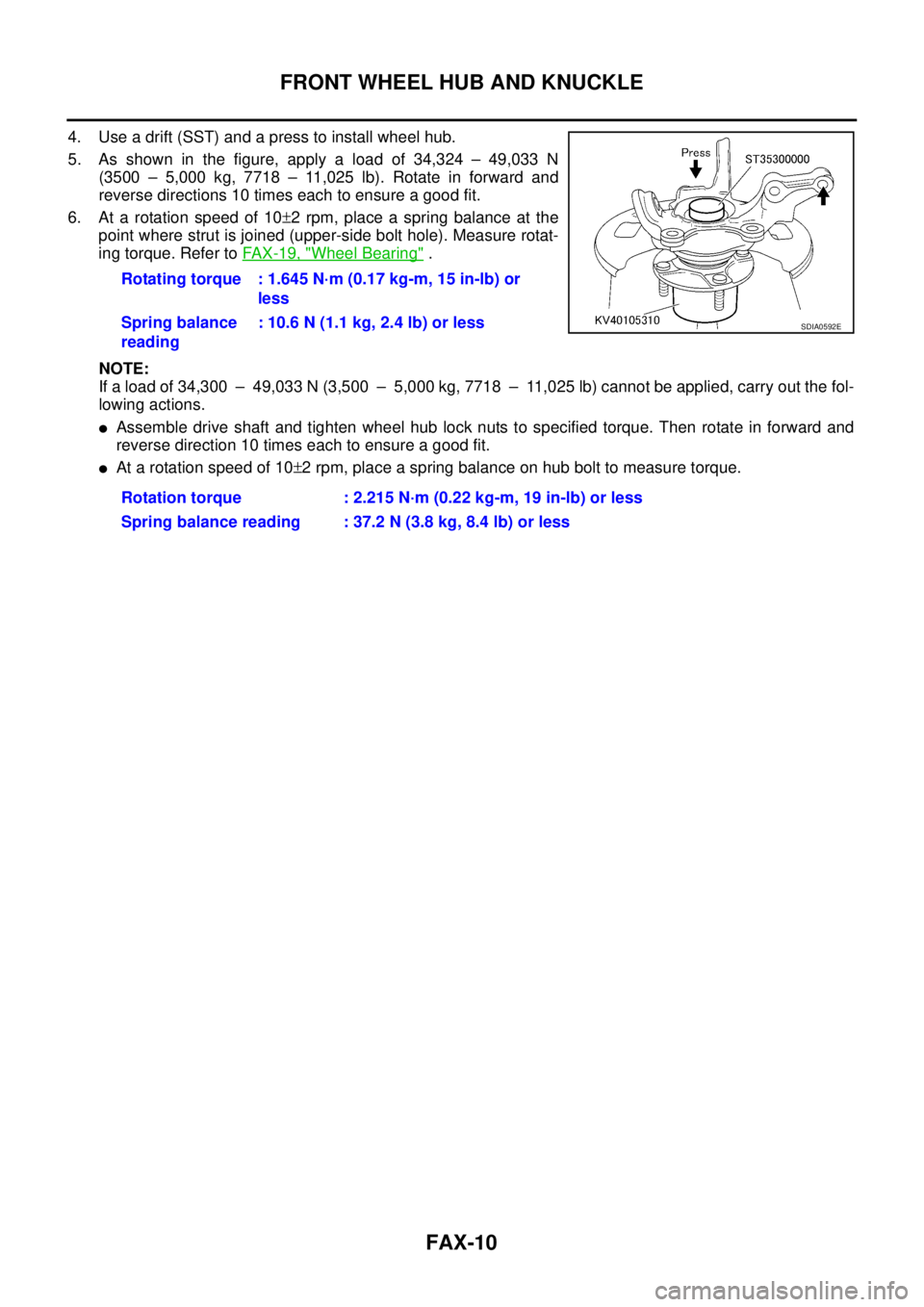
4. Use a drift (SST) and a press to install wheel hub.
5. As shown in the figure, apply a load of 34,324 – 49,033 N
(3500 – 5,000 kg, 7718 – 11,025 lb). Rotate in forward and
reverse directions 10 times each to ensure a good fit.
6. At a rotation speed of 10±2 rpm, place a spring balance at the
point where strut is joined (upper-side bolt hole). Measure rotat-
ing torque. Refer to FA X - 1 9 , "
Wheel Bearing" .
NOTE:
If a load of 34,300 – 49,033 N (3,500 – 5,000 kg, 7718 – 11,025 lb) cannot be applied, carry out the fol-
lowing actions.
�Assemble drive shaft and tighten wheel hub lock nuts to specified torque. Then rotate in forward and
reverse direction 10 times each to ensure a good fit.
�At a rotation speed of 10±2 rpm, place a spring balance on hub bolt to measure torque. Rotating torque : 1.645 N·m (0.17 kg-m, 15 in-lb) or
less
Spring balance
reading: 10.6 N (1.1 kg, 2.4 lb) or less
Rotation torque : 2.215 N·m (0.22 kg-m, 19 in-lb) or less
Spring balance reading : 37.2 N (3.8 kg, 8.4 lb) or less
SDIA0592E
Page 2706 of 4179
FAX-12
FRONT DRIVE SHAFT
×: Applicable
–: Not applicable
�Remove installation bolts from right-side drive shaft support bearing bracket. Then remove bracket from
engine.
�Remove installation bolts from right-side drive shaft and remove drive shaft from side shaft.
INSPECTION AFTER REMOVAL
�Move joint in up/down, left/right, and axial directions. Check for
motion that is not smooth and for significant looseness.
�Check for cracking and damage of boots, and for grease leak-
age.
INSTALLATION
�Install support bearing bracket onto engine and tighten installation bolts to specified torque. Refer to FA X -
11 , "Removal and Installation" .
�Install drive shaft to side shaft and tighten installation bolts to specified torque. Refer to FA X - 11 , "Removal
and Installation" .
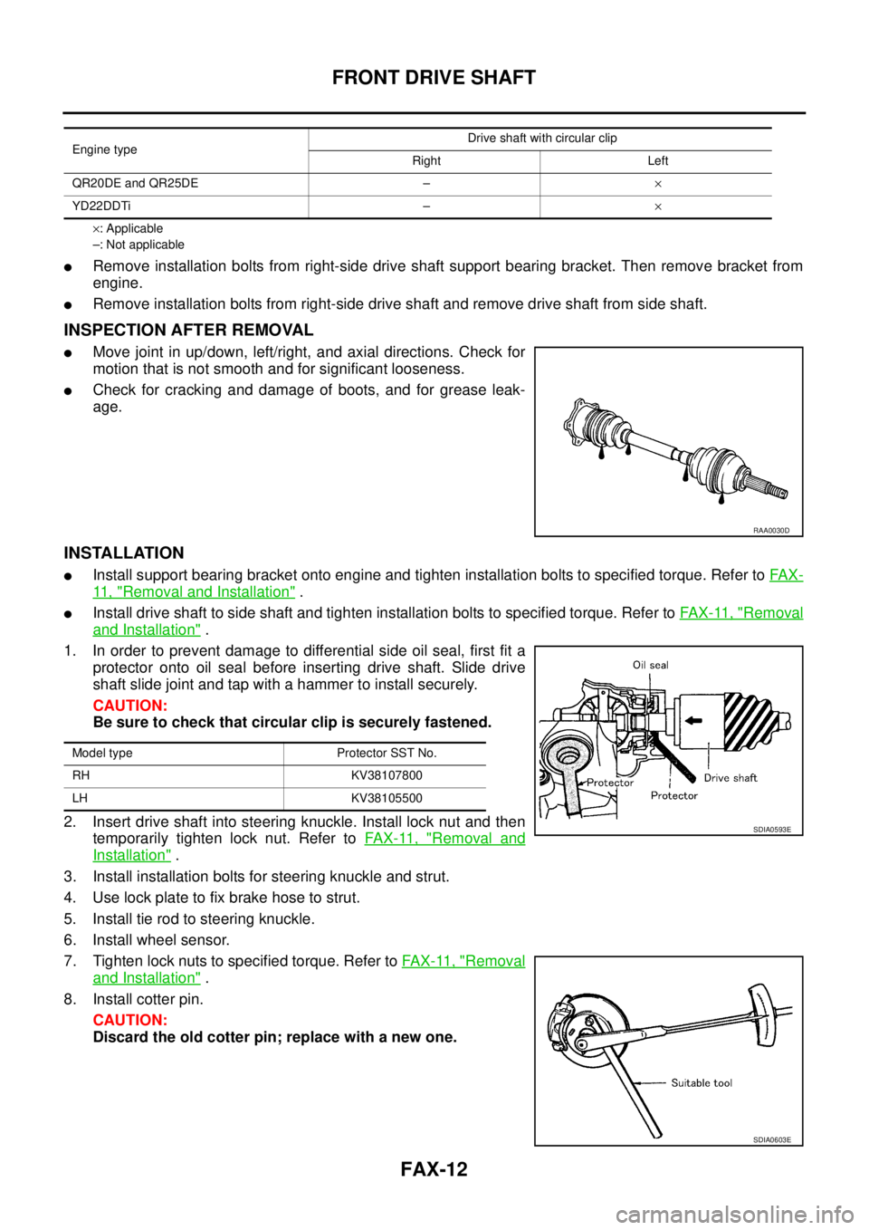
1. In order to prevent damage to differential side oil seal, first fit a
protector onto oil seal before inserting drive shaft. Slide drive
shaft slide joint and tap with a hammer to install securely.
CAUTION:
Be sure to check that circular clip is securely fastened.
2. Insert drive shaft into steering knuckle. Install lock nut and then
temporarily tighten lock nut. Refer to FA X - 11 , "
Removal and
Installation" .
3. Install installation bolts for steering knuckle and strut.
4. Use lock plate to fix brake hose to strut.
5. Install tie rod to steering knuckle.
6. Install wheel sensor.
7. Tighten lock nuts to specified torque. Refer to FAX-11, "
Removal
and Installation" .
8. Install cotter pin.
CAUTION:
Discard the old cotter pin; replace with a new one.
Engine typeDrive shaft with circular clip
Right Left
QR20DE and QR25DE –×
YD22DDTi –×
RAA0030D
Model type Protector SST No.
RH KV38107800
LH KV38105500
SDIA0593E
SDIA0603E
Page 2713 of 4179
SERVICE DATA AND SPECIFICATIONS (SDS)
FAX-19
C
E
F
G
H
I
J
K
L
MA
B
FA X
SERVICE DATA AND SPECIFICATIONS (SDS)PFP:00030
Wheel BearingEDS000IG
Drive ShaftEDS000IH
ZF100SS86, ZF100SS86F, ZF100SS86F+B
Dynamic DamperEDS000II
Axial end play 0.05 mm (0.0020 in)
Rotating torque 1.645 N·m (0.17 kg-m, 15 in-lb) or less
Spring balance reading 10.6 N (1.1 kg, 2.4 lb) or less
Installation location of spring scale
SDIA0148E
Joint type Wheel side Transaxle side
Grease amount 115 - 125 g (4.01 - 4.41 oz) 132 - 142 g (4.69 - 5.04 oz)
Boot length 100 - 103 mm (3.94 - 4.06 in) 84 - 86 mm (3.31 - 3.39 in)
Drive shaft model Applied model Specification Dimension A Dimension B
ZF100SS86 ALL Left 205 - 215 mm (8.07 - 8.46 in) 70 mm (2.76 in)
ZF100SS86F+ BRHD: QR25DE A/T models
QR25DE: M/T models
Right 267 - 273 mm (10.51 - 10.75 in)70 mm (2.76 in)
QR20DE/YD22DDTi M/T models 50 mm (1.97 in)
FAC0156D
Page 2721 of 4179
WHEEL HUB (4WD)
RAX-7
C
E
F
G
H
I
J
K
L
MA
B
RAX
REMOVAL
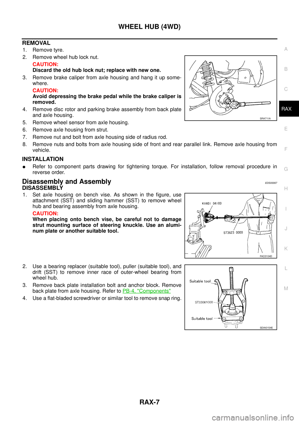
1. Remove tyre.
2. Remove wheel hub lock nut.
CAUTION:
Discard the old hub lock nut; replace with new one.
3. Remove brake caliper from axle housing and hang it up some-
where.
CAUTION:
Avoid depressing the brake pedal while the brake caliper is
removed.
4. Remove disc rotor and parking brake assembly from back plate
and axle housing.
5. Remove wheel sensor from axle housing.
6. Remove axle housing from strut.
7. Remove nut and bolt from axle housing side of radius rod.
8. Remove nuts and bolts from axle housing side of front and rear parallel link. Remove axle housing from
vehicle.
INSTALLATION
�Refer to component parts drawing for tightening torque. For installation, follow removal procedure in
reverse order.
Disassembly and AssemblyEDS00067
DISASSEMBLY
1. Set axle housing on bench vise. As shown in the figure, use
attachment (SST) and sliding hammer (SST) to remove wheel
hub and bearing assembly from axle housing.
CAUTION:
When placing onto bench vise, be careful not to damage
strut mounting surface of steering knuckle. Use an alumi-
num plate or another suitable tool.
2. Use a bearing replacer (suitable tool), puller (suitable tool), and
drift (SST) to remove inner race of outer-wheel bearing from
wheel hub.
3. Remove back plate installation bolt and anchor block. Remove
back plate from axle housing. Refer to PB-4, "
Components"
4. Use a flat-bladed screwdriver or similar tool to remove snap ring.
SRA711A
FAC0104D
SDIA0154E
Page 2722 of 4179
RAX-8
WHEEL HUB (4WD)
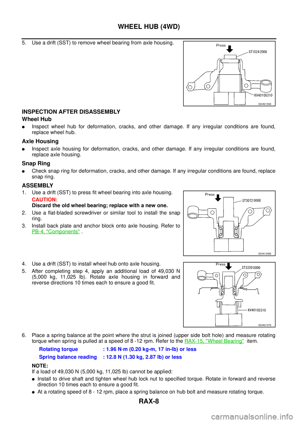
5. Use a drift (SST) to remove wheel bearing from axle housing.
INSPECTION AFTER DISASSEMBLY
Wheel Hub
�Inspect wheel hub for deformation, cracks, and other damage. If any irregular conditions are found,
replace wheel hub.
Axle Housing
�Inspect axle housing for deformation, cracks, and other damage. If any irregular conditions are found,
replace axle housing.
Snap Ring
�Check snap ring for deformation, cracks, and other damage. If any irregular conditions are found, replace
snap ring.
ASSEMBLY
1. Use a drift (SST) to press fit wheel bearing into axle housing.
CAUTION:
Discard the old wheel bearing; replace with a new one.
2. Use a flat-bladed screwdriver or similar tool to install the snap
ring.
3. Install back plate and anchor block onto axle housing. Refer to
PB-4, "
Components" .
4. Use a drift (SST) to install wheel hub onto axle housing.
5. After completing step 4, apply an additional load of 49,030 N
(5,000 kg, 11,025 lb). Rotate axle housing in forward and
reverse directions 10 times each to ensure a good fit.
6. Place a spring balance at the point where the strut is joined (upper side bolt hole) and measure rotating
torque when spring is pulled at a speed of 8 -12 rpm. Refer to the RAX-15, "
Wheel Bearing" item.
NOTE:
If a load of 49,030 N (5,000 kg, 11,025 lb) cannot be applied:
�Install to drive shaft and tighten wheel hub lock nut to specified torque. Rotate in forward and reverse
direction 10 times each to ensure a good fit.
�At a rotating speed of 8 - 12 rpm, place a spring balance on hub bolt and measure rotating torque.
SDIA0155E
SDIA1349E
SDIA0157E
Rotating torque : 1.96 N·m (0.20 kg-m, 17 in-lb) or less
Spring balance reading : 12.8 N (1.30 kg, 2.87 lb) or less
Page 2723 of 4179
WHEEL HUB (4WD)
RAX-9
C
E
F
G
H
I
J
K
L
MA
B
RAX
Rotating torque : 1.126 N·m (0.11 kg-m, 10 in-lb)
Spring balance reading : 19.70 N (2.01 kg, 4.43 lb)
Page 2729 of 4179
SERVICE DATA AND SPECIFICATIONS (SDS)
RAX-15
C
E
F
G
H
I
J
K
L
MA
B
RAX
SERVICE DATA AND SPECIFICATIONS (SDS)PFP:00030
Wheel BearingEDS000ID
Drive ShaftEDS000IE
Rotation torque 1.96 N·m (0.20 kg-m, 17 in-lb) or less
Spring balance reading 12.8 N (1.30 kg) or less
Installation location of spring balance mm (in)
Axial end play 0.05 mm (0.0020 in) or less
SDIA0148E
Specified amount of greaseFinal drive side 40 - 50 g (1.41 - 1.77 oz)
Wheel side 35 - 45 g (1.23 - 1.59 oz)
Boot lengthFinal drive side (L
2 ) 78.6 - 80.6 mm (3.094 - 3.173 in)
Wheel side (L
1 ) 66.7 - 68.7 mm (2.626 - 2.705 in)
SDIA0618E