Page 3688 of 4179
DI-10
COMBINATION METERS
TYPE 5
System diagram
Input/output signal chart
T: Transmit R: Receive
PKIA6460E
Signals ECM TCMESP/TCS/
ABS control
unitSte ering
angle sensor4WD control
unitCombination
meter
Stop lamp switch signalRT
TR
P·N range signal R T
A/T position indicator lamp signal T R R
O/D OFF indicator signal T R
Overdrive control switch signal R T
Engine speed signal T R R R
Engine coolant temperature signal TR
A/C compressor feedback signal TR
Vehicle speed signalTRR
RT
ABS warning lamp signal T R
Brake warning lamp signal T R
SLIP indicator lamp signal T R
ESP OFF indicator lamp signal T R
4WD warning lamp signalTR
4WD mode indicator lamp signalTR
Parking brake switch signalRT
MI signal TR
Page 3782 of 4179
![NISSAN X-TRAIL 2003 Service Repair Manual LAN-4
[CAN]
CAN COMMUNICATION
CAN COMMUNICATIONPFP:23710
System DescriptionEKS001U3
CAN (Controller Area Network) is a serial communication line for real time application. It is an on-vehicle mul-
t NISSAN X-TRAIL 2003 Service Repair Manual LAN-4
[CAN]
CAN COMMUNICATION
CAN COMMUNICATIONPFP:23710
System DescriptionEKS001U3
CAN (Controller Area Network) is a serial communication line for real time application. It is an on-vehicle mul-
t](/manual-img/5/57404/w960_57404-3781.png)
LAN-4
[CAN]
CAN COMMUNICATION
CAN COMMUNICATIONPFP:23710
System DescriptionEKS001U3
CAN (Controller Area Network) is a serial communication line for real time application. It is an on-vehicle mul-
tiplex communication line with high data communication speed and excellent error detection ability. Many elec-
tronic control units are equipped onto a vehicle, and each control unit shares information and links with other
control units during operation (not independent). In CAN communication, control units are connected with 2
communication lines (CAN H line, CAN L line) allowing a high rate of information transmission with less wiring.
Each control unit transmits/receives data but selectively reads required data only.
CAN Communication UnitEKS00EGL
Go to CAN system, when selecting your CAN system type from the following table.
TYPE 1
System diagram
Input/output signal chart
T: Transmit R: Receive Body typeWagon
Axle4WD
Engine QR20DE/QR25DE QR25DE YD22DDTi QR25DE
Transmission M/T A/T M/T A/T
Brake control ABS ESP
CAN system type 1 2 3 4 5
CAN system trouble diagnosisLAN-9
LAN-25LAN-50LAN-68LAN-86
PKIA6458E
Signals ECMABS actuator and
electric unit
(control unit)4WD control unit Combination meter
Stop lamp switch signal T R
Engine speed signal T R R
Engine coolant temperature signal T R
Accelerator pedal position signal T R
A/C compressor feedback signal T R
Vehicle speed signalTRR
RT
Page 3783 of 4179
CAN COMMUNICATION
LAN-5
[CAN]
C
D
E
F
G
H
I
J
L
MA
B
LAN
TYPE 2
System diagram
Input/output signal chart
T: Transmit R: Receive ABS warning lamp signal T R
4WD warning lamp signalTR
4WD mode indicator lamp signal T R
Parking brake switch signalRT
MI signal T RSignals ECMABS actuator and
electric unit
(control unit)4WD control unit Combination meter
PKIA6457E
Signals ECM TCMABS actuator
and electric unit
(control unit)4WD control
unitCombination
meter
Stop lamp switch signalRT
TR
P·N range signal R T
A/T position indicator lamp signal T R
Overdrive control switch signal R T
O/D OFF indicator signal T R
Closed throttle position signal T R
Wide open throttle position signal T R
Engine speed signal T R R
Engine coolant temperature signal TR
Accelerator pedal position signal T R
Output shaft revolution signal R T
A/C compressor feedback signal TR
Vehicle speed signalTRR
RT
ABS warning lamp signal T R
Page 3784 of 4179
LAN-6
[CAN]
CAN COMMUNICATION
TYPE 3/TYPE4
System diagram
Input/output signal chart
T: Transmit R: Receive 4WD warning lamp signalTR
4WD mode indicator lamp signalTR
Parking brake switch signalRT
MI signal TR
Engine A/T integrated control signalTR
RT
A/T self-diagnosis signal R TSignals ECM TCMABS actuator
and electric unit
(control unit)4WD control
unitCombination
meter
PKIA9634E
Signals ECMESP/TCS/ABS
control unitSteering angle
sensor4WD control
unitCombination
meter
Stop lamp switch signal T R
Engine speed signal T R R R
Engine coolant temperature signal TR
Accelerator pedal position signal T R R
A/C switch signal*
1RT
A/C compressor feedback signal*
2TR
Vehicle speed signalTRR
RT
ABS warning lamp signal T R
Brake warning lamp signal T R
SLIP indicator lamp signal T R
ESP OFF indicator lamp signal T R
4WD warning lamp signalTR
4WD mode indicator lamp signalTR
Parking brake switch signalRT
Page 3785 of 4179
CAN COMMUNICATION
LAN-7
[CAN]
C
D
E
F
G
H
I
J
L
MA
B
LAN
*1: YD engine models only
*2: QR engine models only
TYPE 5
System diagram
Input/output signal chart
T: Transmit R: Receive MI signal TR
Glow indicator lamp signal*
1TR
Steering angle sensor signal R TSignals ECMESP/TCS/ABS
control unitSteering angle
sensor4WD control
unitCombination
meter
PKIA9635E
Signals ECM TCMESP/TCS/
ABS control
unitSteering
angle sensor4WD control
unitCombination
meter
Stop lamp switch signalRT
TR
P·N range signal R T
A/T position indicator lamp signal T R R
O/D OFF indicator signal T R
Overdrive control switch signal R T
Closed throttle position signal T R
Wide open throttle position signal T R
Engine speed signal T R R R
Engine coolant temperature signal TR
Accelerator pedal position signal T R R
Output shaft revolution signal R T
A/C compressor feedback signal TR
Vehicle speed signalTRR
RT
ABS warning lamp signal T R
Brake warning lamp signal T R
Page 4063 of 4179

HARNESS
PG-61
C
D
E
F
G
H
I
J
L
MA
B
PG
Wiring Diagram Codes (Cell Codes) EKS0032J
Use the chart below to find out what each wiring diagram code stands for.
Refer to the wiring diagram code in the alphabetical index to find the location (page number) of each wiring
diagram.
Code Section Wiring Diagram Name
1STSIG AT A/T 1st Signal
2NDSIG AT A/T 2nd Signal
3RDSIG AT A/T 3rd Signal
4THSIG AT A/T 4th Signal
4WD TF 4WD Control system
A/C ATC Air Conditioner
ABS BRC Anti-Lock Brake System
APP1PW EC Accelerator Pedal Position Sensor 1 Power Supply
APP2PW EC Accelerator Pedal Position Sensor 2 Power Supply
APPS1 EC Accelerator Pedal Position Sensor
APPS2 EC Accelerator Pedal Position Sensor
APPS3 EC Accelerator Pedal Position Sensor
AT/IND DI A/T Indicator
AUDIO AV Audio
BA/FTS AT A/T Fluid Temperature Sensor and TCM Power Supply
BACK/L LT Back-Up Lamp
BOOST EC Turbocharger Boost Sensor
BRK/SW EC Brake Switch
CAN AT CAN Communication Line
CAN EC CAN Communication Line
CAN LAN CAN System
CHARGE SC Charging System
CHIME DI Warning Chime
CIGAR WW Cigarette Lighter
CLOCK DI Clock
CKPS EC Crankshaft Position Sensor
CMPS EC Camshaft Position Sensor
COOL/F EC Cooling Fan Control
D/LOCK BL Power Door Lock
DEF GW Rear Window Defogger
DTRL LT Headlamp - With Daytime Light System
ECM/PW EC ECM Power Supply for Back-Up
ECMRLY EC ECM Relay
ECTS EC Engine Coolant Temperature Sensor
EGVC/V EC EGR Volume Control Valve
EGRVLV EC EGR Volume Control Valve
ENGSS AT Engine Speed Signal
ESP BRC ESP/TCS/ABS Control System
ETC1 EC Electric Throttle Control Function
ETC2 EC Electric Throttle Control Motor Relay
ETC3 EC Electric Throttle Control Motor
Page 4092 of 4179

LT-14
HEADLAMP
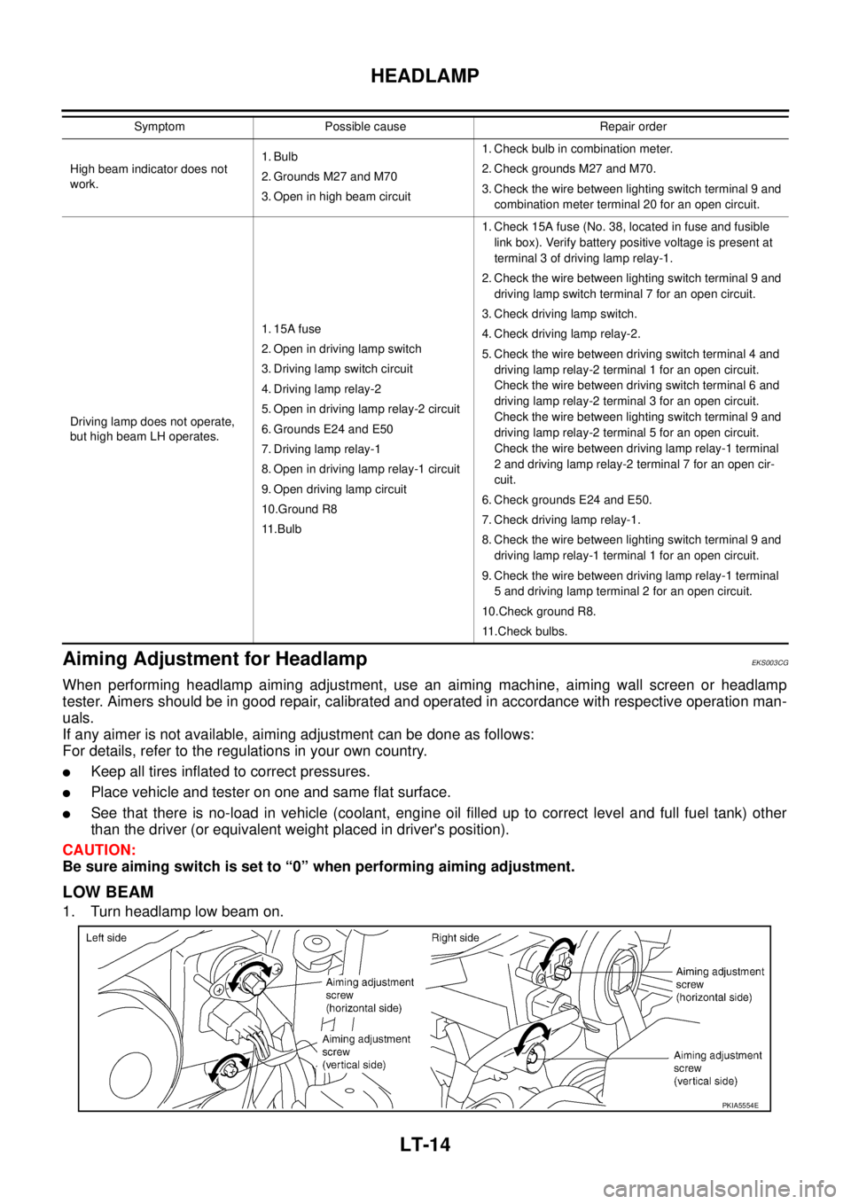
Aiming Adjustment for HeadlampEKS003CG
When performing headlamp aiming adjustment, use an aiming machine, aiming wall screen or headlamp
tester. Aimers should be in good repair, calibrated and operated in accordance with respective operation man-
uals.
If any aimer is not available, aiming adjustment can be done as follows:
For details, refer to the regulations in your own country.
�Keep all tires inflated to correct pressures.
�Place vehicle and tester on one and same flat surface.
�See that there is no-load in vehicle (coolant, engine oil filled up to correct level and full fuel tank) other
than the driver (or equivalent weight placed in driver's position).
CAUTION:
Be sure aiming switch is set to “0” when performing aiming adjustment.
LOW BEAM
1. Turn headlamp low beam on.
High beam indicator does not
work.1. Bulb
2. Grounds M27 and M70
3. Open in high beam circuit1. Check bulb in combination meter.
2. Check grounds M27 and M70.
3. Check the wire between lighting switch terminal 9 and
combination meter terminal 20 for an open circuit.
Driving lamp does not operate,
but high beam LH operates.1. 15A fuse
2. Open in driving lamp switch
3. Driving lamp switch circuit
4. Driving lamp relay-2
5. Open in driving lamp relay-2 circuit
6. Grounds E24 and E50
7. Driving lamp relay-1
8. Open in driving lamp relay-1 circuit
9. Open driving lamp circuit
10.Ground R8
11 . B u l b1. Check 15A fuse (No. 38, located in fuse and fusible
link box). Verify battery positive voltage is present at
terminal 3 of driving lamp relay-1.
2. Check the wire between lighting switch terminal 9 and
driving lamp switch terminal 7 for an open circuit.
3. Check driving lamp switch.
4. Check driving lamp relay-2.
5. Check the wire between driving switch terminal 4 and
driving lamp relay-2 terminal 1 for an open circuit.
Check the wire between driving switch terminal 6 and
driving lamp relay-2 terminal 3 for an open circuit.
Check the wire between lighting switch terminal 9 and
driving lamp relay-2 terminal 5 for an open circuit.
Check the wire between driving lamp relay-1 terminal
2 and driving lamp relay-2 terminal 7 for an open cir-
cuit.
6. Check grounds E24 and E50.
7. Check driving lamp relay-1.
8. Check the wire between lighting switch terminal 9 and
driving lamp relay-1 terminal 1 for an open circuit.
9. Check the wire between driving lamp relay-1 terminal
5 and driving lamp terminal 2 for an open circuit.
10.Check ground R8.
11.Check bulbs. Symptom Possible cause Repair order
PKIA5554E
Page 4093 of 4179

HEADLAMP
LT-15
C
D
E
F
G
H
I
J
L
MA
B
LT
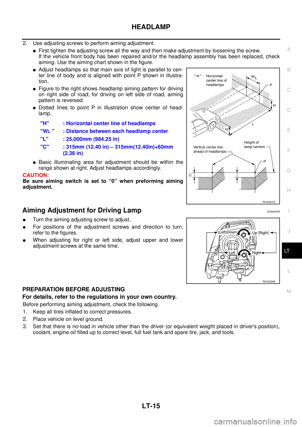
2. Use adjusting screws to perform aiming adjustment.
�First tighten the adjusting screw all the way and then make adjustment by loosening the screw.
If the vehicle front body has been repaired and/or the headlamp assembly has been replaced, check
aiming. Use the aiming chart shown in the figure.
�Adjust headlamps so that main axis of light is parallel to cen-
ter line of body and is aligned with point P shown in illustra-
tion.
�Figure to the right shows headlamp aiming pattern for driving
on right side of road; for driving on left side of road, aiming
pattern is reversed.
�Dotted lines to point P in illustration show center of head-
lamp.
�Basic illuminating area for adjustment should be within the
range shown at right. Adjust headlamps accordingly.
CAUTION:
Be sure aiming switch is set to “0” when preforming aiming
adjustment.
Aiming Adjustment for Driving LampEKS00AP6
�Turn the aiming adjusting screw to adjust.
�For positions of the adjustment screws and direction to turn,
refer to the figures.
�When adjusting for right or left side, adjust upper and lower
adjustment screws at the same time.
PREPARATION BEFORE ADJUSTING
For details, refer to the regulations in your own country.
Before performing aiming adjustment, check the following.
1. Keep all tires inflated to correct pressures.
2. Place vehicle on level ground.
3. Set that there is no-load in vehicle other than the driver (or equivalent weight placed in driver's position),
coolant, engine oil filled up to correct level, full fuel tank and spare tire, jack, and tools."H" : Horizontal center line of headlamps
"W
L " : Distance between each headlamp center
"L" : 25,000mm (984.25 in)
"C" : 315mm (12.40 in) – 315mm(12.40in)+60mm
(2.36 in)
PKIA3537E
PKIA3394E