Page 2554 of 4179
AT-518
[ALL]
ASSEMBLY
14. Install snap ring with flat-bladed screwdriver.
CAUTION:
Forward clutch and bearing must be correctly installed for
snap ring to fit into groove of transaxle case.
15. Install front sun gear according to the following procedures.
a. Install bearing race on front sun gear.
CAUTION:
Apply petroleum jelly to bearing race.
b. Install needle bearing on front sun gear.
CAUTION:
�Apply petroleum jelly to needle bearing.
�Pay attention to the direction of needle bearing.
c. Install front sun gear on front planetary carrier.
16. Install high clutch hub according to the following procedures.
a. Install needle bearing on front sun gear.
CAUTION:
�Apply petroleum jelly to needle bearing.
�Pay attention to the direction of needle bearing.
SCIA3633E
SCIA4033E
SCIA4458E
SCIA4034E
Page 2555 of 4179
ASSEMBLY
AT-519
[ALL]
D
E
F
G
H
I
J
K
L
MA
B
AT
b. Install high clutch hub on front sun gear.
17. Install input shaft assembly (high clutch assembly) according to the following procedures.
a. Install needle bearing on high clutch hub.
CAUTION:
�Apply petroleum jelly.
�Pay attention to the direction of needle bearing.
b. Install input shaft assembly (high clutch assembly) on high
clutch hub.
c. Install needle bearing on input shaft assembly (high clutch
drum).
CAUTION:
�Apply petroleum jelly to needle bearing.
�Be careful with the direction of needle bearing.
SCIA4459E
SCIA4035E
SCIA4036E
SCIA4872E
Page 2556 of 4179
AT-520
[ALL]
ASSEMBLY
18. Install reverse clutch assembly on input shaft assembly (high
clutch drum).
Adjustment (2)ECS004MG
When any parts listed below are replaced, adjust total end play and reverse clutch end play.
TOTAL END PLAY
�Measure the clearance between reverse clutch drum and needle
bearing for oil pump cover.
�Select proper thickness of bearing race so that end play is within
specifications.
1. Measure dimensions “K” and “L” and then calculate dimension
“J”.
SCIA4461E
Part name Total end play Reverse clutch end play
transaxle case��
Overrun clutch hub��
Rear internal gear��
Rear planetary carrier��
Rear sun gear��
Front planetary carrier��
Front sun gear��
High clutch hub��
High clutch drum��
Oil pump cover��
Reverse clutch drum —�
SCIA3661E
SCIA3662E
Page 2557 of 4179
ASSEMBLY
AT-521
[ALL]
D
E
F
G
H
I
J
K
L
MA
B
AT
a. Measure dimension “K”.
b. Measure dimension “L”.
c. Calculate dimension “J”.
2. Measure dimension “M”.
a. Place bearing race and needle bearing on oil pump assembly.
b. Measure dimension “M”.
c. Measure thickness of straightedge “t”.
SCIA3663E
“J”: Distance between oil pump fitting surface of
transaxle case and needle bearing mating surface of
high clutch drum.
J = K – L
SCIA3664E
SAT378D
“M”: Distance between transaxle case fitting surface of
oil pump cover and needle bearing on oil pump cover.
“M
1 ”: Indication of gauge.
SAT379D
M = M1 – t
SAT443D
Page 2558 of 4179
AT-522
[ALL]
ASSEMBLY
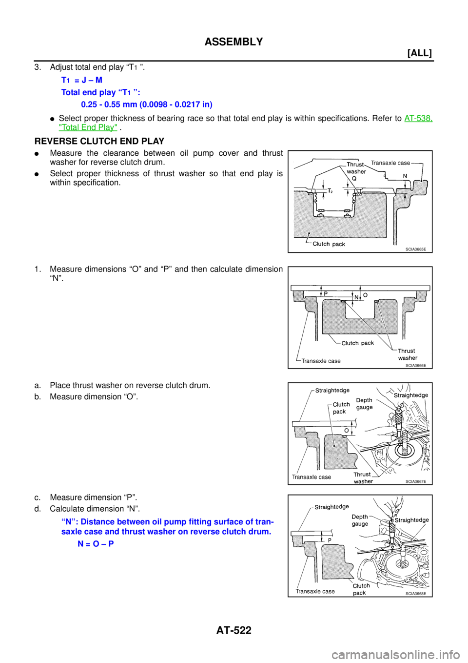
3. Adjust total end play “T1 ”.
�Select proper thickness of bearing race so that total end play is within specifications. Refer to AT- 5 3 8 ,
"Total End Play" .
REVERSE CLUTCH END PLAY
�Measure the clearance between oil pump cover and thrust
washer for reverse clutch drum.
�Select proper thickness of thrust washer so that end play is
within specification.
1. Measure dimensions “O” and “P” and then calculate dimension
“N”.
a. Place thrust washer on reverse clutch drum.
b. Measure dimension “O”.
c. Measure dimension “P”.
d. Calculate dimension “N”.T
1 = J – M
Total end play “T
1 ”:
0.25 - 0.55 mm (0.0098 - 0.0217 in)
SCIA3665E
SCIA3666E
SCIA3667E
“N”: Distance between oil pump fitting surface of tran-
saxle case and thrust washer on reverse clutch drum.
N = O – P
SCIA3668E
Page 2559 of 4179
ASSEMBLY
AT-523
[ALL]
D
E
F
G
H
I
J
K
L
MA
B
AT
2. Measure dimensions “R” and “S” and then calculate dimension
“Q”.
a. Measure dimension “R”.
b. Measure dimension “S”.
c. Calculate dimension “Q”.
3. Adjust reverse clutch end play “T
2 ”.
�Select proper thickness of thrust washer so that reverse clutch end play is within specifications. Refer
to AT- 5 3 9 , "
Reverse Clutch End Play" .
Assembly (3)ECS004MH
1. Install anchor end pin and lock nut on transaxle case.
CAUTION:
Do not reuse anchor end pin.
2. Place brake band and strut on outside of reverse clutch drum.
Tighten anchor end pin just enough so that brake band is evenly
fitted on reverse clutch drum.
SAT384D
SAT385D
“Q”: Distance between transaxle case fitting surface
and thrust washer mating surface.
Q = R – S
SAT386D
T2 = N – Q
Reverse clutch end play:
0.61 - 1.0 mm (0.0240 - 0.039 in)
SAT196F
Page 2560 of 4179
AT-524
[ALL]
ASSEMBLY
3. Place bearing race selected in total end play adjustment step on
oil pump cover.
CAUTION:
Apply petroleum jelly to bearing race.
4. Place thrust washer selected in reverse clutch end play step on
reverse clutch drum.
CAUTION:
Apply petroleum jelly to thrust washer.
5. Install oil pump assembly and gasket on transaxle case.
CAUTION:
Do not reuse gasket.
6. Tighten oil pump fixing bolts to the specified torque. Refer to AT-
416, "Components"
7. Install O-ring to input shaft assembly (high clutch drum).
CAUTION:
�Apply petroleum jelly to O-ring.
�Do not reuse O-ring.
8. Adjust brake band.
CAUTION:
Do not reuse anchor end pin.
a. Tighten anchor end pin to the specified torque.
b. Back off anchor end pin two and a half turns.
c. While holding anchor end pin, tighten lock nut. Refer to AT- 5 3 5 ,
"BRAKE BAND" .
SCIA3629E
SCIA2980E
SCIA2979E
: 4.9 N·m (0.50 kg-m, 43 in-lb)
SCIA4869E
Page 2567 of 4179
![NISSAN X-TRAIL 2003 Service Repair Manual SERVICE DATA AND SPECIFICATIONS (SDS)
AT-531
[ALL]
D
E
F
G
H
I
J
K
L
MA
B
AT
Stall RevolutionECS00CXM
Line PressureECS00F1T
Control ValvesECS00F1U
CONTROL VALVE AND PLUG RETURN SPRINGS
For 85X23 mod](/manual-img/5/57404/w960_57404-2566.png "NISSAN X-TRAIL 2003 Service Repair Manual SERVICE DATA AND SPECIFICATIONS (SDS)
AT-531
[ALL]
D
E
F
G
H
I
J
K
L
MA
B
AT
Stall RevolutionECS00CXM
Line PressureECS00F1T
Control ValvesECS00F1U
CONTROL VALVE AND PLUG RETURN SPRINGS
For 85X23 mod")
SERVICE DATA AND SPECIFICATIONS (SDS)
AT-531
[ALL]
D
E
F
G
H
I
J
K
L
MA
B
AT
Stall RevolutionECS00CXM
Line PressureECS00F1T
Control ValvesECS00F1U
CONTROL VALVE AND PLUG RETURN SPRINGS
For 85X23 model
Unit: mm (in)
*: Always check with the Parts Department for the latest parts information.EngineStall revolution
rpm
QR20DE 2,450 - 2,950
QR25DE 2,300 - 2,750
Engine speed
rpmLine pressure kPa (kg/cm2 , psi)
D, 2 and 1 positions R position
Idle 500 (5.1, 73) 778 (7.9, 113)
Stall 1,233 (12.6, 179) 1,918 (19.6, 278)
PartsItem
Part No.* Free length Outer diameter
Upper body7 Pilot valve spring 31742-3AX03 38.98 (1.535) 8.9 (0.350)
35 1-2 accumulator valve spring 31742-3AX00 20.5 (0.807) 6.95 (0.274)
10 1-2 accumulator piston spring 31742-85X02 55.60 (2.189) 19.6 (0.772)
17 1st reducing valve spring 31742-80X05 27.0 (1.063) 7.0 (0.276)
19 3-2 timing valve spring 31736-01X00 23.0 (0.906) 6.65 (0.262)
24 Overrun clutch reducing valve spring 31742-80X15 37.5 (1.476) 6.9 (0.272)
26 Torque converter relief valve spring 31742-80X07 31.0 (1.220) 9.0 (0.354)
31 Torque converter clutch control valve 31742-85X00 56.98 (2.243) 6.5 (0.256)
3 Cooler check valve spring 31742-85X01 29.4 (1.157) 6.0 (0.236)
Lower body11 Pressure regulator valve spring 31742-80X13 45.0 (1.772) 15.0 (0.591)
16 Overrun clutch control valve spring 31762-80X00 21.7 (0.854) 7.0 (0.276)
20 Accumulator control valve spring 31742-80X02 22.0 (0.866) 6.5 (0.256)
25 Shift valve A spring 31762-80X00 21.7 (0.854) 7.0 (0.276)
30 Shuttle valve spring 31762-41X04 51.0 (2.008) 5.65 (0.222)
32 Shift valve B spring 31762-80X00 21.7 (0.854) 7.0 (0.276)
2 Pressure modifier piston spring 31742-41X15 30.5 (1.201) 9.8 (0.386)
6 Pressure modifier valve spring 31742-80X16 32.0 (1.260) 6.9 (0.272)
— Oil cooler relief valve spring 31872-31X00 17.02 (0.670) 8.0 (0.315)
![NISSAN X-TRAIL 2003 Service Repair Manual AT-518
[ALL]
ASSEMBLY
14. Install snap ring with flat-bladed screwdriver.
CAUTION:
Forward clutch and bearing must be correctly installed for
snap ring to fit into groove of transaxle case.
15. Inst](/manual-img/5/57404/w960_57404-2553.png "NISSAN X-TRAIL 2003 Service Repair Manual AT-518
[ALL]
ASSEMBLY
14. Install snap ring with flat-bladed screwdriver.
CAUTION:
Forward clutch and bearing must be correctly installed for
snap ring to fit into groove of transaxle case.
15. Inst")
![NISSAN X-TRAIL 2003 Service Repair Manual ASSEMBLY
AT-519
[ALL]
D
E
F
G
H
I
J
K
L
MA
B
AT
b. Install high clutch hub on front sun gear.
17. Install input shaft assembly (high clutch assembly) according to the following procedures.
a. Instal](/manual-img/5/57404/w960_57404-2554.png "NISSAN X-TRAIL 2003 Service Repair Manual ASSEMBLY
AT-519
[ALL]
D
E
F
G
H
I
J
K
L
MA
B
AT
b. Install high clutch hub on front sun gear.
17. Install input shaft assembly (high clutch assembly) according to the following procedures.
a. Instal")
![NISSAN X-TRAIL 2003 Service Repair Manual AT-520
[ALL]
ASSEMBLY
18. Install reverse clutch assembly on input shaft assembly (high
clutch drum).
Adjustment (2)ECS004MG
When any parts listed below are replaced, adjust total end play and rever](/manual-img/5/57404/w960_57404-2555.png "NISSAN X-TRAIL 2003 Service Repair Manual AT-520
[ALL]
ASSEMBLY
18. Install reverse clutch assembly on input shaft assembly (high
clutch drum).
Adjustment (2)ECS004MG
When any parts listed below are replaced, adjust total end play and rever")
![NISSAN X-TRAIL 2003 Service Repair Manual ASSEMBLY
AT-521
[ALL]
D
E
F
G
H
I
J
K
L
MA
B
AT
a. Measure dimension “K”.
b. Measure dimension “L”.
c. Calculate dimension “J”.
2. Measure dimension “M”.
a. Place bearing race and ne](/manual-img/5/57404/w960_57404-2556.png "NISSAN X-TRAIL 2003 Service Repair Manual ASSEMBLY
AT-521
[ALL]
D
E
F
G
H
I
J
K
L
MA
B
AT
a. Measure dimension “K”.
b. Measure dimension “L”.
c. Calculate dimension “J”.
2. Measure dimension “M”.
a. Place bearing race and ne")
![NISSAN X-TRAIL 2003 Service Repair Manual ASSEMBLY
AT-523
[ALL]
D
E
F
G
H
I
J
K
L
MA
B
AT
2. Measure dimensions “R” and “S” and then calculate dimension
“Q”.
a. Measure dimension “R”.
b. Measure dimension “S”.
c. Calcula](/manual-img/5/57404/w960_57404-2558.png "NISSAN X-TRAIL 2003 Service Repair Manual ASSEMBLY
AT-523
[ALL]
D
E
F
G
H
I
J
K
L
MA
B
AT
2. Measure dimensions “R” and “S” and then calculate dimension
“Q”.
a. Measure dimension “R”.
b. Measure dimension “S”.
c. Calcula")
![NISSAN X-TRAIL 2003 Service Repair Manual AT-524
[ALL]
ASSEMBLY
3. Place bearing race selected in total end play adjustment step on
oil pump cover.
CAUTION:
Apply petroleum jelly to bearing race.
4. Place thrust washer selected in reverse c](/manual-img/5/57404/w960_57404-2559.png "NISSAN X-TRAIL 2003 Service Repair Manual AT-524
[ALL]
ASSEMBLY
3. Place bearing race selected in total end play adjustment step on
oil pump cover.
CAUTION:
Apply petroleum jelly to bearing race.
4. Place thrust washer selected in reverse c")