BRC-86
[ESP/TCS/ABS]
TROUBLE DIAGNOSIS
For Fast and Accurate DiagnosisEFS004H8
PRECAUTIONS FOR DIAGNOSIS
�Before performing diagnosis, always read precautions. Refer to BRC-58, "How to Proceed With Diagno-
sis" .
�If ESP/TCS/ABS control unit steering angle sensor, steering system parts or suspension system parts
have been replaced, or if alignment has been adjusted, be sure to adjust neutral position of steering angle
sensor before driving. Refer to BRC-51, "
Adjustment of Steering Angle Sensor Neutral Position" .
�After diagnosis is finished, be sure to erase memory. Refer to BRC-79, "SELF-DIAGNOSIS" .
�When checking continuity and voltage between units, be sure to check for disconnection, looseness,
bend, or collapse of connector terminals. If any malfunction is found, repair or replace connector termi-
nals.
�For intermittent symptoms, possible cause is malfunction in harness, harness connector, or terminals.
Move harness, harness connector, and terminals to check for poor connections.
�If a circuit tester is used for the check, be careful not to forcibly extend any connector terminal.
�To use CONSULT-II to perform self-diagnosis of ESP/TCS/ABS control unit active tests, or work support,
first stop work, then connect CONSULT-II and select “ABS”.
�While self-diagnostic results of CONSULT-II shows malfunction, if CONSULT-II active test is performed,
an engine system error may be indicated. In this case, start engine to resume the normal screen.
�ESP/TCS/ABS system electronically controls brake operation and engine output. The following symptoms
may be caused by normal operations:
Symptom Symptom description Result
Motor operation noiseThis is noise of motor inside ESP/TCS/ABS control unit. Slight noise
may occur during ESP, TCS, and ABS operation.
Normal
When the vehicle speed goes over 20 km/h (12.5 MPH), motor and
valves operating noise may be heard. It happens only once after IGN
(ignition) is ON. This is a normal status of the system operation check.
System operation check
noiseWhen engine starts, slight “click” noise may be heard from engine room.
This is normal and is part of system operation check.Normal
ESP/TCS operation
(SLIP indicator lamp blink-
ing)TCS may activate momentarily if wheel speed changes when driving
over location where friction coefficient varies, when up/downshifting, or
when fully depressing accelerator pedal.
Normal
Cancel the ESP/TCS
function for the
inspection on a chas-
sis dynamometer. For inspection of speedometer or other instruments, press ESP OFF
SW to turn ESP/TCS function off.
When accelerator pedal is depressed on a chassis dynamometer (fixed
front-wheel type), vehicle speed will not increase. This is not normal. It is
result of TCS being activated by stationary front wheels. Warning lamp
may also illuminate to indicate “sensor system error”. This is also nor-
mal, and is the result of the stationary front wheels being detected. To be
certain, restart engine, and drive vehicle at 30 km/h (19 MPH) or more.
Make sure warning lamp does not illuminate.
ABS operation (Longer stop-
ping distance)On roads with low friction coefficients, such as snowy roads or gravel
roads, vehicles with ABS may require a longer stopping distance. There-
fore, when driving on such roads, avoid overconfidence and keep speed
sufficiently low.Normal
Insufficient feeling of accel-
erationDepending on road conditions, driver may feel that feeling of accelera-
tion is insufficient. This is because traction control, which controls
engine and brakes to achieve optimal traction, has the highest priority
(for safety). As a result, there may be times when acceleration is slightly
less than usual for the same accelerator pedal operation.Normal
PG-1
POWER SUPPLY, GROUND & CIRCUIT ELEMENTS
K ELECTRICAL
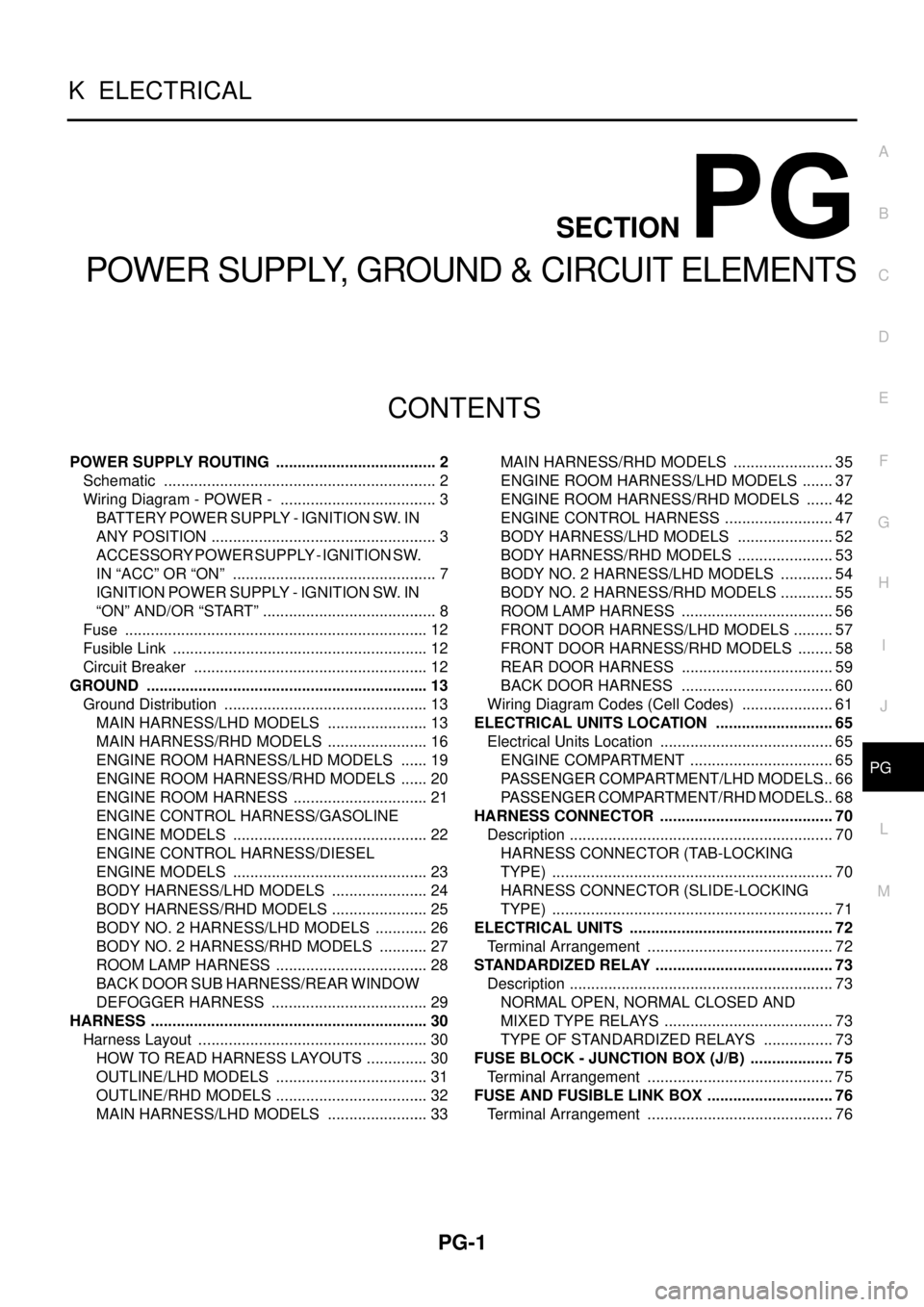
CONTENTS
C
D
E
F
G
H
I
J
L
M
SECTION
A
B
PG
POWER SUPPLY, GROUND & CIRCUIT ELEMENTS
POWER SUPPLY ROUTING ...................................... 2
Schematic ................................................................ 2
Wiring Diagram - POWER - ..................................... 3
BATTERY POWER SUPPLY - IGNITION SW. IN
ANY POSITION ..................................................... 3
ACCESSORY POWER SUPPLY - IGNITION SW.
IN “ACC” OR “ON” ................................................ 7
IGNITION POWER SUPPLY - IGNITION SW. IN
“ON” AND/OR “START” ......................................... 8
Fuse ....................................................................... 12
Fusible Link ............................................................ 12
Circuit Breaker ....................................................... 12
GROUND .................................................................. 13
Ground Distribution ................................................ 13
MAIN HARNESS/LHD MODELS ........................ 13
MAIN HARNESS/RHD MODELS ........................ 16
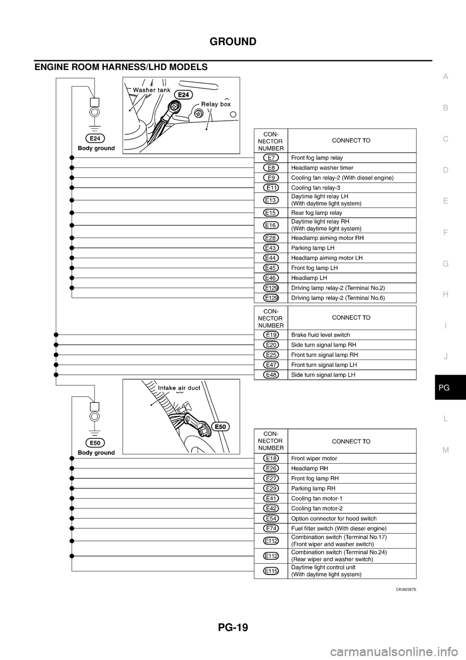
ENGINE ROOM HARNESS/LHD MODELS ....... 19
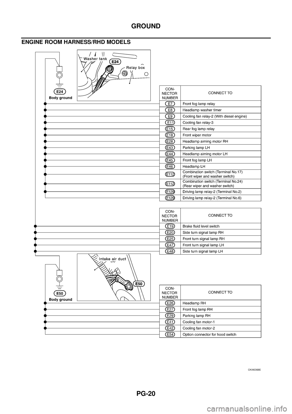
ENGINE ROOM HARNESS/RHD MODELS ....... 20
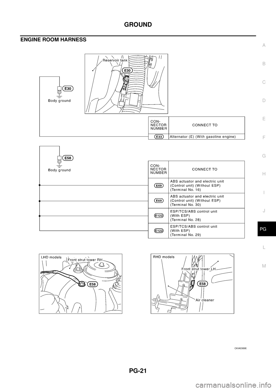
ENGINE ROOM HARNESS ................................ 21
ENGINE CONTROL HARNESS/GASOLINE
ENGINE MODELS .............................................. 22
ENGINE CONTROL HARNESS/DIESEL
ENGINE MODELS .............................................. 23
BODY HARNESS/LHD MODELS ....................... 24
BODY HARNESS/RHD MODELS ....................... 25
BODY NO. 2 HARNESS/LHD MODELS ............. 26
BODY NO. 2 HARNESS/RHD MODELS ............ 27
ROOM LAMP HARNESS .................................... 28
BACK DOOR SUB HARNESS/REAR WINDOW
DEFOGGER HARNESS ..................................... 29
HARNESS ................................................................. 30
Harness Layout ...................................................... 30
HOW TO READ HARNESS LAYOUTS ............... 30
OUTLINE/LHD MODELS .................................... 31
OUTLINE/RHD MODELS .................................... 32
MAIN HARNESS/LHD MODELS ........................ 33MAIN HARNESS/RHD MODELS ........................ 35
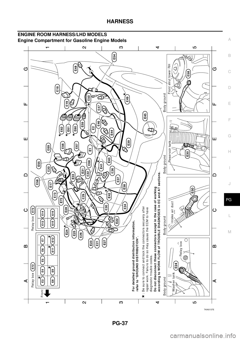
ENGINE ROOM HARNESS/LHD MODELS ........ 37
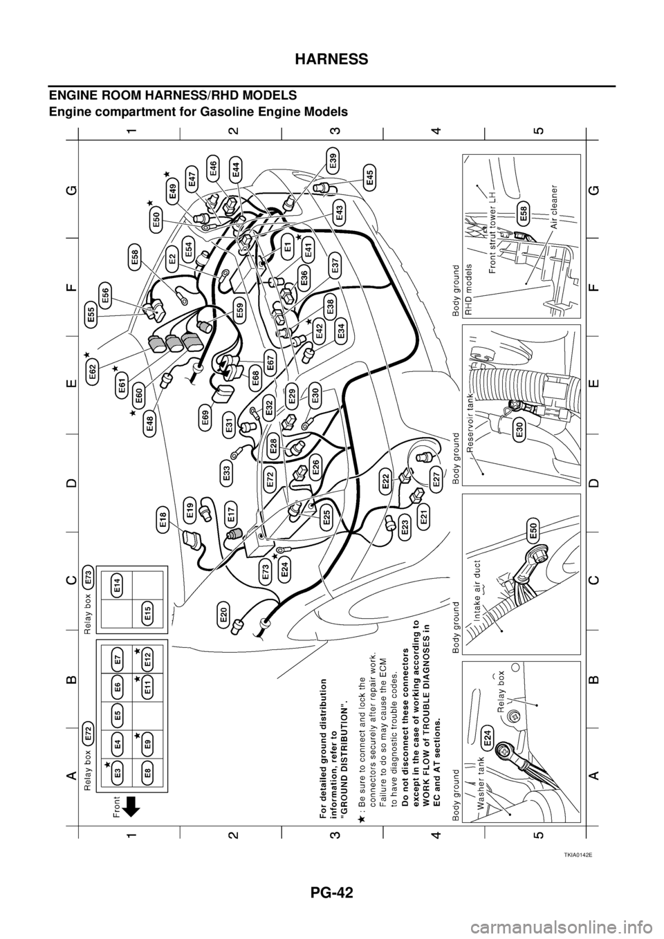
ENGINE ROOM HARNESS/RHD MODELS ....... 42
ENGINE CONTROL HARNESS .......................... 47
BODY HARNESS/LHD MODELS ....................... 52
BODY HARNESS/RHD MODELS ....................... 53
BODY NO. 2 HARNESS/LHD MODELS ............. 54
BODY NO. 2 HARNESS/RHD MODELS ............. 55
ROOM LAMP HARNESS .................................... 56
FRONT DOOR HARNESS/LHD MODELS .......... 57
FRONT DOOR HARNESS/RHD MODELS ......... 58
REAR DOOR HARNESS .................................... 59
BACK DOOR HARNESS .................................... 60
Wiring Diagram Codes (Cell Codes) ...................... 61
ELECTRICAL UNITS LOCATION ............................ 65
Electrical Units Location ......................................... 65
ENGINE COMPARTMENT .................................. 65
PASSENGER COMPARTMENT/LHD MODELS ... 66
PASSENGER COMPARTMENT/RHD MODELS ... 68
HARNESS CONNECTOR ......................................... 70
Description .............................................................. 70
HARNESS CONNECTOR (TAB-LOCKING
TYPE) .................................................................. 70
HARNESS CONNECTOR (SLIDE-LOCKING
TYPE) .................................................................. 71
ELECTRICAL UNITS ................................................ 72
Terminal Arrangement ............................................ 72
STANDARDIZED RELAY .......................................... 73
Description .............................................................. 73
NORMAL OPEN, NORMAL CLOSED AND
MIXED TYPE RELAYS ........................................ 73
TYPE OF STANDARDIZED RELAYS ................. 73
FUSE BLOCK - JUNCTION BOX (J/B) .................... 75
Terminal Arrangement ............................................ 75
FUSE AND FUSIBLE LINK BOX .............................. 76
Terminal Arrangement ............................................ 76
PG-30
HARNESS
HARNESS PFP:00011
Harness Layout EKS0032I
HOW TO READ HARNESS LAYOUTS
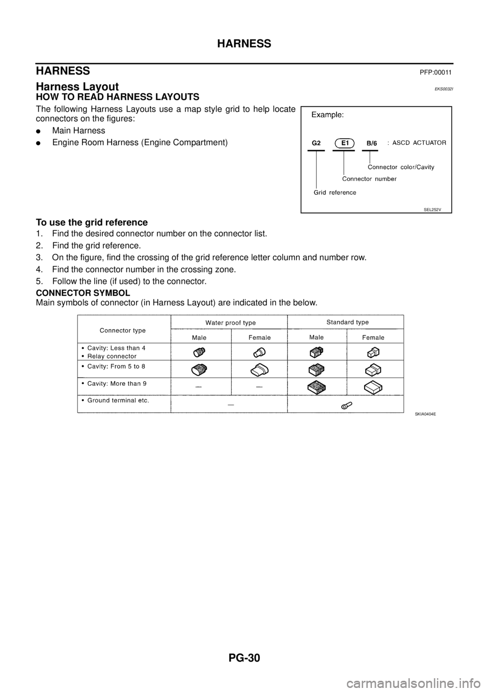
The following Harness Layouts use a map style grid to help locate
connectors on the figures:
�Main Harness
�Engine Room Harness (Engine Compartment)
To use the grid reference
1. Find the desired connector number on the connector list.
2. Find the grid reference.
3. On the figure, find the crossing of the grid reference letter column and number row.
4. Find the connector number in the crossing zone.
5. Follow the line (if used) to the connector.
CONNECTOR SYMBOL
Main symbols of connector (in Harness Layout) are indicated in the below.
SEL252V
SKIA0404E