Page 1821 of 4179
![NISSAN X-TRAIL 2003 Service Repair Manual DTC P2146, P2149 FUEL INJECTOR POWER SUPPLY
EC-1443
[YD (WITHOUT EURO-OBD)]
C
D
E
F
G
H
I
J
K
L
MA
EC
DTC P2146, P2149 FUEL INJECTOR POWER SUPPLYPFP:16600
Component DescriptionEBS0124X
The fuel inje NISSAN X-TRAIL 2003 Service Repair Manual DTC P2146, P2149 FUEL INJECTOR POWER SUPPLY
EC-1443
[YD (WITHOUT EURO-OBD)]
C
D
E
F
G
H
I
J
K
L
MA
EC
DTC P2146, P2149 FUEL INJECTOR POWER SUPPLYPFP:16600
Component DescriptionEBS0124X
The fuel inje](/manual-img/5/57404/w960_57404-1820.png)
DTC P2146, P2149 FUEL INJECTOR POWER SUPPLY
EC-1443
[YD (WITHOUT EURO-OBD)]
C
D
E
F
G
H
I
J
K
L
MA
EC
DTC P2146, P2149 FUEL INJECTOR POWER SUPPLYPFP:16600
Component DescriptionEBS0124X
The fuel injector is a small, precise solenoid valve. When the ECM
supplies a ground to the fuel injector circuit, the coil in the fuel injec-
tor is energized. The energized coil pulls the needle valve back and
allows fuel to flow through the fuel injector into the cylinder. The
amount of fuel injected depends upon the injection pulse duration.
Pulse duration is the length of time the fuel injector remains open.
The ECM controls the injection pulse duration based on engine fuel
needs.
CONSULT-II Reference Value in Data Monitor ModeEBS0124Y
Specification data are reference values.
ECM Terminals and Reference ValueEBS0124Z
Specification data are reference values and are measured between each terminal and ground.
CAUTION:
Do not use ECM ground terminals when measuring input/output voltage. Doing so may result in dam-
age to the ECM's transistor. Use a ground other than ECM terminals, such as the ground.
PBIB0465E
MONITOR ITEM CONDITION SPECIFICATION
MAIN INJ WID
�Engine: After warming up
�Shift lever: Neutral position
�Idle speedNo-load 0.68 - 0.78 msec
Blower fan switch: ON
Rear window defogger switch: ON0.78 - 0.88 msec
TERMI-
NAL
NO.WIRE
COLORITEM CONDITIONDATA
(DC Voltage and Pulse Signal)
4
5W/B
G/BFuel injector power supply
(For cylinder No. 1 and 4)
Fuel injector power supply
(For cylinder No. 2 and 3)[Engine is running]
�Warm-up condition
�Idle speed5 - 10V
[Engine is running]
�Warm-up condition
�Engine speed is 2,000 rpm5 - 10V
MBIB0883E
MBIB0884E
Page 1826 of 4179
![NISSAN X-TRAIL 2003 Service Repair Manual EC-1448
[YD (WITHOUT EURO-OBD)]
DTC P2147, P2148 FUEL INJECTOR CIRCUIT
DTC P2147, P2148 FUEL INJECTOR CIRCUITPFP:16600
Component DescriptionEBS01254
The fuel injector is a small, precise solenoid va NISSAN X-TRAIL 2003 Service Repair Manual EC-1448
[YD (WITHOUT EURO-OBD)]
DTC P2147, P2148 FUEL INJECTOR CIRCUIT
DTC P2147, P2148 FUEL INJECTOR CIRCUITPFP:16600
Component DescriptionEBS01254
The fuel injector is a small, precise solenoid va](/manual-img/5/57404/w960_57404-1825.png)
EC-1448
[YD (WITHOUT EURO-OBD)]
DTC P2147, P2148 FUEL INJECTOR CIRCUIT
DTC P2147, P2148 FUEL INJECTOR CIRCUITPFP:16600
Component DescriptionEBS01254
The fuel injector is a small, precise solenoid valve. When the ECM
supplies a ground to the fuel injector circuit, the coil in the fuel injec-
tor is energized. The energized coil pulls the needle valve back and
allows fuel to flow through the fuel injector into the intake cylinder.
The amount of fuel injected depends upon the injection pulse dura-
tion. Pulse duration is the length of time the fuel injector remains
open. The ECM controls the injection pulse duration based on
engine fuel needs.
CONSULT-II Reference Value in Data Monitor ModeEBS01255
Specification data are reference values.
ECM Terminals and Reference ValueEBS01256
Specification data are reference values and are measured between each terminal and ground.
CAUTION:
Do not use ECM ground terminals when measuring input/output voltage. Doing so may result in dam-
age to the ECM's transistor. Use a ground other than ECM terminals, such as the ground.
PBIB0465E
MONITOR ITEM CONDITION SPECIFICATION
MAIN INJ WID
�Engine: After warming up
�Shift lever: Neutral position
�Idle speedNo-load 0.68 - 0.78 msec
Blower fan switch: ON
Rear window defogger switch: ON0.78 - 0.88 msec
TERMI-
NAL
NO.WIRE
COLORITEM CONDITIONDATA
(DC Voltage and Pulse Signal)
4
5W/B
G/BFuel injector power supply
(For cylinder No. 1 and 4)
Fuel injector power supply
(For cylinder No. 2 and 3)[Engine is running]
�Warm-up condition
�Idle speed5 - 10V
[Engine is running]
�Warm-up condition
�Engine speed is 2,000 rpm5 - 10V
MBIB0883E
MBIB0884E
Page 1887 of 4179
![NISSAN X-TRAIL 2003 Service Repair Manual FUEL LEVEL SENSOR UNIT, FUEL FILTER AND FUEL PUMP ASSEMBLY
FL-9
[QR]
C
D
E
F
G
H
I
J
K
L
MA
FL
a. Using a screwdriver, separate the snap fit portion of bracket in
numerical order as shown in the fig NISSAN X-TRAIL 2003 Service Repair Manual FUEL LEVEL SENSOR UNIT, FUEL FILTER AND FUEL PUMP ASSEMBLY
FL-9
[QR]
C
D
E
F
G
H
I
J
K
L
MA
FL
a. Using a screwdriver, separate the snap fit portion of bracket in
numerical order as shown in the fig](/manual-img/5/57404/w960_57404-1886.png)
FUEL LEVEL SENSOR UNIT, FUEL FILTER AND FUEL PUMP ASSEMBLY
FL-9
[QR]
C
D
E
F
G
H
I
J
K
L
MA
FL
a. Using a screwdriver, separate the snap fit portion of bracket in
numerical order as shown in the figure.
CAUTION:
Put cloth or similar one on the edge of screwdriver not to
damage the inserted portion.
b. Pull out fuel pump, and disconnect harness connector.
2. Separate fuel filter and fuel level sensor unit as follows:
a. Fit a used O-ring into space between fuel level sensor unit and
fuel filter to release tabs.
NOTE:
For reference when reassembling, put a mating mark on outer
edges of fuel level sensor unit and fuel filter with some means
which cannot be erased by fuel.
b. Insert screwdriver to the gap between fuel filter and fuel level
sensor unit to separate them.
CAUTION:
Put cloth or similar one on the edge of screwdriver not to
damage the inserted portion.
3. Remove pressure regulator from fuel filter as follows:
a. Open and remove the clip.
b. Pull pressure regulator straight out during removal.
CAUTION:
�Avoid impacts such as falling during removal.
�Do not disassemble or adjust.
ASSEMBLY
Note the following, and assemble in the reverse order of disassembly.
�Install fuel filter and fuel pump with the tabs aligned. Make sure a click sound of secure engagement is
heard.
�Securely connect harness connector of fuel pump.
�Install pressure regulator O-ring.
CAUTION:
�When replacing, always use new O-ring.
�Handle it with bare hands. (Do not use gloves.)
�Visually check the O-ring, mounting parts and mating parts for foreign materials and flaws.
�Before installing, apply new engine oil.
�To avid damage, do not apply an excessive force (pulling or starching).
PBIC0242E
PBIC0243E
PBIC0244E
Page 1918 of 4179

CL-4
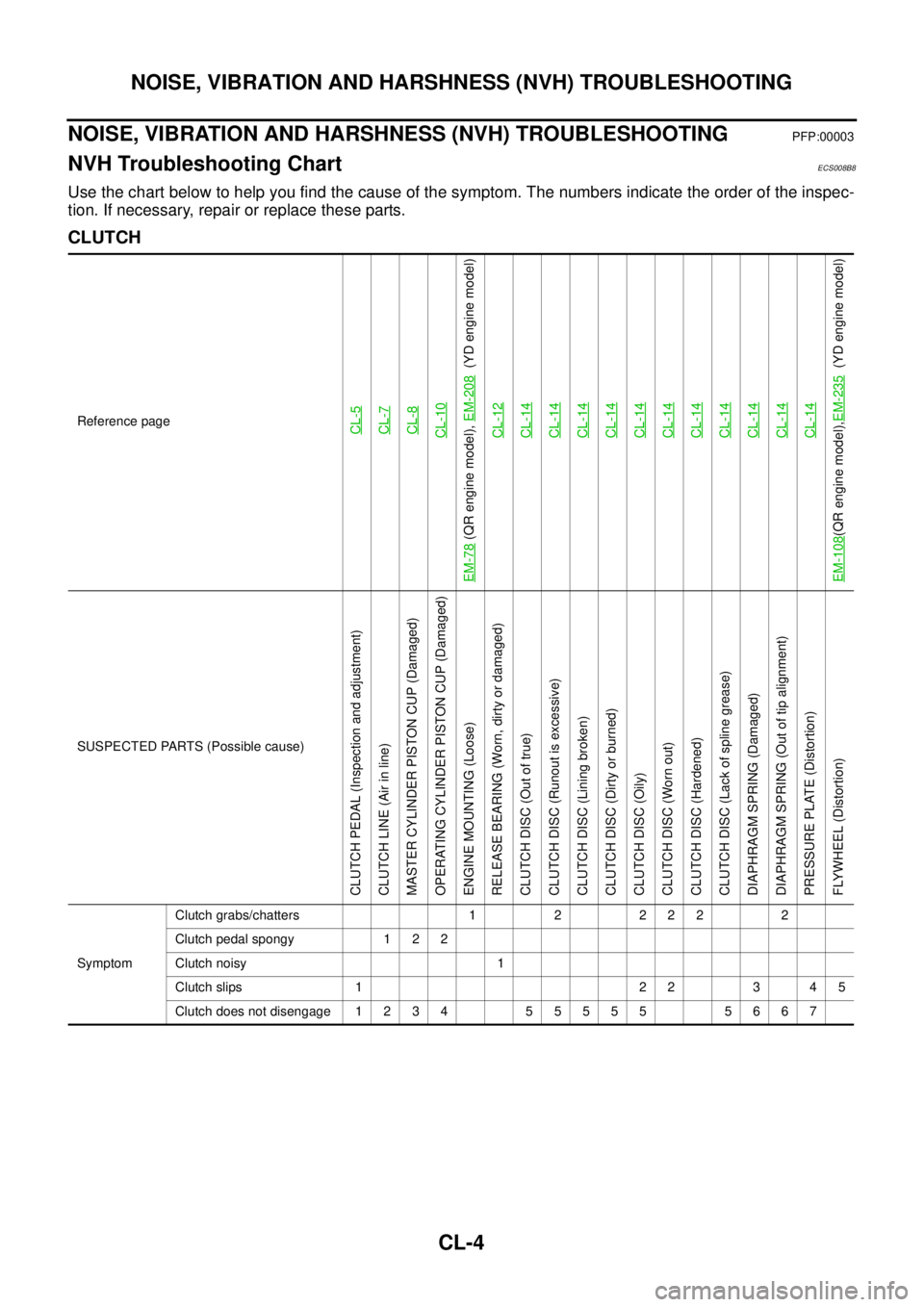
NOISE, VIBRATION AND HARSHNESS (NVH) TROUBLESHOOTING
NOISE, VIBRATION AND HARSHNESS (NVH) TROUBLESHOOTINGPFP:00003
NVH Troubleshooting ChartECS008B8
Use the chart below to help you find the cause of the symptom. The numbers indicate the order of the inspec-
tion. If necessary, repair or replace these parts.
CLUTCH
Reference pageCL-5CL-7CL-8CL-10
EM-78
(QR engine model), EM-208
(YD engine model)
CL-12
CL-14CL-14CL-14CL-14CL-14CL-14CL-14CL-14CL-14CL-14CL-14
EM-108
(QR engine model),EM-235
(YD engine model)
SUSPECTED PARTS (Possible cause)
CLUTCH PEDAL (Inspection and adjustment)
CLUTCH LINE (Air in line)
MASTER CYLINDER PISTON CUP (Damaged)
OPERATING CYLINDER PISTON CUP (Damaged)
ENGINE MOUNTING (Loose)
RELEASE BEARING (Worn, dirty or damaged)
CLUTCH DISC (Out of true)
CLUTCH DISC (Runout is excessive)
CLUTCH DISC (Lining broken)
CLUTCH DISC (Dirty or burned)
CLUTCH DISC (Oily)
CLUTCH DISC (Worn out)
CLUTCH DISC (Hardened)
CLUTCH DISC (Lack of spline grease)
DIAPHRAGM SPRING (Damaged)
DIAPHRAGM SPRING (Out of tip alignment)
PRESSURE PLATE (Distortion)
FLYWHEEL (Distortion)
SymptomClutch grabs/chatters 1 2 2 2 2 2
Clutch pedal spongy 1 2 2
Clutch noisy 1
Clutch slips 1 2 2 3 4 5
Clutch does not disengage 1 2 3 4 5 5 5 5 5 5 6 6 7
Page 1943 of 4179

M/T OIL
MT-11
D
E
F
G
H
I
J
K
L
MA
B
MT
M/T OILPFP:KLD20
Changing M/T OilECS008BR
DRAINING
1. Start engine and let it run to warm up transaxle.
2. Stop engine. Remove drain plug and drain oil.
3. Set a new gasket on drain plug and install it to transaxle. Refer to MT-19, "
CASE AND HOUSING COM-
PONENTS" , MT-24, "CASE AND HOUSING COMPONENTS" .
CAUTION:
Do not reuse gasket.
FILLING
1. Remove filler plug. Fill with new oil until oil level reaches the specified limit near filler plug mounting hole.
2. After refilling oil, check oil level. Assemble a new gasket to filler plug, then install it to transaxle. Refer to
MT-19, "
CASE AND HOUSING COMPONENTS" , MT-24, "CASE AND HOUSING COMPONENTS" .
CAUTION:
Do not reuse gasket.
Checking M/T OilECS008BS
OIL LEAKAGE AND OIL LEVEL
�Check that oil is not leaking from transaxle or around it.
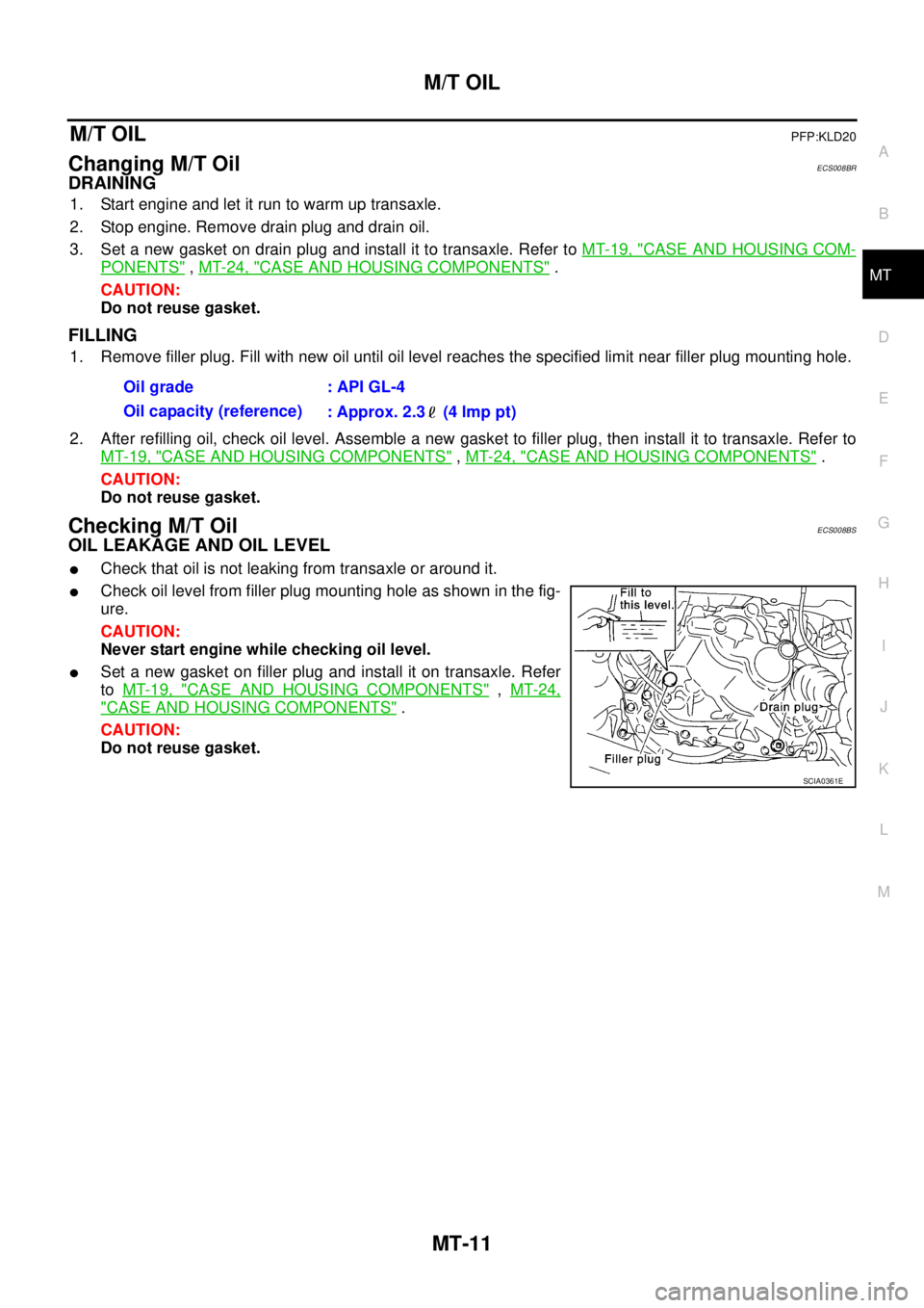
�Check oil level from filler plug mounting hole as shown in the fig-
ure.
CAUTION:
Never start engine while checking oil level.
�Set a new gasket on filler plug and install it on transaxle. Refer
to MT-19, "
CASE AND HOUSING COMPONENTS" , MT-24,
"CASE AND HOUSING COMPONENTS" .
CAUTION:
Do not reuse gasket.Oil grade : API GL-4
Oil capacity (reference)
: Approx. 2.3 (4 lmp pt)
SCIA0361E
Page 1949 of 4179

TRANSAXLE ASSEMBLY
MT-17
D
E
F
G
H
I
J
K
L
MA
B
MT
TRANSAXLE ASSEMBLYPFP:32010
Removal and InstallationECS008BX
REMOVAL
1. Remove air cleaner, air duct, and battery. Refer to EM-15, "Removal and Installation" ,EM-133, "Removal
and Installation"
2. Remove air breather hose. Refer to MT-16, "Removal and Installation" .
3. Remove clutch operating cylinder. Refer to CL-10, "
Removal and Installation" .
CAUTION:
Do not depress clutch pedal during removal procedure.
4. Disconnect control cable from transaxle. Refer to MT-15, "
Removal and Installation" .
5. Drain gear oil from transaxle. Refer to MT-11, "
DRAINING" .
6. Disconnect park/neutral position switch, back-up lamp switch, and ground harness connectors.
7. Remove exhaust front tube and the drive shaft. Refer to EX-2, "
Removal and Installation" .
8. Remove transfer. Refer to TF-55, "
Removal and Installation" .
9. Remove starter motor. Refer to SC-25, "
Removal and Installation" .
10. Place a jack onto transaxle.
CAUTION:
When setting jack, be careful not to bring it into contact with switch.
11. Remove center member, engine insulator and engine mount bracket. Refer to EM-78, "
ENGINE ASSEM-
BLY" (QR engine model) or EM-208, "ENGINE ASSEMBLY" (YD engine model).
12. Remove suspension members. Refer to FSU-12, "
FRONT SUSPENSION MEMBER" .
13. Support engine by placing a jack under oil pan.
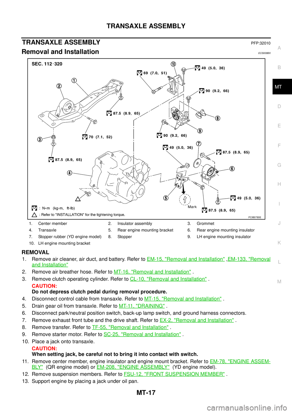
1. Center member 2. Insulator assembly 3. Grommet
4. Transaxle 5. Rear engine mounting bracket 6. Rear engine mounting insulator
7. Stopper rubber (YD engine model) 8. Stopper 9. LH engine mounting insulator
10. LH engine mounting bracket
PCIB0780E
Page 1950 of 4179
MT-18
TRANSAXLE ASSEMBLY
14. Remove bolts securing transaxle to engine.
15. Remove transaxle from vehicle.
INSTALLATION
Paying attention to the following items, install in the reverse order of removal.
�When installing transaxle to engine, tighten bolts to the specified torque.
CAUTION:
When installing transaxle, be careful not to bring transaxle input shaft into contact with clutch
cover.
QR engine model:
YD engine model:
�After installation, check oil level, and check for leaks and loose
mechanisms. Refer to MT-11, "
Checking M/T Oil" .
MTD0062D
Bolt No. 1 2 3 4 5 6
Quantity 2 1 1 2 2 2
“ ” mm (in)40
(1.57)75
(2.95)45
(1.77)40
(1.57)30
(1.18)40
(1.57)
Tightening torque
N·m (kg - m, ft- lb)74.5
(7.6, 55)42.7
(4.4, 31)35.3
(3.6, 26 )
SCIA0353E
Bolt No. 1 2 3 4 5 6
Quantity 2 2 1 1 3 1
“ ” mm (in)55
(2.17)50
(2.76)120
(4.72)45
(1.77)40
(1.57)35
(1.38)
Tightening torque
N·m (kg - m, ft- lb)44
(4.5, 32)33.5
(3.4, 25)
SCIA0748E
Page 2030 of 4179
MT-98
SERVICE DATA AND SPECIFICATIONS (SDS)
SERVICE DATA AND SPECIFICATIONS (SDS)PFP:00030
General SpecificationsECS008CE
TRANSAXLE
Engine QR20DE QR25DE YD22DDTi
Transaxle model RS5F51A RS6F51A
Model code number EQ000 EQ008 EQ068
Number of speed 5 6
Synchromesh typeWarner
Shift pattern
5 speed
6 speed
Gear ratio 1st 3.500 3.416 3.500
2nd 1.944
3rd 1.258
4th 0.947
5th 0.772 0.733 0.772
6th — 0.630
Reverse 3.374 3.252 3.374
Number of teeth Input gear 1st 14 12 14
2nd 18
3rd 31
4th 38
5th 444544
6th — 46
Reverse141214
Main gear 1st 49 41 49
2nd 35
3rd 39
4th 36
5th 343334
6th — 29
Reverse 38
Reverse idler
gearFront 37
Rear 46 38 46
Oil capacity
(Imp pt)2.3 (4)
SCIA0821E
SCIA0955E