Page 2943 of 4179

STEERING WHEEL
PS-7
C
D
E
F
H
I
J
K
L
MA
B
PS
STEERING WHEELPFP:48430
On-Vehicle Inspection and ServiceEGS0004E
PLAY INSPECTION
1. Turn steering wheel to straight-ahead position. Start engine and lightly turn steering wheel clockwise and
counter clockwise until front wheels start moving. Measure travel to starting point on circumference of
steering wheel.
2. If play is outside specifications, check following parts for proper installation: steering gear assembly, front
suspension, axles, and steering column.
�Check steering wheel for vertical, horizontal, or axial play.
�Lift vehicle and check steering gear mounting bolts and nuts for looseness.
NEUTRAL POSITION INSPECTION
�After the wheel alignment inspection, carry out the neutral position inspection. Refer to FSU-6, "Wheel
Alignment" .
�Before removing steering wheel, check steering gear neutral position.
1. Set vehicle to straight-ahead position, and check that steering wheel is in neutral position.
2. If it is not in neutral position, remove steering wheel, and install again in properly.
3. If it is not adjusted within two teeth from center of gear, loosen tie rod lock nut. Then turn it to opposite
direction to adjust until amount of left and right becomes equal.
STEERING TORQUE CHECK
1. Stop vehicle on a dry flat paved road and apply parking brake.
2. Start engine and wait until power steering fluid warms up. Using
a preload gauge (SST), check rotating torque of steering wheel.
3. If torque is outside specifications, check rack sliding torque and
oil pump relief pressure.
STEERING ANGLE INSPECTION
�After toe-in inspection, check steering angle. Place front wheels
on turning radius gauges and rear wheels on stands. Level the
vehicle. Check maximum inner and outer wheel steering angles
for LH and RH road wheels.Steering wheel play inspection standard : 0 - 35 mm (0 - 1.38 in)
Steering wheel axial endplay : 0 mm (0 in)
Tightening torque : 140 - 160 N·m (15 - 16 kg-m, 104 - 118 ft-lb)
Steering torque:
706 N·cm (72 kg-cm, 62 in-lb) or less
Rack sliding torque:
153 - 240 N (15.5 - 24.5 kg, 34.3 - 54.2 lb)
Oil pump relief hydraulic pressure:
8,000 - 8,800 kPa (81.4 - 87.3 bar, 83 - 89 kg/cm
2 , 1,180 - 1,266 psi)
STA0005D
FAA0016D
Page 2944 of 4179

PS-8
STEERING WHEEL
�Start engine. With engine at idle, turn steering wheel from stop
to stop and measure steering angles.
�If angles are outside specification, measure rack stroke.
�If rack stroke is outside of specification, disassemble steering
gear to check rack stroke.
�Steering angles are not adjustable. If any of steering angles is different from specified value, check steer-
ing gear, the column and the front suspension components for wear or damage. If any abnormality exists,
replace the malfunctioning parts.
Removal and InstallationEGS0004F
REMOVAL
1. Remove air bag module. Refer to SRS-30, "DRIVER AIR BAG MODULE" .
2. Remove horn connector.
3. Remove steering wheel mounting nut and paint mating marks on steering wheel body and top of column
shaft.
4. Using a steering wheel puller (SST), remove steering wheel.
INSTALLATION
Paying attention to following items, install in the reverse order of removal.
NOTE:
�When reconnecting spiral cable, fix cable with a tape so that fixing case and rotating part keep aligned.
This will omit neutral position alignment procedure during spiral cable installation.
�Neutral position (refer to figure)... Gently turn spiral cable clock-
wise until it comes to the stop. Then turn it counter clockwise
(approximately 3.0 turns) until centering mark is aligned with
adjustment mark. (Service part is fixed in neutral position with
stopper. It can be installed onto steering wheel without align-
ment once stopper is removed.)
CAUTION:
�Place steering wheel as follows: Front wheels in straight-
ahead position. R mark on the cancel claw faces down. 3
bosses align with 3 holes behind steering wheel assembly.
Check that spiral cable is placed in neutral position and that
locating pin on the left of the spiral cable is aligned with the
locating pinhole behind the steering wheel assembly.
�Do not rotate spiral cable more than necessary. Do not tighten them excessively. (The cable may
be torn off.)
�After installation, check system for proper operation by observing air bag warning lamp.
�If air bag indicator indicates any abnormal condition, use self-diagnosis function or CONSULT to
reset or cancel memory.Inner wheel Minimum : 36°
Nominal : 39°
Maximum : 40°
Outer wheel : 31°
Rack stroke : 66.5 mm (2.618 in)
SGIA0055E
SGIA0080E
SGIA0096E
Page 2960 of 4179

PS-24
POWER STEERING OIL PUMP
POWER STEERING OIL PUMPPFP:49110
On-Vehicle Inspection and ServiceEGS000AF
OIL PUMP PULLEY HYDRAULIC PRESSURE INSPECTION
Before starting following procedure, check tension of belt.
1. Raise vehicle. Connect oil pressure gauge between oil pump
discharge connector and high pressure hose. Then bleed the
hydraulic circuit.
2. Start engine. Run engine until oil temperature reaches 50°C -
80°C (122 - 176°F)
CAUTION:
�Leave valve of hydraulic pressure gauge fully open while
starting and running engine. If engine is started with
valve closed, hydraulic pressure in oil pump goes up.
This will relief pressure along with abnormal increase of
oil temperature.
�Care must be taken to keep hose clear of belt and other parts when engine is started.
3. Fully close hydraulic pressure gauge valve with engine at idle. Measure relief pressure.
4. After measurement, open valve slowly.
CAUTION:
Never keep valve closed for 15 seconds or longer.
�If relief pressure is outside specification, disassemble and service oil pump. Refer to PS-25, "Disas-
sembly and Assembly(QR20DE and QR25DE engine models)" .
5. After inspection, remove oil pressure gauge from hydraulic circuit. Add fluid. Be sure to bleed the system
completely. Refer to PS-6, "
Bleeding Hydraulic System"
Removal and Installation (QR20DE and QR25DE engine models)EGS000AG
REMOVAL
1. Loosen adjusting screw and oil pump mounting bolt. Then, remove belt.
2. Remove union bolt and hose for oil pump.
3. Remove oil pump bracket attaching bolt.
4. Remove oil pump from vehicle.
INSTALLATION
Paying attention to following items, install in the reverse order of removal.
�After installation, adjust belt tension. Refer to EM-13, "DRIVE BELTS" .
�After installation, be sure to bleed system. Refer to PS-6, "Bleeding Hydraulic System" . Relief pressure specification:
8,000 - 8,800 kPa (81.4 - 87.3 bar, 83 - 89 kg/cm
2 , 1,180 - 1,266 psi)
SST834-H
Page 2961 of 4179
EGS000AH
INSPECTION BEFORE DISASSEMBLY
Disassemble the power steering oil pump only i")
POWER STEERING OIL PUMP
PS-25
C
D
E
F
H
I
J
K
L
MA
B
PS
Disassembly and Assembly(QR20DE and QR25DE engine models)EGS000AH
INSPECTION BEFORE DISASSEMBLY
Disassemble the power steering oil pump only if the following items
are found.
�Oil leak from any point shown in the figure
�Deformed or damaged pulley
�Poor performance
DISASSEMBLY
1. Fix power steering pump in a vise.
CAUTION:
When fixing pump in a vise, use aluminum plates to protect steering pump mounting surface.
2. Remove rear bracket mounting bolts. Remove rear bracket from rear body.
3. Remove three front bracket attaching bolts and remove front bracket from casing.
4. Remove four rear body attaching bolts and remove rear body from casing.
5. Remove body seal from casing.
6. Remove side plate (rear) from cartridge. Remove side plate inner and outer seals from side plate (rear).
1. Pulley 2. Front bracket 3. Drive shaft seal
4. Casing 5. Inlet connector seal 6. Inlet connector
7. Flow control valve spring 8. Flow control A valve 9. Dowel pin
10. Flow control B valve assembly 11. Side plate (front) 12. Cartridge
13. Rotor 14. Vane 15. Rotor snap ring
16. Side plate (rear) 17. Side plate inner seal 18. Side plate outer seal
19. Body seal 20. Rear body 21. Rear bracket
SGIA0645E
SST984A
Page 2964 of 4179

PS-28
POWER STEERING OIL PUMP
9. Connect rotor snap ring to slit of pulley shaft, using a hammer
and a 10-mm socket.
CAUTION:
� Rotor snap ring is not reusable. Never reuse rotor snap
ring.
�Be careful not to damage rotor and pulley shaft.
�If rotor is damaged, power steering pump assembly must
be replaced.
10. Align dowel pin A on flow control valve A with notch B in side
plate (rear) as shown. Install side plate (rear) to cartridge.
11. Apply DEXRON
TM III or equivalent to body seal. Install it to cas-
ing.
CAUTION:
Body seal is not reusable. Never reuse body seal.
12. Apply DEXRON
TM III or equivalent to side plate inner and outer
seals. Install them to side plate (rear).
CAUTION:
Side plate inner and outer seals are not reusable. Never
reuse side plate inner and outer seals.
13. Fix power steering pump in a vise.
CAUTION:
When fixing pump in a vise, use aluminum plates to protect
steering pump mounting surface.
14. Attach rear body to casing and tighten four mounting bolts diag-
onally to specified torque.
15. Install rear bracket to rear body. Tighten mounting bolts to specified torque.
16. Connect front bracket to casing and tighten mounting bolts (3) to specified torque.
17. Connect inlet connector seal to inlet connector slit. Install inlet connector to casing with attaching bolts.
CAUTION:
Inlet connector seal is not reusable. Never reuse inlet connector seal.
Removal and Installation (YD22DDTi engine model)EGS000AI
1. Remove chain case cover.
SGIA0063E
SGIA0064E
SGIA0065E
SST884C
Page 2965 of 4179
POWER STEERING OIL PUMP
PS-29
C
D
E
F
H
I
J
K
L
MA
B
PS
2. Revolving crank pulley, set tool.
3. Fix tool with chain cover fixing bolts.
4. Using suitable tool, remove sprocket fixing nut and washer.
CAUTION:
Do not remove Tool while power steering oil pump is
removed.
5. Remove power steering pump fixing bolts, then remove it.
6. Apply Gasket to the installation surface of the engine chain case
cover as shown in the figure before installing the chain case
cover to the engine.
7. Bleed air after installation. Refer to PS-6, "
Bleeding Hydraulic
System"
SST885C
SST886C
SST890C
Page 2966 of 4179
PS-30
POWER STEERING OIL PUMP
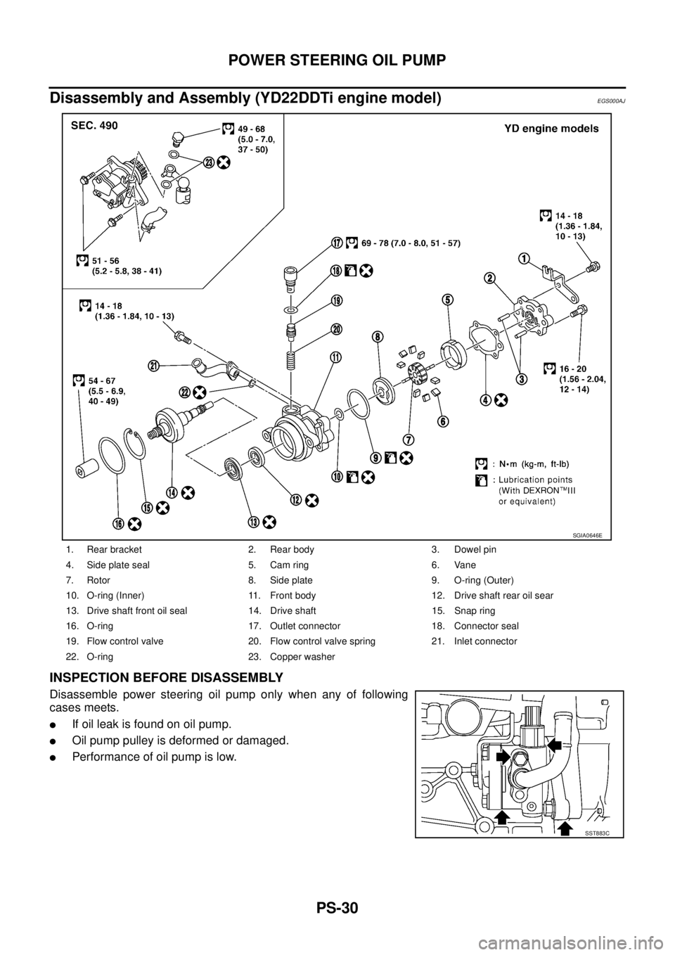
Disassembly and Assembly (YD22DDTi engine model)EGS000AJ
INSPECTION BEFORE DISASSEMBLY
Disassemble power steering oil pump only when any of following
cases meets.
�If oil leak is found on oil pump.
�Oil pump pulley is deformed or damaged.
�Performance of oil pump is low.
1. Rear bracket 2. Rear body 3. Dowel pin
4. Side plate seal 5. Cam ring 6. Vane
7. Rotor 8. Side plate 9. O-ring (Outer)
10. O-ring (Inner) 11. Front body 12. Drive shaft rear oil sear
13. Drive shaft front oil seal 14. Drive shaft 15. Snap ring
16. O-ring 17. Outlet connector 18. Connector seal
19. Flow control valve 20. Flow control valve spring 21. Inlet connector
22. O-ring 23. Copper washer
SGIA0646E
SST883C
Page 2970 of 4179
PS-34
HYDRAULIC LINE
HYDRAULIC LINEPFP:49721
Components (QR20DE and QR25DE engine models)EGS0004O
CAUTION:
Securely insert harness connector to oil pressure sensor.
QR20DE LH MODEL
SGIA0944E

EGS0004O
CAUTION:
Securely insert harness connector to oil pressure sensor.
QR20DE LH MODEL
SGIA0944E")