Page 1881 of 4179
![NISSAN X-TRAIL 2003 Service Repair Manual FUEL SYSTEM
FL-3
[QR]
C
D
E
F
G
H
I
J
K
L
MA
FL
FUEL SYSTEMPFP:17503
Checking Fuel LinesEBS00KOS
Inspect fuel lines, filler cap and tank for improper attachment, leaks,
cracks, damage, loose connect](/manual-img/5/57404/w960_57404-1880.png "NISSAN X-TRAIL 2003 Service Repair Manual FUEL SYSTEM
FL-3
[QR]
C
D
E
F
G
H
I
J
K
L
MA
FL
FUEL SYSTEMPFP:17503
Checking Fuel LinesEBS00KOS
Inspect fuel lines, filler cap and tank for improper attachment, leaks,
cracks, damage, loose connect")
FUEL SYSTEM
FL-3
[QR]
C
D
E
F
G
H
I
J
K
L
MA
FL
FUEL SYSTEMPFP:17503
Checking Fuel LinesEBS00KOS
Inspect fuel lines, filler cap and tank for improper attachment, leaks,
cracks, damage, loose connections, chafing or deterioration.
If necessary, repair or replace damaged parts.
General PrecautionsEBS011T7
WARNING:
When replacing fuel line parts, be sure to observe the following.
�Put a “CAUTION: INFLAMMABLE” sign in the workshop.
�Be sure to work in a well ventilated area and furnish workshop with a CO2 fire extinguisher.
�Do not smoke while servicing fuel system. Keep open flames and sparks away from the work area.
CAUTION:
�Before removing fuel line parts, perform the following procedures:
–Put drained fuel in an explosion-proof container and put the lid on securely. Keep the container in
safe area.
–Release fuel pressure from the fuel lines. Refer to EC-48, "FUEL PRESSURE RELEASE" (WITH
EURO-OBD) or EC-510, "
FUEL PRESSURE RELEASE" (WITHOUT EURO-OBD).
–Disconnect negative battery terminal.
�Always replace O-rings and clamps with new ones.
�Do not kink or twist tubes when they are being installed.
�Do not tighten hose clamps excessively to avoid damaging hoses.
�After connecting fuel tube quick connectors, make sure
quick connectors are secure.
Ensure that connector and resin tube do not contact any
adjacent parts.
�After installing tubes, check if there are no fuel leaks at con-
nections in the following steps.
–Apply fuel pressure to fuel lines with turning ignition switch
“ON” (with engine stopped). Then check for fuel leaks at
connections.
–Start engine and rev it up and check for fuel leaks at con-
nections.
�For servicing “Evaporative Emission System” parts, refer to
EC-473, "
EVAPORATIVE EMISSION SYSTEM" (WITH EURO-
ODB) or EC-865, "
EVAPORATIVE EMISSION SYSTEM"
(WITHOUT EURO-OBD).
SMA803A
SBIA0504E
Page 1886 of 4179
FL-8
[QR]
FUEL LEVEL SENSOR UNIT, FUEL FILTER AND FUEL PUMP ASSEMBLY
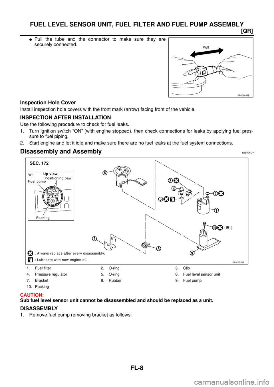
�Pull the tube and the connector to make sure they are
securely connected.
Inspection Hole Cover
Install inspection hole covers with the front mark (arrow) facing front of the vehicle.
INSPECTION AFTER INSTALLATION
Use the following procedure to check for fuel leaks.
1. Turn ignition switch “ON” (with engine stopped), then check connections for leaks by applying fuel pres-
sure to fuel piping.
2. Start engine and let it idle and make sure there are no fuel leaks at the fuel system connections.
Disassembly and AssemblyEBS00KOV
CAUTION:
Sub fuel level sensor unit cannot be disassembled and should be replaced as a unit.
DISASSEMBLY
1. Remove fuel pump removing bracket as follows:
PBIC1653E
1. Fuel filter 2. O-ring 3. Clip
4. Pressure regulator 5. O-ring 6. Fuel level sensor unit
7. Bracket 8. Rubber 9. Fuel pump
10. Packing
PBIC2259E
Page 1891 of 4179
FUEL TANK
FL-13
[QR]
C
D
E
F
G
H
I
J
K
L
MA
FL
CAUTION:
Use genuine fuel filler tube mounting bolts or equivalent. Make sure to tighten them to the speci-
fied torque.
�To connect quick connector, refer to FL-7, "Quick Connector" .
INSPECTION AFTER INSTALLATION
Use the following procedure to check for fuel leaks.
1. Turn ignition switch “ON” (with engine stopped), and check connections for leaks by applying fuel pres-
sure to fuel piping.
2. Start engine and let it idle and make sure there are no fuel leaks at the fuel system tube and hose connec-
tions.
Page 1896 of 4179
![NISSAN X-TRAIL 2003 Service Repair Manual FL-18
[YD22DDTi]
FUEL FILTER
Air BleedingEBS00BLB
After fuel filter is replaced and after fuel system components are
removed/installed, bleed air from fuel line as follows:
�Move priming pump up and](/manual-img/5/57404/w960_57404-1895.png "NISSAN X-TRAIL 2003 Service Repair Manual FL-18
[YD22DDTi]
FUEL FILTER
Air BleedingEBS00BLB
After fuel filter is replaced and after fuel system components are
removed/installed, bleed air from fuel line as follows:
�Move priming pump up and")
FL-18
[YD22DDTi]
FUEL FILTER
Air BleedingEBS00BLB
After fuel filter is replaced and after fuel system components are
removed/installed, bleed air from fuel line as follows:
�Move priming pump up and down to bleed air from fuel path.
�When air is bled, pumping of priming pump becomes heavy stop
operation at that time.
�Crank engine until it starts. Do not crank engine for more than
30 seconds.
�If engine does not start, stop cranking and repeat step 1 above.
�If engine does not operate smoothly after it has started, race it
two or three times.
�If air cannot be bled easily (pumping of priming pump does not
become heavy), disconnect feed-side of hose between fuel filter and electronically controlled fuel pump.
After that, operate priming pump and confirm that fuel comes out.
CAUTION:
Prepare a tray to collect fuel. Prevent fuel from adhering to rubber parts, especially the engine
mounting insulator.
Draining Water from Fuel FilterEBS00MRU
1. Prepare a tray at the drain hose open end.
2. Loosen drain cock, and operate priming pump to drain water
from fuel filter.
CAUTION:
�Water in filter is drained with fuel. Prepare larger capacity
pan than fuel filter volume.
�Drained water is mixed with fuel. Prevent fuel from adher-
ing to rubber parts such as engine mounting insulator.
3. After draining, close drain cock by hand.
CAUTION:
If drain cock is tightened excessively, it may be damaged
and fuel will leak. Do not use tools to tighten drain cock.
4. Bleed air in fuel piping. Refer to FL-18, "
Air Bleeding" .
5. Start engine and make sure there is no fuel leakage.
SBIA0137E
SBIA0138E
Page 1943 of 4179

M/T OIL
MT-11
D
E
F
G
H
I
J
K
L
MA
B
MT
M/T OILPFP:KLD20
Changing M/T OilECS008BR
DRAINING
1. Start engine and let it run to warm up transaxle.
2. Stop engine. Remove drain plug and drain oil.
3. Set a new gasket on drain plug and install it to transaxle. Refer to MT-19, "
CASE AND HOUSING COM-
PONENTS" , MT-24, "CASE AND HOUSING COMPONENTS" .
CAUTION:
Do not reuse gasket.
FILLING
1. Remove filler plug. Fill with new oil until oil level reaches the specified limit near filler plug mounting hole.
2. After refilling oil, check oil level. Assemble a new gasket to filler plug, then install it to transaxle. Refer to
MT-19, "
CASE AND HOUSING COMPONENTS" , MT-24, "CASE AND HOUSING COMPONENTS" .
CAUTION:
Do not reuse gasket.
Checking M/T OilECS008BS
OIL LEAKAGE AND OIL LEVEL
�Check that oil is not leaking from transaxle or around it.
�Check oil level from filler plug mounting hole as shown in the fig-
ure.
CAUTION:
Never start engine while checking oil level.
�Set a new gasket on filler plug and install it on transaxle. Refer
to MT-19, "
CASE AND HOUSING COMPONENTS" , MT-24,
"CASE AND HOUSING COMPONENTS" .
CAUTION:
Do not reuse gasket.Oil grade : API GL-4
Oil capacity (reference)
: Approx. 2.3 (4 lmp pt)
SCIA0361E
Page 1949 of 4179

TRANSAXLE ASSEMBLY
MT-17
D
E
F
G
H
I
J
K
L
MA
B
MT
TRANSAXLE ASSEMBLYPFP:32010
Removal and InstallationECS008BX
REMOVAL
1. Remove air cleaner, air duct, and battery. Refer to EM-15, "Removal and Installation" ,EM-133, "Removal
and Installation"
2. Remove air breather hose. Refer to MT-16, "Removal and Installation" .
3. Remove clutch operating cylinder. Refer to CL-10, "
Removal and Installation" .
CAUTION:
Do not depress clutch pedal during removal procedure.
4. Disconnect control cable from transaxle. Refer to MT-15, "
Removal and Installation" .
5. Drain gear oil from transaxle. Refer to MT-11, "
DRAINING" .
6. Disconnect park/neutral position switch, back-up lamp switch, and ground harness connectors.
7. Remove exhaust front tube and the drive shaft. Refer to EX-2, "
Removal and Installation" .
8. Remove transfer. Refer to TF-55, "
Removal and Installation" .
9. Remove starter motor. Refer to SC-25, "
Removal and Installation" .
10. Place a jack onto transaxle.
CAUTION:
When setting jack, be careful not to bring it into contact with switch.
11. Remove center member, engine insulator and engine mount bracket. Refer to EM-78, "
ENGINE ASSEM-
BLY" (QR engine model) or EM-208, "ENGINE ASSEMBLY" (YD engine model).
12. Remove suspension members. Refer to FSU-12, "
FRONT SUSPENSION MEMBER" .
13. Support engine by placing a jack under oil pan.
1. Center member 2. Insulator assembly 3. Grommet
4. Transaxle 5. Rear engine mounting bracket 6. Rear engine mounting insulator
7. Stopper rubber (YD engine model) 8. Stopper 9. LH engine mounting insulator
10. LH engine mounting bracket
PCIB0780E
Page 2052 of 4179

AT-16
A/T FLUID
A/T FLUIDPFP:KLE40
Checking A/T FluidECS004Q7
1. Warm up engine.
2. Check for A/T fluid leakage.
3. Before driving, A/T fluid level can be checked at A/T fluid tem-
peratures of 30 to 50°C (86 to 122°F) using “COLD” range on A/
T fluid level gauge.
a. Park vehicle on level surface and set parking brake.
b. Start engine and move selector lever through each gear posi-
tion. Leave selector lever in “P” position.
c. Check A/T fluid level with engine idling.
d. Remove A/T fluid level gauge and note reading. If level is at low
side of either range, and A/T fluid to the A/T fluid charging pipe.
CAUTION:
When wiping away the A/T fluid level gauge, always use
lint-free paper, not a cloth one.
e. Re-insert A/T fluid level gauge into A/T fluid charging pipe as far
as it will go.
CAUTION:
Firmly fix the A/T fluid level gauge to the A/T fluid charging
pipe using a stopper attached.
f. Remove A/T fluid level gauge and note reading. If reading is at
low side of range, add A/T fluid to the A/T fluid charging pipe.
CAUTION:
Do not overfill.
4. Drive vehicle for approximately 5 minutes in urban areas.
5. Recheck A/T fluid level at A/T fluid temperatures of 50 to 80°C (122 to 176°F) using “HOT” range on A/T
fluid level gauge.
CAUTION:
�When wiping away the A/T fluid level gauge, always use lint-free paper, not a cloth one.
�Firmly fix the A/T fluid level gauge to the A/T fluid charging pipe using a stopper attached.
SMA146B
SMA827CA
SMA051D
Page 2070 of 4179

*2: Spare for accelerator pedal position signal
*3: If these input and output sign")
AT-34
OVERALL SYSTEM
Input/Output Signal of TCMECS00CTC
*1: Spare for vehicle speed sensor·A/T (revolution sensor)
*2: Spare for accelerator pedal position signal
*3: If these input and output signals are different, the TCM triggers the fail-safe function.
*4: Used as a condition for starting self-diagnostics; if self-diagnostics are not started, it is judged that there is some kind of error.
*5: Input by CAN communications.
*6: Output by CAN communications.
Line Pressure ControlECS004QF
�TCM has various line pressure control characteristics to match the driving conditions.
�An ON-OFF duty signal is sent to the line pressure solenoid valve based on TCM characteristics.
�Hydraulic pressure on the clutch and brake is electronically controlled through the line pressure solenoid
valve to accommodate engine torque. This results in smooth shift operation.
NORMAL CONTROL
The line pressure to throttle opening characteristics is set for suitable
clutch operation.
Control itemLine
pressure
controlVehicle
speed
controlShift
controlLock-up
controlEngine
brake
controlFail-safe
function
(*3)Self-diag-
nostics
function
InputAccelerator pedal position signalXXXXXXX
Vehicle speed sensor A/T
(Revolution sensor)XXXX XX
Vehicle speed sensor MTR
(*1)XXXX X
Closed throttle position signal
(*5)(*2) X (*2) X X (*4) X
Wide open throttle position signal
(*5)(*2) X (*2) X (*4) X
Engine speed signal X X
PNP switch XXXXXX(*4) X
Stop lamp switch signal
(*5)XXX(*4) X
A/T fluid temperature sensors X X X X X
TCM power supply voltage signal XX
Out-
putShift solenoid valve A/B X X X
Line pressure solenoid X X X
Torque converter clutch solenoid
valveXXX
Overrun clutch solenoid valve X X X X
O/D OFF indicator lamp
(*6)X
SAT003J