2003 NISSAN X-TRAIL check engine
[x] Cancel search: check enginePage 2854 of 3066
RSU-2
PRECAUTIONS
PRECAUTIONS
PFP:00001
CautionEES0007C
lFinal tightening of bushings must be carried out under unladen condition with tires on the ground. Oil will
shorten life of bushings. Be sure to wipe off any spilled oil.
l“Unladen condition” means that fuel, coolant and lubricant are full and ready for drive. However, spare tire,
jack, and hand tools should be unloaded.
lAfter installing the removed suspension parts, always check wheel alignment and adjust if necessary.
lReplace the caulking nut with a new one. Install a new nut without wiping the oil off before tightening.
Precautions for Brake SystemEES000JB
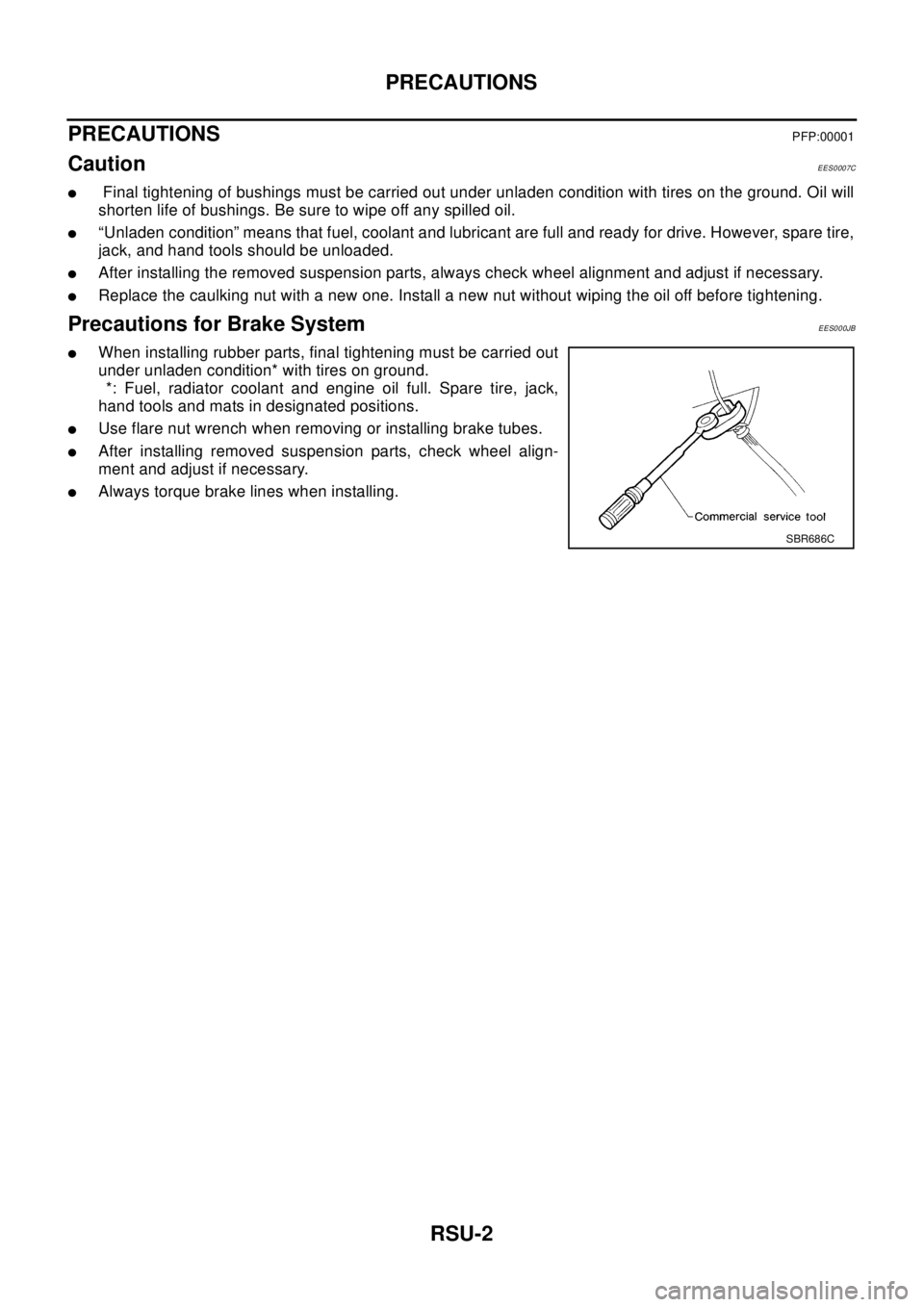
lWhen installing rubber parts, final tightening must be carried out
under unladen condition* with tires on ground.
*: Fuel, radiator coolant and engine oil full. Spare tire, jack,
hand tools and mats in designated positions.
lUse flare nut wrench when removing or installing brake tubes.
lAfter installing removed suspension parts, check wheel align-
ment and adjust if necessary.
lAlways torque brake lines when installing.
SBR686C
Page 2873 of 3066
SC-1
STARTING & CHARGING SYSTEM
K ELECTRICAL
CONTENTS
C
D
E
F
G
H
I
J
L
M
SECTION
A
B
SC
STARTING & CHARGING SYSTEM
PRECAUTIONS .......................................................... 2
Precautions for Supplemental Restraint System
(SRS) “AIR BAG” and “SEAT BELT PRE-TEN-
SIONER” .................................................................. 2
Wiring Diagrams and Trouble Diagnosis .................. 2
BATTERY .................................................................... 3
How to Handle Battery ............................................. 3
METHODS OF PREVENTING OVER-DIS-
CHARGE ............................................................... 3
CHECKING ELECTROLYTE LEVEL .................... 3
SPECIFIC GRAVITY CHECK ............................... 4
Battery Test and Charging Chart .............................. 5
CHART I ................................................................ 5
CHART II ............................................................... 6
A: SLOW CHARGE ............................................... 7
B: STANDARD CHARGE ...................................... 8
C: QUICK CHARGE ............................................ 10
Removal and Installation .........................................11
CHARGING SYSTEM ............................................... 12
System Description ................................................ 12
Wiring Diagram — CHARGE — ............................. 13
Trouble Diagnoses ................................................. 14
WITH IC REGULATOR ....................................... 14
MALFUNCTION INDICATOR .............................. 14
Removal and Installation ........................................ 14
REMOVAL (QR ENGINE MODELS) ................... 14
REMOVAL (YD ENGINE MODELS) ................... 15
INSTALLATION ................................................... 15
Disassembly and Assembly ................................... 16
............................................................................ 16
............................................................................ 17
Disassembly ........................................................... 17
REAR COVER .................................................... 17REAR BEARING ................................................. 18
Inspection ............................................................... 18
ROTOR CHECK .................................................. 18
BRUSH CHECK .................................................. 18
PULLEY CHECK(WITH CLUTCH TYPE) ............ 18
STATOR CHECK ................................................. 19
Assembly ................................................................ 19
RING FITTING IN REAR BEARING .................... 19
REAR COVER INSTALLATION ........................... 19
STARTING SYSTEM ................................................. 21
System Description ................................................. 21
M/T MODELS ...................................................... 21
A/T MODELS ....................................................... 21
Wiring Diagram — START —/M/T models ............. 22
Wiring Diagram — START —/A/T models .............. 23
Trouble Diagnoses ................................................. 24
Removal and Installation ........................................ 25
REMOVAL ........................................................... 25
INSTALLATION ................................................... 25
Disassembly and Assembly .................................... 26
Inspection ............................................................... 28
MAGNETIC SWITCH CHECK ............................. 28
PINION/CLUTCH CHECK ................................... 29
BRUSH CHECK .................................................. 29
YOKE CHECK ..................................................... 30
ARMATURE CHECK ........................................... 31
Assembly ................................................................ 32
PINION PROTRUSION LENGTH ADJUST-
MENT .................................................................. 32
SERVICE DATA AND SPECIFICATIONS (SDS) ...... 34
Battery .................................................................... 34
Starter ..................................................................... 34
Alternator ................................................................ 34
Page 2875 of 3066
BATTERY
SC-3
C
D
E
F
G
H
I
J
L
MA
B
SC
BATTERYPFP:00011
How to Handle BatteryEKS00313
CAUTION:
lIf it becomes necessary to start the engine with a booster battery and jumper cables, use a 12-volt
booster battery.
lAfter connecting battery cables, ensure that they are tightly clamped to battery terminals for good
contact.
lNever add distilled water through the hole used to check specific gravity.
METHODS OF PREVENTING OVER-DISCHARGE
The following precautions must be taken to prevent over-discharging a battery.
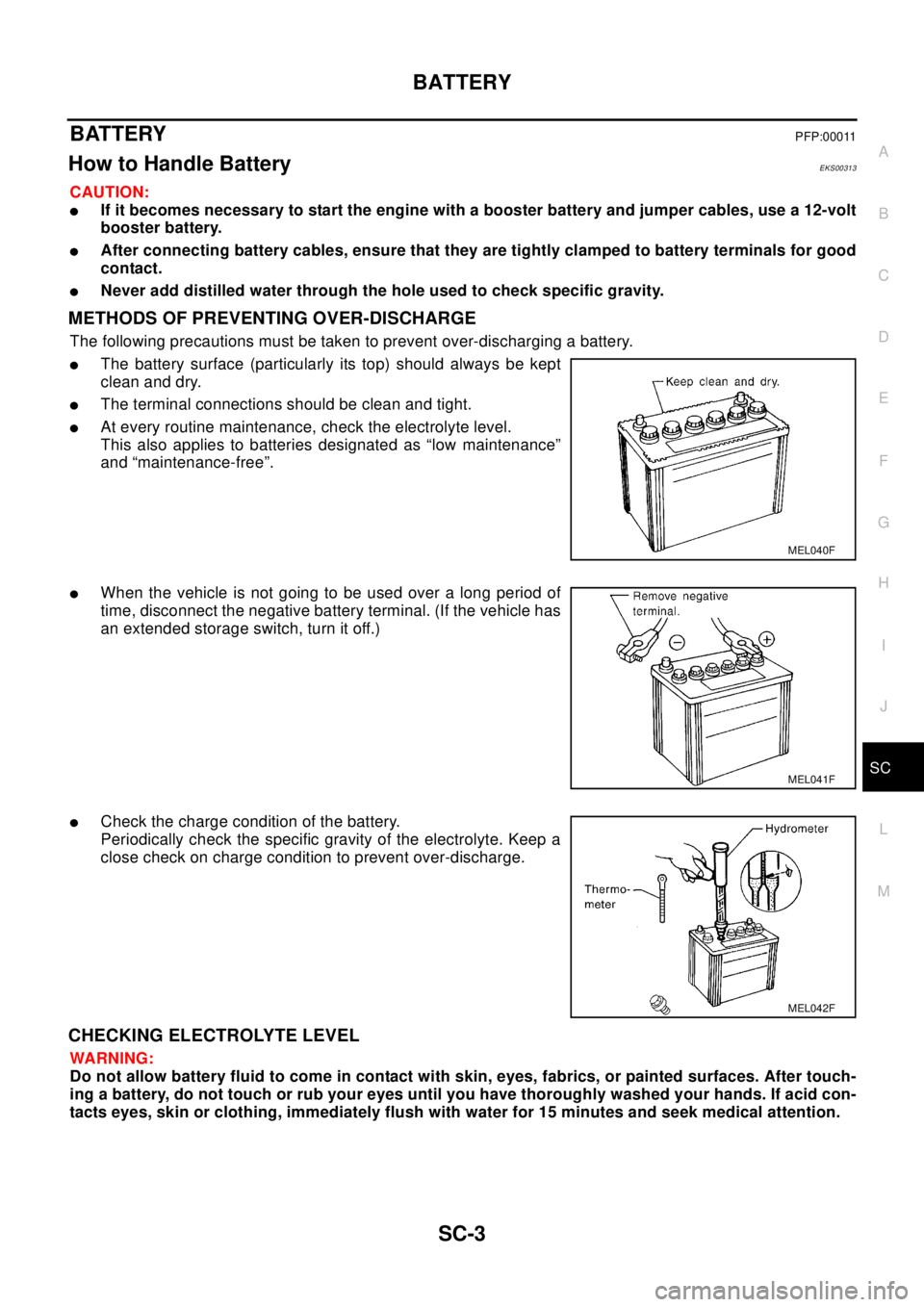
lThe battery surface (particularly its top) should always be kept
clean and dry.
lThe terminal connections should be clean and tight.
lAt every routine maintenance, check the electrolyte level.
This also applies to batteries designated as “low maintenance”
and “maintenance-free”.
lWhen the vehicle is not going to be used over a long period of
time, disconnect the negative battery terminal. (If the vehicle has
an extended storage switch, turn it off.)
lCheck the charge condition of the battery.
Periodically check the specific gravity of the electrolyte. Keep a
close check on charge condition to prevent over-discharge.
CHECKING ELECTROLYTE LEVEL
WA RN ING:
Do not allow battery fluid to come in contact with skin, eyes, fabrics, or painted surfaces. After touch-
ing a battery, do not touch or rub your eyes until you have thoroughly washed your hands. If acid con-
tacts eyes, skin or clothing, immediately flush with water for 15 minutes and seek medical attention.
MEL040F
MEL041F
MEL042F
Page 2886 of 3066
SC-14
CHARGING SYSTEM
Trouble Diagnoses
EKS00319
Before conducting an alternator test, make sure that the battery is fully charged. A 30-volt voltmeter and suit-
able test probes are necessary for the test. The alternator can be checked easily by referring to the Inspection
Table.
lBefore starting, inspect the fusible link.
lUse fully charged battery.
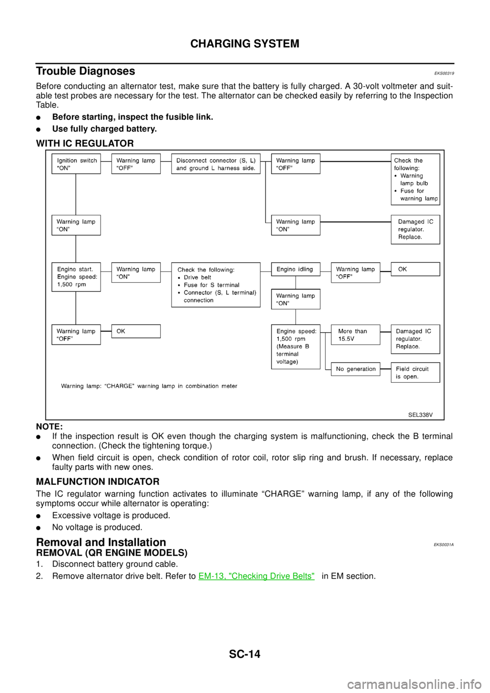
WITH IC REGULATOR
NOTE:
lIf the inspection result is OK even though the charging system is malfunctioning, check the B terminal
connection. (Check the tightening torque.)
lWhen field circuit is open, check condition of rotor coil, rotor slip ring and brush. If necessary, replace
faulty parts with new ones.
MALFUNCTION INDICATOR
The IC regulator warning function activates to illuminate “CHARGE” warning lamp, if any of the following
symptoms occur while alternator is operating:
lExcessive voltage is produced.
lNo voltage is produced.
Removal and InstallationEKS0031A
REMOVAL (QR ENGINE MODELS)
1. Disconnect battery ground cable.
2. Remove alternator drive belt. Refer toEM-13, "
Checking Drive Belts"in EM section.
SEL338V
Page 2887 of 3066
CHARGING SYSTEM
SC-15
C
D
E
F
G
H
I
J
L
MA
B
SC
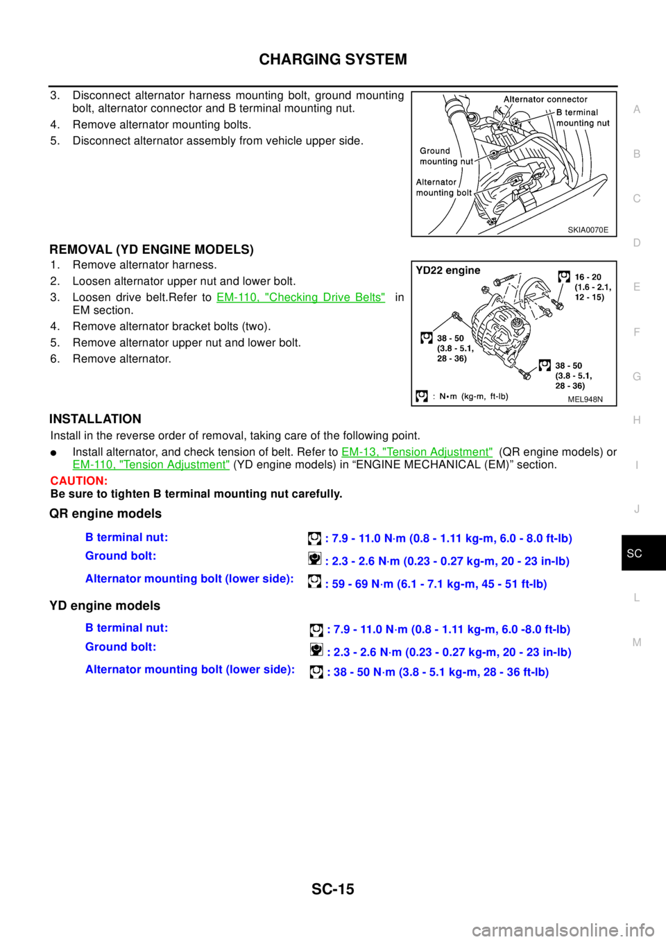
3. Disconnect alternator harness mounting bolt, ground mounting
bolt, alternator connector and B terminal mounting nut.
4. Remove alternator mounting bolts.
5. Disconnect alternator assembly from vehicle upper side.
REMOVAL (YD ENGINE MODELS)
1. Remove alternator harness.
2. Loosen alternator upper nut and lower bolt.
3. Loosen drive belt.Refer toEM-110, "
Checking Drive Belts"in
EM section.
4. Remove alternator bracket bolts (two).
5. Remove alternator upper nut and lower bolt.
6. Remove alternator.
INSTALLATION
Install in the reverse order of removal, taking care of the following point.
lInstall alternator, and check tension of belt. Refer toEM-13, "Tension Adjustment"(QR engine models) or
EM-110, "
Tension Adjustment"(YD engine models) in “ENGINE MECHANICAL (EM)” section.
CAUTION:
Be sure to tighten B terminal mounting nut carefully.
QR engine models
YD engine models
SKIA0070E
MEL948N
Bterminalnut:
: 7.9 - 11.0 N·m (0.8 - 1.11 kg-m, 6.0 - 8.0 ft-lb)
Ground bolt:
:2.3-2.6N·m(0.23-0.27kg-m,20-23in-lb)
Alternator mounting bolt (lower side):
: 59 - 69 N·m (6.1 - 7.1 kg-m, 45 - 51 ft-lb)
Bterminalnut:
: 7.9 - 11.0 N·m (0.8 - 1.11 kg-m, 6.0 -8.0 ft-lb)
Ground bolt:
: 2.3 - 2.6 N·m (0.23 - 0.27 kg-m, 20 - 23 in-lb)
Alternator mounting bolt (lower side):
: 38 - 50 N·m (3.8 - 5.1 kg-m, 28 - 36 ft-lb)
Page 2904 of 3066
SC-32
STARTING SYSTEM
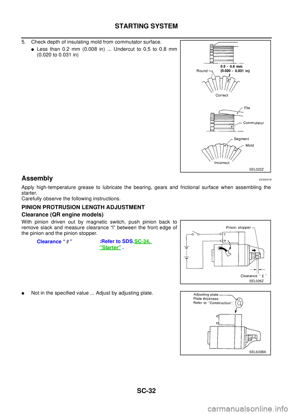
5. Check depth of insulating mold from commutator surface.
lLess than 0.2 mm (0.008 in) ... Undercut to 0.5 to 0.8 mm
(0.020 to 0.031 in)
AssemblyEKS0031M
Apply high-temperature grease to lubricate the bearing, gears and frictional surface when assembling the
starter.
Carefully observe the following instructions.
PINION PROTRUSION LENGTH ADJUSTMENT
Clearance (QR engine models)
With pinion driven out by magnetic switch, push pinion back to
remove slack and measure clearance “l” between the front edge of
the pinion and the pinion stopper.
lNot in the specified value ... Adjust by adjusting plate.
SEL022Z
Clearance “ ”:Refer to SDS.SC-34,
"Starter".
SEL026Z
SEL633BA
Page 2978 of 3066
TF-8
TRANSFER FLUID
TRANSFER FLUID
PFP:KLD30
ReplacementEDS0004Q
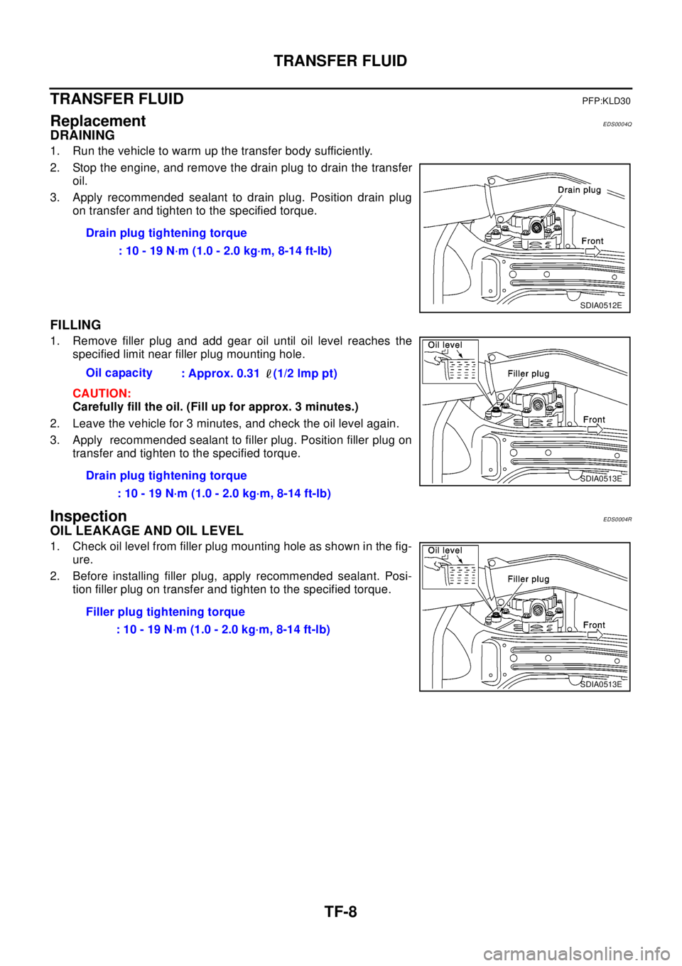
DRAINING
1. Run the vehicle to warm up the transfer body sufficiently.
2. Stop the engine, and remove the drain plug to drain the transfer
oil.
3. Apply recommended sealant to drain plug. Position drain plug
on transfer and tighten to the specified torque.
FILLING
1. Remove filler plug and add gear oil until oil level reaches the
specified limit near filler plug mounting hole.
CAUTION:
Carefully fill the oil. (Fill up for approx. 3 minutes.)
2. Leave the vehicle for 3 minutes, and check the oil level again.
3. Apply recommended sealant to filler plug. Position filler plug on
transfer and tighten to the specified torque.
InspectionEDS0004R
OIL LEAKAGE AND OIL LEVEL
1. Check oil level from filler plug mounting hole as shown in the fig-
ure.
2. Before installing filler plug, apply recommended sealant. Posi-
tion filler plug on transfer and tighten to the specified torque.Drain plug tightening torque
: 10 - 19 N·m (1.0 - 2.0 kg·m, 8-14 ft-lb)
SDIA0512E
Oil capacity
: Approx. 0.31 (1/2 lmp pt)
Drain plug tightening torque
: 10 - 19 N·m (1.0 - 2.0 kg·m, 8-14 ft-lb)
SDIA0513E
Filler plug tightening torque
:10-19N·m(1.0-2.0kg·m,8-14ft-lb)
SDIA0513E
Page 2983 of 3066
TRANSFER ASSEMBLY
TF-13
C
E
F
G
H
I
J
K
L
MA
B
TF
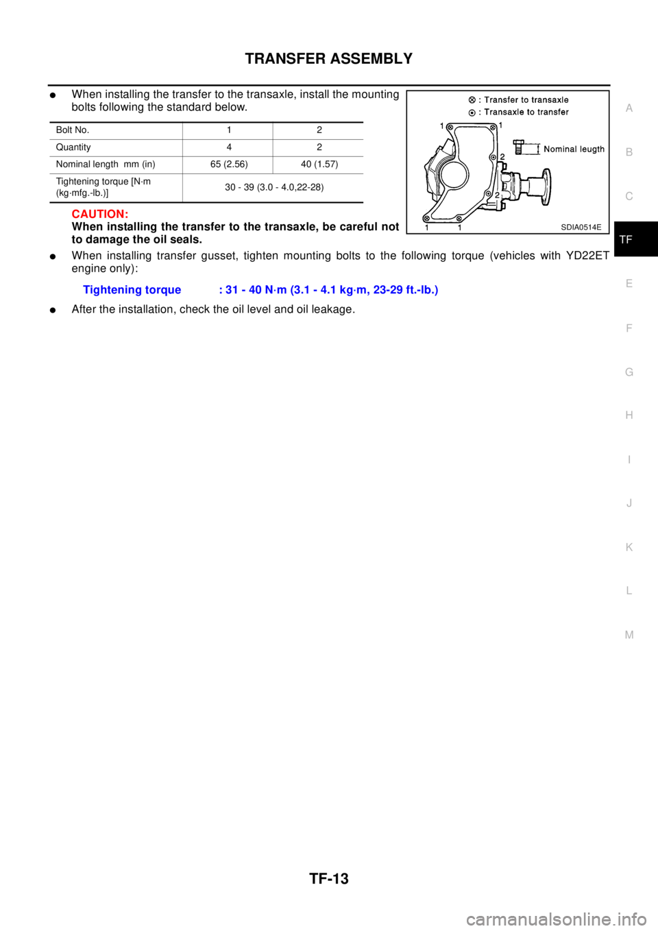
lWhen installing the transfer to the transaxle, install the mounting
bolts following the standard below.
CAUTION:
When installing the transfer to the transaxle, be careful not
to damage the oil seals.
lWhen installing transfer gusset, tighten mounting bolts to the following torque (vehicles with YD22ET
engine only):
lAfter the installation, check the oil level and oil leakage.
Bolt No. 1 2
Quantity 4 2
Nominal length mm (in) 65 (2.56) 40 (1.57)
Tightening torque [N·m
(kg·mfg.-lb.)]30 - 39 (3.0 - 4.0,22-28)
SDIA0514E
Tightening torque : 31 - 40 N·m (3.1 - 4.1 kg·m, 23-29 ft.-lb.)