2003 NISSAN X-TRAIL length
[x] Cancel search: lengthPage 2810 of 3066
RAX-14
REAR DRIVE SHAFT
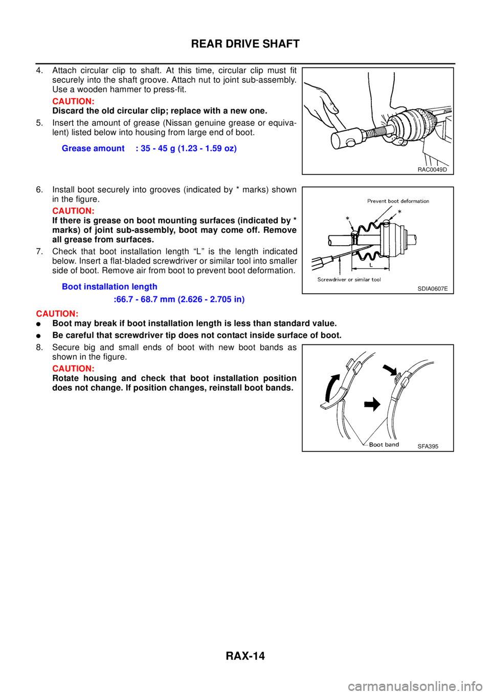
4. Attach circular clip to shaft. At this time, circular clip must fit
securely into the shaft groove. Attach nut to joint sub-assembly.
Use a wooden hammer to press-fit.
CAUTION:
Discard the old circular clip; replace with a new one.
5. Insert the amount of grease (Nissan genuine grease or equiva-
lent) listed below into housing from large end of boot.
6. Install boot securely into grooves (indicated by * marks) shown
in the figure.
CAUTION:
If there is grease on boot mounting surfaces (indicated by *
marks) of joint sub-assembly, boot may come off. Remove
all grease from surfaces.
7. Check that boot installation length “L” is the length indicated
below. Insert a flat-bladed screwdriver or similar tool into smaller
side of boot. Remove air from boot to prevent boot deformation.
CAUTION:
lBoot may break if boot installation length is less than standard value.
lBe careful that screwdriver tip does not contact inside surface of boot.
8. Secure big and small ends of boot with new boot bands as
shown in the figure.
CAUTION:
Rotate housing and check that boot installation position
does not change. If position changes, reinstall boot bands.Grease amount : 35 - 45 g (1.23 - 1.59 oz)
RAC0049D
Boot installation length
:66.7 - 68.7 mm (2.626 - 2.705 in)SDIA0607E
SFA395
Page 2811 of 3066
SERVICE DATA AND SPECIFICATIONS (SDS)
RAX-15
C
E
F
G
H
I
J
K
L
MA
B
RAX
SERVICE DATA AND SPECIFICATIONS (SDS)PFP:00030
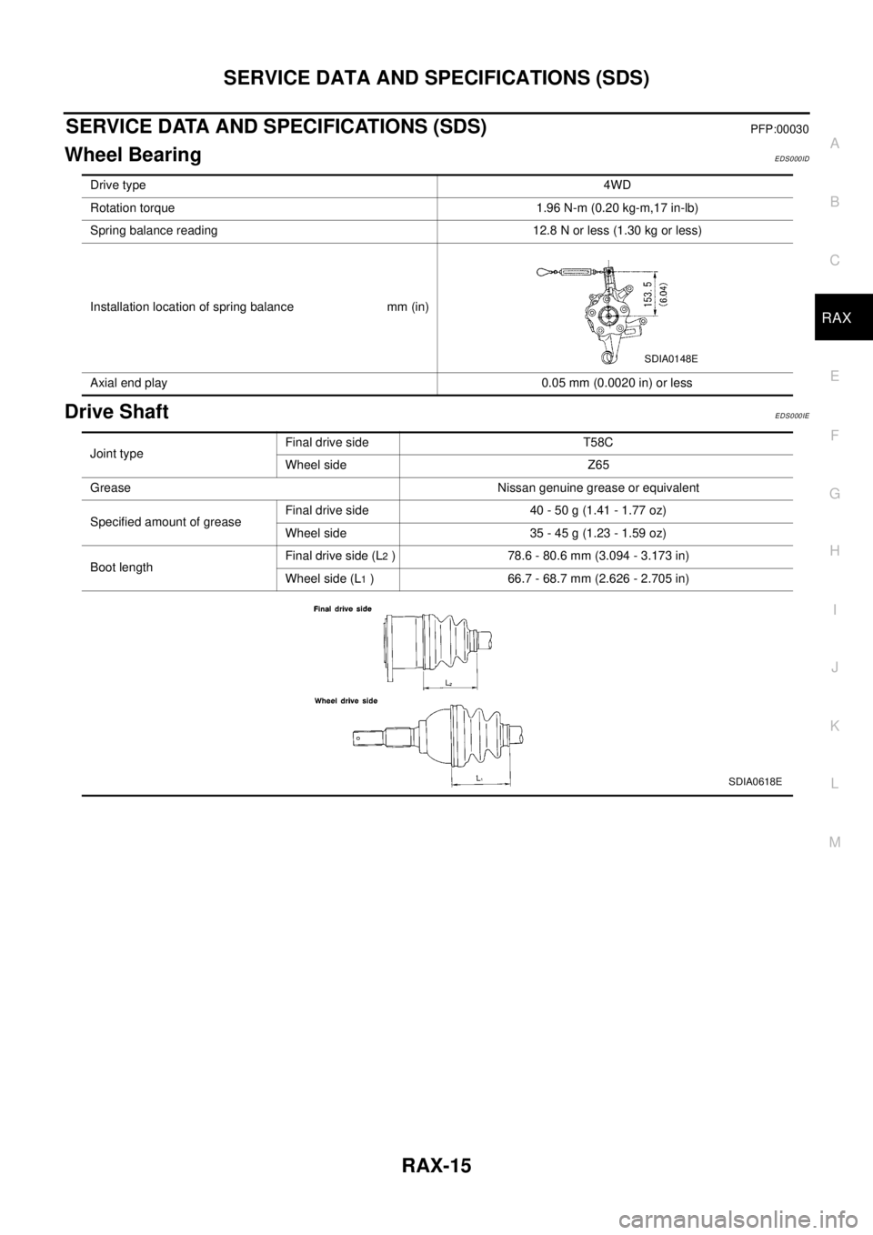
Wheel BearingEDS000ID
Drive ShaftEDS000IE
Drive type4WD
Rotation torque 1.96 N-m (0.20 kg-m,17 in-lb)
Spring balance reading 12.8 N or less (1.30 kg or less)
Installation location of spring balance mm (in)
Axial end play 0.05 mm (0.0020 in) or less
SDIA0148E
Joint typeFinal drive side T58C
Wheel side Z65
Grease Nissan genuine grease or equivalent
SpecifiedamountofgreaseFinal drive side 40 - 50 g (1.41 - 1.77 oz)
Wheelside 35-45g(1.23-1.59oz)
Boot lengthFinal drive side (L
2) 78.6 - 80.6 mm (3.094 - 3.173 in)
Wheel side (L
1) 66.7 - 68.7 mm (2.626 - 2.705 in)
SDIA0618E
Page 2873 of 3066
SC-1
STARTING & CHARGING SYSTEM
K ELECTRICAL
CONTENTS
C
D
E
F
G
H
I
J
L
M
SECTION
A
B
SC
STARTING & CHARGING SYSTEM
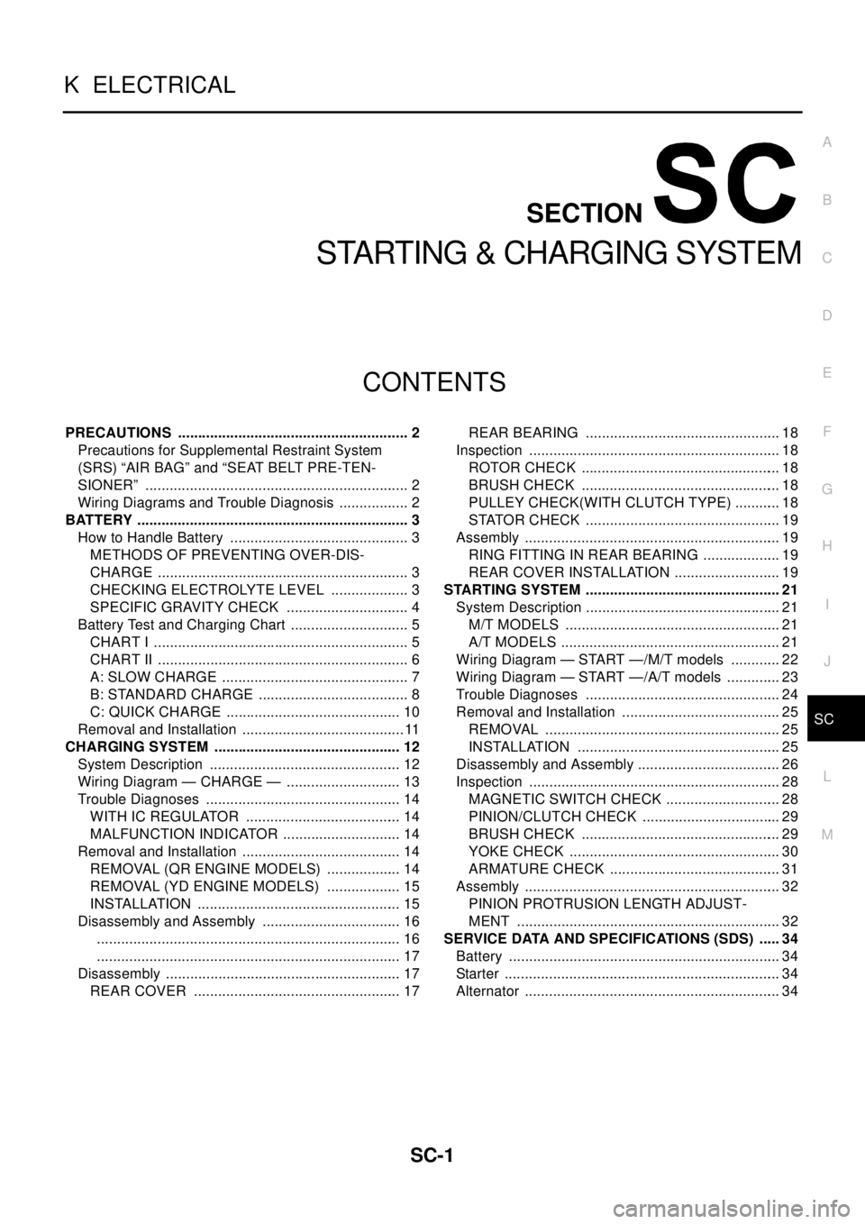
PRECAUTIONS .......................................................... 2
Precautions for Supplemental Restraint System
(SRS) “AIR BAG” and “SEAT BELT PRE-TEN-
SIONER” .................................................................. 2
Wiring Diagrams and Trouble Diagnosis .................. 2
BATTERY .................................................................... 3
How to Handle Battery ............................................. 3
METHODS OF PREVENTING OVER-DIS-
CHARGE ............................................................... 3
CHECKING ELECTROLYTE LEVEL .................... 3
SPECIFIC GRAVITY CHECK ............................... 4
Battery Test and Charging Chart .............................. 5
CHART I ................................................................ 5
CHART II ............................................................... 6
A: SLOW CHARGE ............................................... 7
B: STANDARD CHARGE ...................................... 8
C: QUICK CHARGE ............................................ 10
Removal and Installation .........................................11
CHARGING SYSTEM ............................................... 12
System Description ................................................ 12
Wiring Diagram — CHARGE — ............................. 13
Trouble Diagnoses ................................................. 14
WITH IC REGULATOR ....................................... 14
MALFUNCTION INDICATOR .............................. 14
Removal and Installation ........................................ 14
REMOVAL (QR ENGINE MODELS) ................... 14
REMOVAL (YD ENGINE MODELS) ................... 15
INSTALLATION ................................................... 15
Disassembly and Assembly ................................... 16
............................................................................ 16
............................................................................ 17
Disassembly ........................................................... 17
REAR COVER .................................................... 17REAR BEARING ................................................. 18
Inspection ............................................................... 18
ROTOR CHECK .................................................. 18
BRUSH CHECK .................................................. 18
PULLEY CHECK(WITH CLUTCH TYPE) ............ 18
STATOR CHECK ................................................. 19
Assembly ................................................................ 19
RING FITTING IN REAR BEARING .................... 19
REAR COVER INSTALLATION ........................... 19
STARTING SYSTEM ................................................. 21
System Description ................................................. 21
M/T MODELS ...................................................... 21
A/T MODELS ....................................................... 21
Wiring Diagram — START —/M/T models ............. 22
Wiring Diagram — START —/A/T models .............. 23
Trouble Diagnoses ................................................. 24
Removal and Installation ........................................ 25
REMOVAL ........................................................... 25
INSTALLATION ................................................... 25
Disassembly and Assembly .................................... 26
Inspection ............................................................... 28
MAGNETIC SWITCH CHECK ............................. 28
PINION/CLUTCH CHECK ................................... 29
BRUSH CHECK .................................................. 29
YOKE CHECK ..................................................... 30
ARMATURE CHECK ........................................... 31
Assembly ................................................................ 32
PINION PROTRUSION LENGTH ADJUST-
MENT .................................................................. 32
SERVICE DATA AND SPECIFICATIONS (SDS) ...... 34
Battery .................................................................... 34
Starter ..................................................................... 34
Alternator ................................................................ 34
Page 2901 of 3066
STARTING SYSTEM
SC-29
C
D
E
F
G
H
I
J
L
MA
B
SC
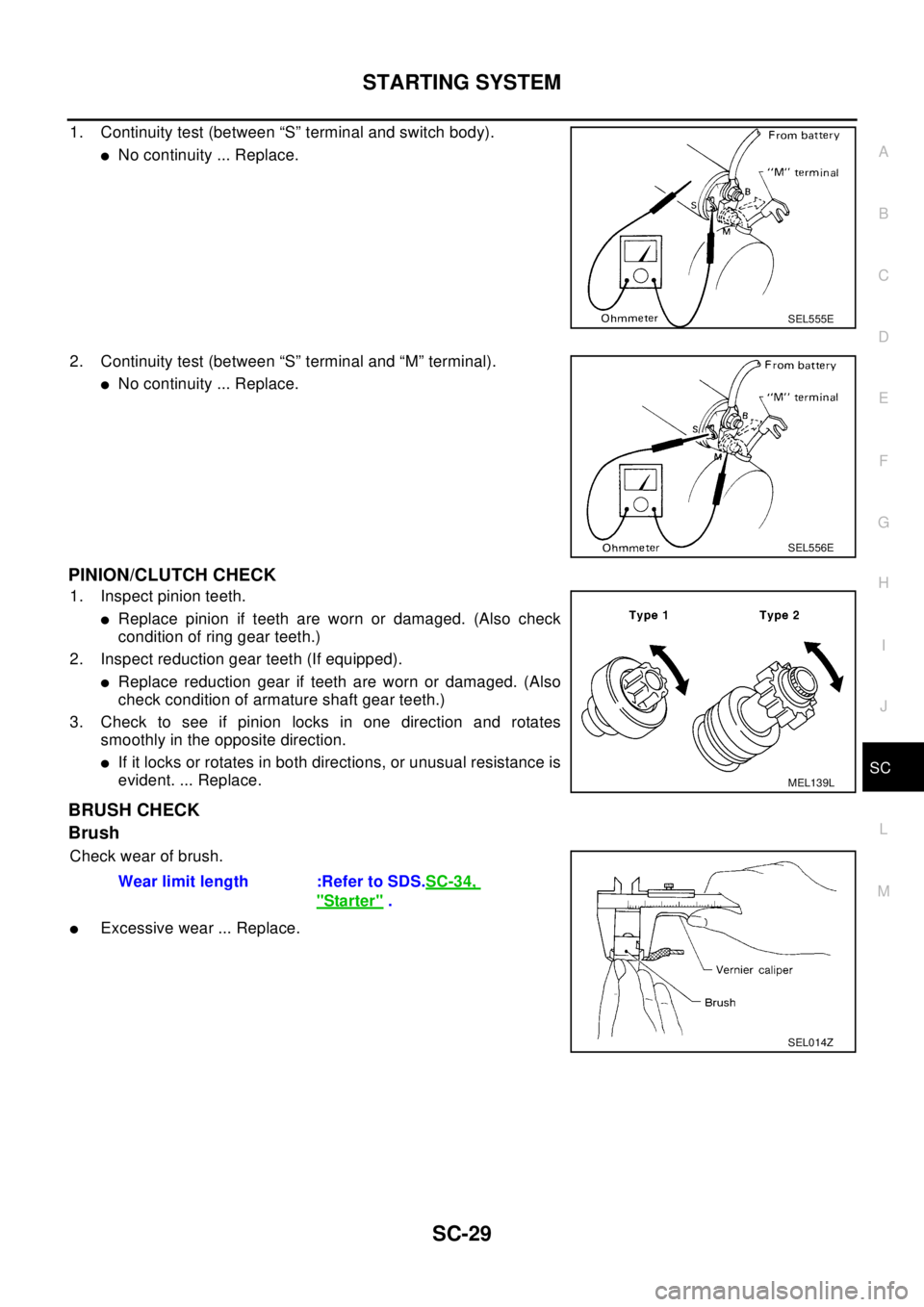
1. Continuity test (between “S” terminal and switch body).
lNo continuity ... Replace.
2. Continuity test (between “S” terminal and “M” terminal).
lNo continuity ... Replace.
PINION/CLUTCH CHECK
1. Inspect pinion teeth.
lReplace pinion if teeth are worn or damaged. (Also check
condition of ring gear teeth.)
2. Inspect reduction gear teeth (If equipped).
lReplace reduction gear if teeth are worn or damaged. (Also
check condition of armature shaft gear teeth.)
3. Check to see if pinion locks in one direction and rotates
smoothly in the opposite direction.
lIf it locks or rotates in both directions, or unusual resistance is
evident. ... Replace.
BRUSH CHECK
Brush
Check wear of brush.
lExcessive wear ... Replace.
SEL555E
SEL556E
MEL139L
Wear limit length :Refer to SDS.SC-34,
"Starter".
SEL014Z
Page 2904 of 3066
SC-32
STARTING SYSTEM
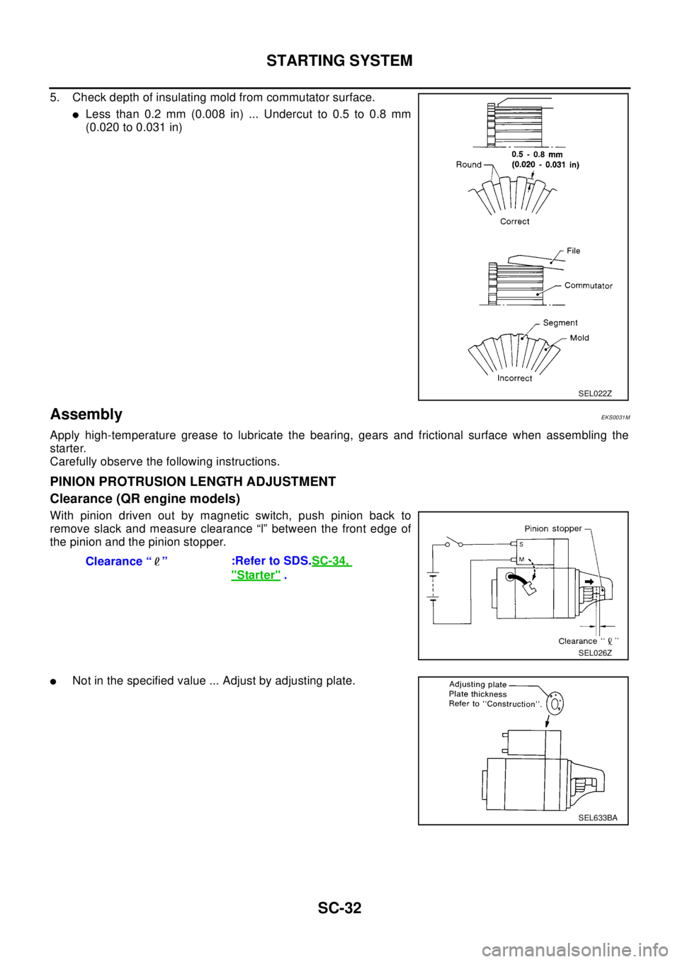
5. Check depth of insulating mold from commutator surface.
lLess than 0.2 mm (0.008 in) ... Undercut to 0.5 to 0.8 mm
(0.020 to 0.031 in)
AssemblyEKS0031M
Apply high-temperature grease to lubricate the bearing, gears and frictional surface when assembling the
starter.
Carefully observe the following instructions.
PINION PROTRUSION LENGTH ADJUSTMENT
Clearance (QR engine models)
With pinion driven out by magnetic switch, push pinion back to
remove slack and measure clearance “l” between the front edge of
the pinion and the pinion stopper.
lNot in the specified value ... Adjust by adjusting plate.
SEL022Z
Clearance “ ”:Refer to SDS.SC-34,
"Starter".
SEL026Z
SEL633BA
Page 2906 of 3066

SC-34
SERVICE DATA AND SPECIFICATIONS (SDS)
SERVICE DATA AND SPECIFICATIONS (SDS)
PFP:00030
BatteryEKS0031Q
StarterEKS0031R
AlternatorEKS0031S
Applied modelQR20 engine
YD22 engine
Standard Option
Type 55D23L 80D26L 110D26L
Capacity V-AH 12-48 12-55 12-70
Ty p eS114-844 M0T87081 M8T71471
HITACHI make MITSUBISHI make
Reduction
Applied model QR20 engine YD22 engine
System voltage V12
No-loadTerminal voltage V 11.0
Current A Less than 90 Less than 90 Less than 145
Revolution rpm More than 2,700 More than 2,500 More than 3,300
Minimum diameter of commutator mm (in) 28.0 (1.102) 28.8 (1.134) 31.4 (1.236)
Minimum length of brush mm (in) 10.5 (0.413) 7.0 (0.276) 11.0 (0.433)
Brush spring tension N (kg, lb) 16.2(1.65, 3.64)15.0 - 20.4(1.5 - 2.1, 3.4
-4.6)26.7 - 36.1(2.7 - 3.7, 6.0
-8.2)
Clearance between bearing metal and armature
shaft mm (in)Less than 0.2 (0.008) —
Clearance “l” between pinion front edge and pinion
stopper mm (in)0.3 - 2.5 (0.012 - 0.098) 0.5 - 2.0(0.020 - 0.079) —
Movement “l” in height of pinion assembly mm (in) — 0.5 - 2.0(0.020 - 0.079)
Ty p eLR1110-713 A3TB0771
HITACHI make MITSUBISHI make
Applied model QR20 engine YD22 engine
Nominal rating V-A 12-110 12-90
Ground polarityNegative
Minimum revolutions under no-load (When 13.5V is
applied) rpmLess than 1,100 Less than 1,300
Hot output current (When 13.5V is applied) A/rpmMore than35/1,300
More than91/2,500
More than110/5,000More than29/1,300
More than76/2,500
More than88/5,000
Regulated output voltage V 14.1 - 14.7
Minimum length of brush mm (in) More than 6.0 (0.236) More than 5.0 (0.197)
Brush spring pressure N (g, oz) 1.0 - 3.43 (102 - 350, 3.60 - 12.34) 4.8 - 6.0 (490 - 610, 17.28 - 21.51)
Slip ring minimum diameter mm (in) More than 26.0 (1.024) More than 22.1 (0.870)
Rotor coil resistance at 20°(68°F)W2.31 2.1 - 2.5
Page 2983 of 3066
TRANSFER ASSEMBLY
TF-13
C
E
F
G
H
I
J
K
L
MA
B
TF
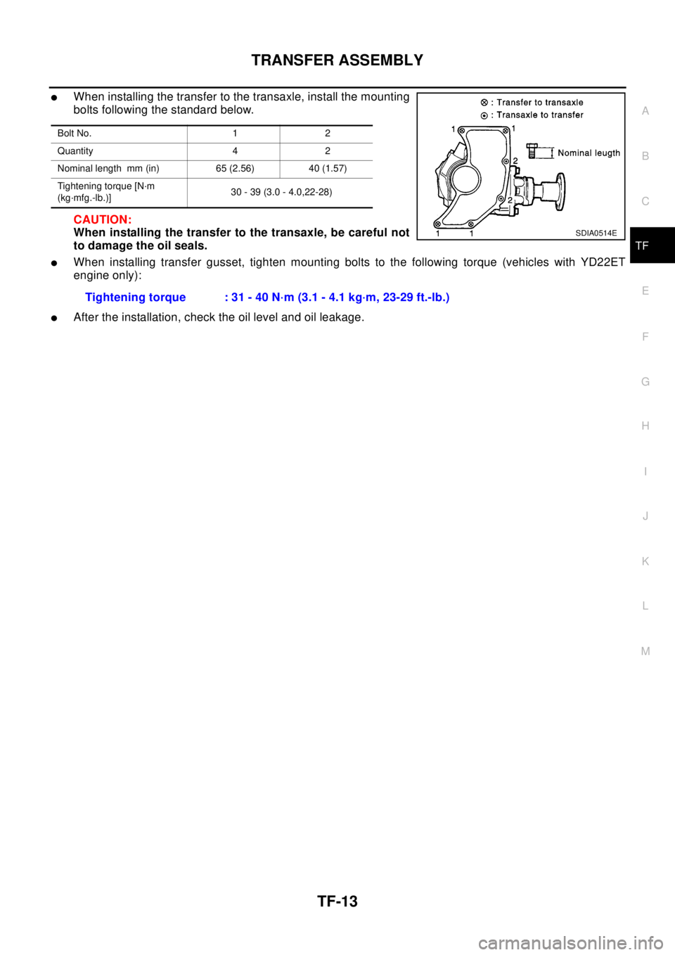
lWhen installing the transfer to the transaxle, install the mounting
bolts following the standard below.
CAUTION:
When installing the transfer to the transaxle, be careful not
to damage the oil seals.
lWhen installing transfer gusset, tighten mounting bolts to the following torque (vehicles with YD22ET
engine only):
lAfter the installation, check the oil level and oil leakage.
Bolt No. 1 2
Quantity 4 2
Nominal length mm (in) 65 (2.56) 40 (1.57)
Tightening torque [N·m
(kg·mfg.-lb.)]30 - 39 (3.0 - 4.0,22-28)
SDIA0514E
Tightening torque : 31 - 40 N·m (3.1 - 4.1 kg·m, 23-29 ft.-lb.)