Page 2153 of 3066
![NISSAN X-TRAIL 2003 Electronic Repair Manual CYLINDER HEAD
EM-183
[YD22DDTi]
C
D
E
F
G
H
I
J
K
L
MA
EM
8. Use a depth gauge to measure the distance between the mount-
ing surface of the cylinder head spring seat and the valve stem
end. If the di NISSAN X-TRAIL 2003 Electronic Repair Manual CYLINDER HEAD
EM-183
[YD22DDTi]
C
D
E
F
G
H
I
J
K
L
MA
EM
8. Use a depth gauge to measure the distance between the mount-
ing surface of the cylinder head spring seat and the valve stem
end. If the di](/manual-img/5/57402/w960_57402-2152.png)
CYLINDER HEAD
EM-183
[YD22DDTi]
C
D
E
F
G
H
I
J
K
L
MA
EM
8. Use a depth gauge to measure the distance between the mount-
ing surface of the cylinder head spring seat and the valve stem
end. If the distance is shorter than specified, repeat step 5
above to adjust it. If it is longer, replace the valve seat with a
new one.
Valve Spring Sequences
Position a straightedge to valve spring, turn the spring, and measure
the maximum clearance value between top surface of spring and the
straightedge.
Valve Spring Dimensions and Valve Spring Pressure Load
Using valve spring tester, check the following.Valve seat resurface limit “L”:
Intake : 36.53 - 36.98 mm (1.4382 - 1.4559 in)
Exhaust : 36.53 - 37.01 mm (1.4382 - 1.4571 in)
JEM253G
Limit : 1.9 mm (0.075 in)
PBIC0080E
Free length : 43.7 mm (1.720 in)
Installation height : 32.82 mm (1.2921 in)
Installation load : 184 - 208 N
(18.77 - 21.22 kg, 41.4 - 46.8 lb)
Height during
valve open: 24.82 mm (0.9772 in)
Loadwithvalve
open: 320 - 360 N
(32.65 - 36.73 kg, 71.9 - 80.9 lb)
SEM113
Page 2181 of 3066
SERVICE DATA AND SPECIFICATIONS (SDS)
EM-211
[YD22DDTi]
C
D
E
F
G
H
I
J
K
L
MA
EM
CYLINDER HEAD
Unit: mm (in)
VA LV E
Valve
Unit: mm (in)
Valve Clearance
Unit: mm (in)
*1: Approximately 20°C(68°F)
*2: Approximately 80°C(176°F) Item Standard Limit
Head surface distortion Less than 0.03 (0.0012) 0.04 (0.0016)
JEM204G
Valve head diameter “D”Intake 28.0 - 28.3 (1.102 - 1.114)
Exhaust 26.0 - 26.3 (1.024 - 1.035)
Valve length “L”Intake 106.72 (4.2016)
Exhaust 106.36 (4.1874)
Valve stem diameter “d”Intake 5.965 - 5.980 (0.2348 - 0.2354)
Exhaust 5.945 - 5.960 (0.2341 - 0.2346)
Valve seat angle “a”Intake
45°15¢-45°45¢
Exhaust
Valvemargin“T”Intake 1.38 (0.0543)
Exhaust 1.48 (0.0583)
Valve margin “T” limitMore than 1.0 (0.039)
Valve stem end surface grinding limit Less than 0.2 (0.008)
SEM188
Item Cold*1 Hot*2 (referance data)
Intake 0.24 - 0.32 (0.0094 - 0.0126) 0.274 - 0.386 (0.011 - 0.015)
Exhaust 0.26 - 0.34 (0.0102 - 0.0134) 0.308 - 0.432 (0.012 - 0.017)
Page 2183 of 3066
![NISSAN X-TRAIL 2003 Electronic Repair Manual SERVICE DATA AND SPECIFICATIONS (SDS)
EM-213
[YD22DDTi]
C
D
E
F
G
H
I
J
K
L
MA
EM
Valve Spring
Valve Lifter
Unit: mm (in)
Valve Guide
Unit: mm (in) Free height mm (in) 43.7 (1.720)
Pressure N (kg, lb) NISSAN X-TRAIL 2003 Electronic Repair Manual SERVICE DATA AND SPECIFICATIONS (SDS)
EM-213
[YD22DDTi]
C
D
E
F
G
H
I
J
K
L
MA
EM
Valve Spring
Valve Lifter
Unit: mm (in)
Valve Guide
Unit: mm (in) Free height mm (in) 43.7 (1.720)
Pressure N (kg, lb)](/manual-img/5/57402/w960_57402-2182.png)
SERVICE DATA AND SPECIFICATIONS (SDS)
EM-213
[YD22DDTi]
C
D
E
F
G
H
I
J
K
L
MA
EM
Valve Spring
Valve Lifter
Unit: mm (in)
Valve Guide
Unit: mm (in) Free height mm (in) 43.7 (1.720)
Pressure N (kg, lb) at height mm (in) 184 - 208 (18.77 - 21.22, 41.4 - 46.8) at 32.82 (1.2921)
Out-of-square mm (in) 1.9 (0.075)
Heigh during valve open mm (in) 24.82 (0.9772)
Load with valve open N (kg, ib) 320 - 360 (32.65 - 36.73, 71.9 - 80.9)
Item Standard
Valve lifter outer diameter 29.960 - 29.975 (1.1795 - 1.1801)
Lifter guide inner diameter 30.000 - 30.021 (1.1811 - 1.1819)
Clearance between lifter and lifter guide 0.025 - 0.061 (0.0010 - 0.0024)
Item Standard Service
Valve guide Outer diameter 10.023 - 10.034 (0.3946 - 0.3950) 10.223 - 10.234 (0.4025 - 0.4029)
Valve guide Inner diameter (Finished size) 6.000 - 6.018 (0.2362 - 0.2369)
Cylinder head valve guide hole diameter 9.975 - 9.996 (0.3927 - 0.3935) 10.175 - 10.196 (0.4006 - 0.4014)
Interference fit of valve guide 0.027 - 0.059 (0.0011 - 0.0023)
Item Standard Limit
Stem to guide clearanceIntake 0.020 - 0.053 (0.0008 - 0.0021) 0.08 (0.0031)
Exhaust 0.040 - 0.073 (0.0016 - 0.0029) 0.1 (0.004)
Valve deflection limit 0.15 (0.0059)
Projection length 10.4 - 10.6 (0.4094 - 0.4173)
JEM156G
Page 2211 of 3066

FRONT DRIVE SHAFT
FAX-15
C
E
F
G
H
I
J
K
L
MA
B
FA X
Joint Assembly (Wheel Side)
CAUTION:
Joint assembly cannot be disassembled. Do not attempt to disassemble it.
ASSEMBLY
Transaxle Side
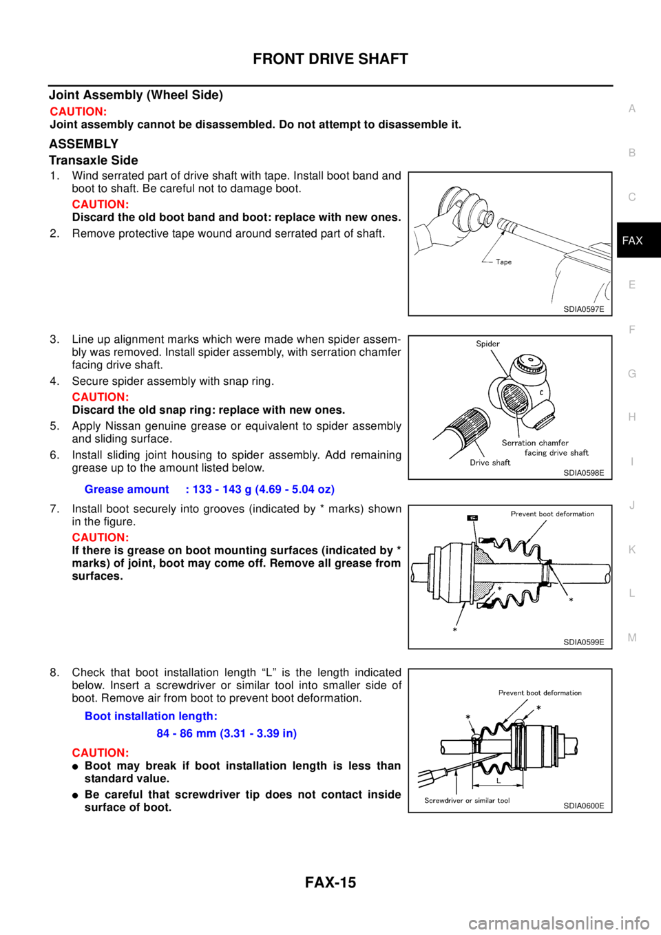
1. Wind serrated part of drive shaft with tape. Install boot band and
boot to shaft. Be careful not to damage boot.
CAUTION:
Discard the old boot band and boot: replace with new ones.
2. Remove protective tape wound around serrated part of shaft.
3. Line up alignment marks which were made when spider assem-
bly was removed. Install spider assembly, with serration chamfer
facing drive shaft.
4. Secure spider assembly with snap ring.
CAUTION:
Discard the old snap ring: replace with new ones.
5. Apply Nissan genuine grease or equivalent to spider assembly
and sliding surface.
6. Install sliding joint housing to spider assembly. Add remaining
grease up to the amount listed below.
7. Install boot securely into grooves (indicated by * marks) shown
in the figure.
CAUTION:
If there is grease on boot mounting surfaces (indicated by *
marks) of joint, boot may come off. Remove all grease from
surfaces.
8. Check that boot installation length “L” is the length indicated
below. Insert a screwdriver or similar tool into smaller side of
boot. Remove air from boot to prevent boot deformation.
CAUTION:
lBoot may break if boot installation length is less than
standard value.
lBe careful that screwdriver tip does not contact inside
surface of boot.
SDIA0597E
Grease amount : 133 - 143 g (4.69 - 5.04 oz)
SDIA0598E
SDIA0599E
Boot installation length:
84 - 86 mm (3.31 - 3.39 in)
SDIA0600E
Page 2213 of 3066

SERVICE DATA AND SPECIFICATIONS (SDS)
FAX-17
C
E
F
G
H
I
J
K
L
MA
B
FA X
SERVICE DATA AND SPECIFICATIONS (SDS)PFP:00030
Wheel BearingEDS000IG
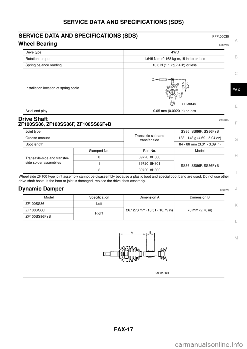
Drive ShaftEDS000IH
ZF100SS86, ZF100SS86F, ZF100SS86F+B
Wheel side ZF100 type joint assembly cannot be disassembly because a plastic boot and special boot band are used. Do not use other
drive shaft boots. If the boot or joint is damaged, replace the drive shaft assembly.
Dynamic DamperEDS0 00 II
Drive type4WD
Rotation torque 1.645 N·m (0.168 kg-m,15 in-lb) or less
Spring balance reading 10.6 N (1.1 kg,2.4 lb) or less
Installation location of spring scale
Axial end play 0.05 mm (0.0020 in) or less
SDIA0148E
Joint type
Transaxle side and
transfer sideSS86, SS86F, SS86F+B
Grease amount133-143g(4.69-5.04oz)
Boot length84 - 86 mm (3.31 - 3.39 in)
Transaxle-side and transfer-
side spider assembliesStamped No. Part No. Model
0 39720 8H300
SS86, SS86F, SS86F+B 1 39720 8H301
2 39720 8H302
Model Specification Dimension A Dimension B
ZF100SS86 Left
267 273 mm (10.51 - 10.75 in) 70 mm (2.76 in) ZF100SS86F
Right
ZF100SS86F+B
FAC0156D
Page 2225 of 3066
![NISSAN X-TRAIL 2003 Electronic Repair Manual FL-10
[QR20DE]
FUEL TANK
8. Remove propeller shaft. Refer toPR-3, "Removal and Installation".
9. Using a transmission jack, support the bottom of the rear final
drive.
10. Remove the mounting nuts on NISSAN X-TRAIL 2003 Electronic Repair Manual FL-10
[QR20DE]
FUEL TANK
8. Remove propeller shaft. Refer toPR-3, "Removal and Installation".
9. Using a transmission jack, support the bottom of the rear final
drive.
10. Remove the mounting nuts on](/manual-img/5/57402/w960_57402-2224.png)
FL-10
[QR20DE]
FUEL TANK
8. Remove propeller shaft. Refer toPR-3, "Removal and Installation".
9. Using a transmission jack, support the bottom of the rear final
drive.
10. Remove the mounting nuts on the rear suspension member, and
lower the transmission jack carefully until just before the rear
suspension member is removed from the stud bolts on the vehi-
cle.
11. Disconnect fuel filler hose, EVAP hose and vent hose at fuel
tank side.
12. For disconnection procedure of the quick connector on the
evaporator hose, Refer toFL-4, "
FUEL LEVEL SENSOR UNIT,
FUEL FILTER AND FUEL PUMP ASSEMBLY".
13. Remove fuel tank protector.
14. Remove fuel tank band mounting bolts while supporting fuel
tank.
15. Remove fuel tank.
INSTALLATION
Install in the reverse order of removal paying attention to the following.
lSurely clamp fuel hoses and insert hose to the length below.
lBe sure hose clamp is not placed on swelled area of fuel tube.
lTighten fuel hose clamp so that the distance between its lugs becomes to the following.
lPush the mounting band pin to the vehicle side securely.
lBefore fixing the fuel tank, temporarily install the filler tube.
CAUTION:
Use genuine fuel filler tube mounting bolts or equivalent. Make sure to tighten them to the speci-
fied torque.
lTo connect the quick connector, refer toFL-4, "FUEL LEVEL SENSOR UNIT, FUEL FILTER AND FUEL
PUMP ASSEMBLY".
KBIA0285E
KBIA0286E
KBIA0290E
Fuel filler hose : 35mm (1.38 in)
The other hoses : 25mm (0.98 in)
Fuel tank side : 5 - 9 mm (0.20 - 0.35 in)
Fuel filler tube side : 7 - 11 mm (0.28 - 0.43 in)
Page 2237 of 3066
![NISSAN X-TRAIL 2003 Electronic Repair Manual FL-22
[YD22DDTi]
FUEL TANK
10. Using a transmission jack, support the bottom of the rear final
drive.
11. Remove the mounting nuts on the rear suspension member, and
lower the transmission jack carefu NISSAN X-TRAIL 2003 Electronic Repair Manual FL-22
[YD22DDTi]
FUEL TANK
10. Using a transmission jack, support the bottom of the rear final
drive.
11. Remove the mounting nuts on the rear suspension member, and
lower the transmission jack carefu](/manual-img/5/57402/w960_57402-2236.png)
FL-22
[YD22DDTi]
FUEL TANK
10. Using a transmission jack, support the bottom of the rear final
drive.
11. Remove the mounting nuts on the rear suspension member, and
lower the transmission jack carefully until just before the rear
suspension member is removed from the stud bolts on the vehi-
cle.
12. Disconnect fuel filler hose, EVAP hose and vent hose at fuel
tank side.
For disconnection procedure of the quick connector. Refer to
FL-17, "
FUEL LEVEL SENSOR UNIT".
13. Remove fuel tank protector.
14. Remove fuel tank band mounting bolts while supporting fuel
tank.
15. Remove fuel tank.
INSTALLATION
lInstall in the reverse order of removal paying attention to the following.
lSurely clamp fuel hoses and insert hose to the length below.
lBe sure hose clamp is not positioned on swelled area of fuel tube.
lTighten fuel hose clamp so that the distance between its lugs becomes to the following.
lPush the mounting band pin to the vehicle side securely.
lBefore fixing the fuel tank, temporarily install the fuel filler tube.
CAUTION:
Use genuine fuel filler tube mounting bolts or equivalent. Make sure to tighten them to the speci-
fied torque.
lTo connect the quick connector. Refer toFL-17, "FUEL LEVEL SENSOR UNIT".
Inspection After InstallationEBS00BL4
Run engine and check for fuel leaks at connections.
KBIA0285E
KBIA0286E
KBIA0290E
Fuel filler hose : 35 mm (1.38 in)
The other hose : 25 mm (0.98 in)
Fuel tank side : 5 - 9 mm (0.20 - 0.35 in)
Fuel filler tube side : 7 - 11 mm (0.28 - 0.43 in)
Page 2259 of 3066

GI-6
PRECAUTIONS
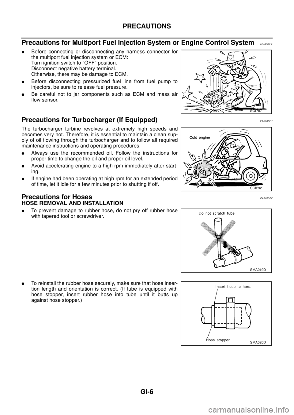
Precautions for Multiport Fuel Injection System or Engine Control System
EAS000FT
lBefore connecting or disconnecting any harness connector for
the multiport fuel injection system or ECM:
Turn ignition switch to “OFF” position.
Disconnect negative battery terminal.
Otherwise, there may be damage to ECM.
lBefore disconnecting pressurized fuel line from fuel pump to
injectors, be sure to release fuel pressure.
lBe careful not to jar components such as ECM and mass air
flow sensor.
Precautions for Turbocharger (If Equipped)EAS000FU
The turbocharger turbine revolves at extremely high speeds and
becomes very hot. Therefore, it is essential to maintain a clean sup-
ply of oil flowing through the turbocharger and to follow all required
maintenance instructions and operating procedures.
lAlways use the recommended oil. Follow the instructions for
proper time to change the oil and proper oil level.
lAvoid accelerating engine to a high rpm immediately after start-
ing.
lIf engine had been operating at high rpm for an extended period
of time, let it idle for a few minutes prior to shutting if off.
Precautions for HosesEAS000FV
HOSE REMOVAL AND INSTALLATION
lTo prevent damage to rubber hose, do not pry off rubber hose
with tapered tool or screwdriver.
lTo reinstall the rubber hose securely, make sure that hose inser-
tion length and orientation is correct. (If tube is equipped with
hose stopper, insert rubber hose into tube until it butts up
against hose stopper.)
SGI787
SGI292
SMA019D
SMA020D