2003 NISSAN X-TRAIL power steering fluid
[x] Cancel search: power steering fluidPage 2761 of 3066

PS-1
POWER STEERING SYSTEM
G STEERING
CONTENTS
C
D
E
F
H
I
J
K
L
M
SECTION
A
B
PS
POWER STEERING SYSTEM
PRECAUTIONS .......................................................... 2
Precautions for models with SRS air bag and pre-
tensioner seat belt .................................................... 2
Caution ..................................................................... 2
PREPARATION ........................................................... 3
Special Service Tools ............................................... 3
NOISE, VIBRATION, AND HARSHNESS (NVH)
TROUBLESHOOTING ................................................ 4
NVH Trouble shooting Chart .................................... 4
POWER STEERING FLUID ........................................ 5
Checking Fluid Level ................................................ 5
Checking Fluid Leak ................................................. 5
Bleeding Hydraulic System ...................................... 5
STEERING WHEEL .................................................... 6
On-Vehicle Inspection and Service .......................... 6
PLAY INSPECTION .............................................. 6
NEUTRAL POSITION INSPECTION .................... 6
STEERING TORQUE CHECK .............................. 6
STEERING ANGLE INSPECTION ........................ 6
Removal and Installation .......................................... 7
REMOVAL ............................................................. 7
INSTALLATION ..................................................... 7
STEERING COLUMN ................................................. 9
Removal and Installation .......................................... 9
REMOVAL OF LOWER JOINT AND HOLE
COVER ................................................................. 9
INSTALLATION OF LOWER JOINT AND HOLE
COVER ................................................................. 9
REMOVAL OF STEERING COLUMN ASSEM-
BLY ........................................................................ 9
INSTALLING STEERING COLUMN ASSEMBLY... 10
Disassembly and Assembly ................................... 10
DISASSEMBLY ................................................... 10
INSPECTION AFTER DISASSEMBLY. ...............11
ASSEMBLY ..........................................................11
POWER STEERING GEAR AND LINKAGE ............ 12
Removal and Installation ........................................ 12
REMOVAL ........................................................... 12
INSTALLATION ................................................... 12Components ........................................................... 14
MODEL PR24AD ................................................. 14
Disassembly and Assembly .................................... 15
DISASSEMBLY ................................................... 15
PINION GEAR ROTATION TORQUE ADJUST-
MENT .................................................................. 16
INSPECTION AFTER DISASSEMBLY ................ 16
ASSEMBLY ......................................................... 17
POWER STEERING OIL PUMP ............................... 23
On-Vehicle Inspection and Service ......................... 23
OIL PUMP PULLEY HYDRAULIC PRESSURE
INSPECTION ...................................................... 23
Removal and Installation (QR20DE engine model)... 23
REMOVAL ........................................................... 23
INSTALLATION ................................................... 23
Disassembly and Assembly(QR20DE engine
model) ..................................................................... 24
INSPECTION BEFORE DISASSEMBLY ............. 24
DISASSEMBLY ................................................... 24
INSPECTION AFTER DISASSEMBLY ................ 25
ASSEMBLY ......................................................... 25
Removal and Installation (YD22DDTi engine
model) ..................................................................... 28
Disassembly and Assembly (YD22DDTi engine
model) ..................................................................... 29
INSPECTION BEFORE DISASSEMBLY ............. 29
DISASSEMBLY ................................................... 30
INSPECTION AFTER DISASSEMBLY ................ 31
ASSEMBLY ......................................................... 31
HYDRAULIC LINE .................................................... 33
Removal and Installation ........................................ 33
SERVICE DATA AND SPECIFICATIONS (SDS) ...... 35
Wheel ..................................................................... 35
Steering Angle ........................................................ 35
Steering Column ..................................................... 35
Steering Linkage ..................................................... 35
Steering Gear ......................................................... 36
Oil Pump ................................................................. 36
Steering Fluid .......................................................... 36
Page 2762 of 3066

PS-2
PRECAUTIONS
PRECAUTIONS
PFP:00001
Precautions for models with SRS air bag and pre-tensioner seat beltEGS00048
WAR NIN G:
lBefore removing and installing components and harnesses of SRS air bag and seat belt pre-ten-
sioner system, turn ignition switch OFF, disconnect battery ground cable, and wait at least 3 min-
utes. (This discharges electricity held in the air bag sensor unit's additional power circuit.)
lDo not use pneumatic or electric tools to remove and install the components.
lDo not solder SRS air bag and seat belt pre-tensioner system harnesses when making repairs.
Make sure harness is not pinched and there is no contact with other components.
lWhen checking the SRS air bag and the seat belt pre-tensioner circuit or the components of each
system, do not use an electric tester such as a circuit tester. (This is to prevent accidental trigger-
ing caused by the weak electric current of a tester.)
lNever insert foreign material (such as a screwdriver) in the air bag module and pre-tensioner seat
belt connectors. (The units may be actuated by mistake by static electricity.)
lSeat belt pre-tensioner and SRS air bag harnesses can be distinguished from other harnesses by
their yellow connectors.
lWhen servicing, refer to “SB Seat Belt” and “SRS Air Bag” for safety.
CautionEGS00049
lAlways follow the warnings and the cautions below in disassembly procedures:
–Work in a clean, dust-free place. No dust proof device is necessary.
–Clean outside of unit before disassembly.
–Clean parts to be disassembled. Be careful not to allow any dirt or other foreign materials to enter or con-
tact with parts.
–Assemble disassembled parts properly, following order shown in manual. If work has been suspended in
the middle of assembly, place a clean cover over parts. This will prevent them from being contaminated.
–Use paper towels when removing dirt and other foreign materials. Cloth shop towels can leave lint on
cleaned parts that might affect operation of parts.
–Clean disassembled parts (except rubber parts) with kerosene. Drain oil by blowing with air or absorbing
with shop papers.
–Before assembling, apply Nissan power steering fluid to O-rings and seals.
–Replace gaskets and O-rings with new ones. Be careful not to damage any O-rings, oil seals, and gaskets
during assembly.
lIf following part is scratched after disassembly of steering pump, replace applicable part: case, rear body,
side plate, pulley, rotor, vane, or flow control valve
lMark source of fluid leak with a white marker for identification.
lSeals and copper washers must not be reused.
Page 2765 of 3066
POWER STEERING FLUID
PS-5
C
D
E
F
H
I
J
K
L
MA
B
PS
POWER STEERING FLUIDPFP:KLF20
Checking Fluid LevelEGS0004B
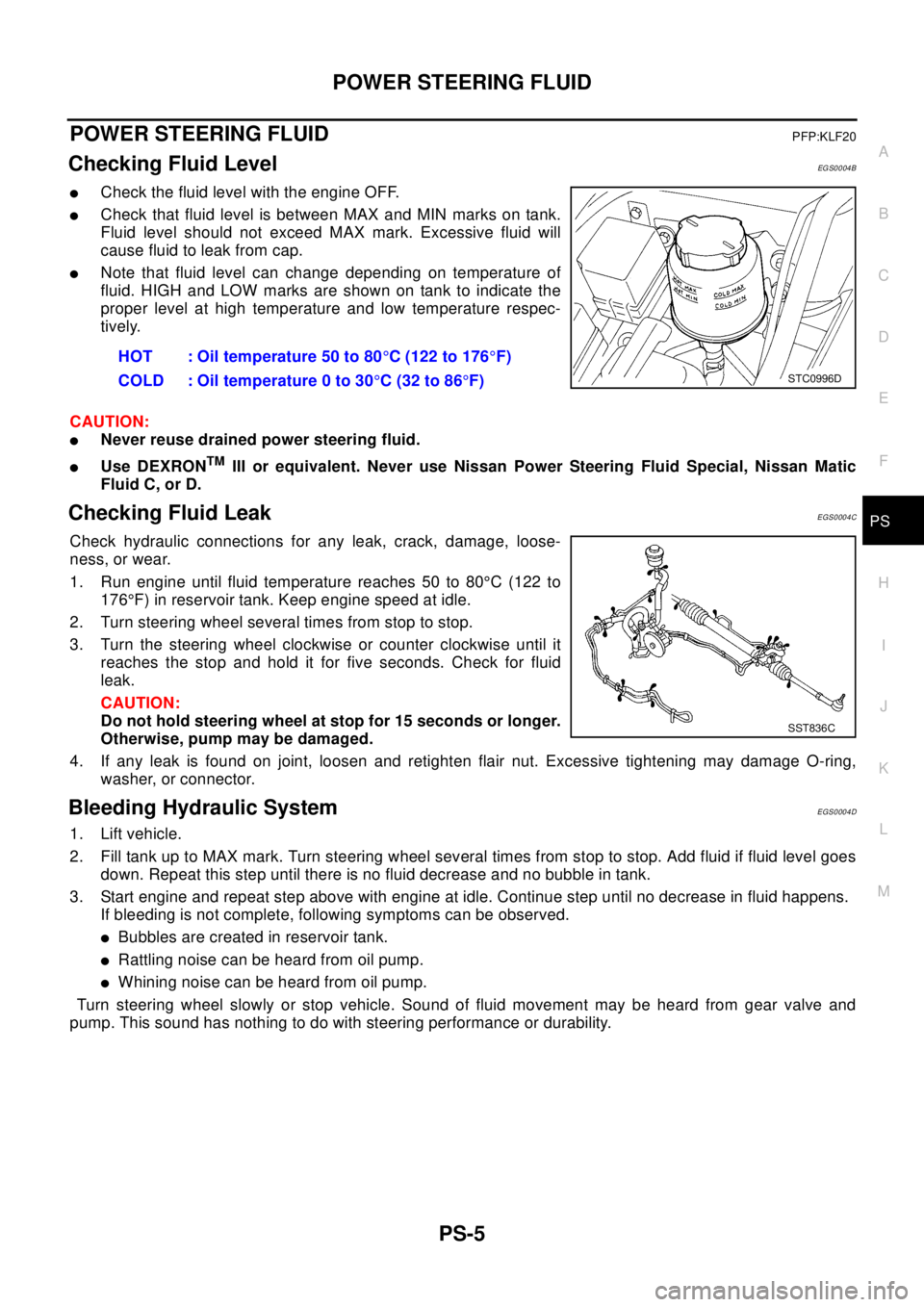
lCheck the fluid level with the engine OFF.
lCheck that fluid level is between MAX and MIN marks on tank.
Fluid level should not exceed MAX mark. Excessive fluid will
cause fluid to leak from cap.
lNote that fluid level can change depending on temperature of
fluid. HIGH and LOW marks are shown on tank to indicate the
proper level at high temperature and low temperature respec-
tively.
CAUTION:
lNever reuse drained power steering fluid.
lUse DEXRONTMIII or equivalent. Never use Nissan Power Steering Fluid Special, Nissan Matic
Fluid C, or D.
Checking Fluid LeakEGS0004C
Check hydraulic connections for any leak, crack, damage, loose-
ness, or wear.
1. Run engine until fluid temperature reaches 50 to 80°C (122 to
176°F) in reservoir tank. Keep engine speed at idle.
2. Turn steering wheel several times from stop to stop.
3. Turn the steering wheel clockwise or counter clockwise until it
reaches the stop and hold it for five seconds. Check for fluid
leak.
CAUTION:
Do not hold steering wheel at stop for 15 seconds or longer.
Otherwise, pump may be damaged.
4. If any leak is found on joint, loosen and retighten flair nut. Excessive tightening may damage O-ring,
washer, or connector.
Bleeding Hydraulic SystemEGS0004D
1. Lift vehicle.
2. Fill tank up to MAX mark. Turn steering wheel several times from stop to stop. Add fluid if fluid level goes
down. Repeat this step until there is no fluid decrease and no bubble in tank.
3. Start engine and repeat step above with engine at idle. Continue step until no decrease in fluid happens.
If bleeding is not complete, following symptoms can be observed.
lBubbles are created in reservoir tank.
lRattling noise can be heard from oil pump.
lWhiningnoisecanbeheardfromoilpump.
Turn steering wheel slowly or stop vehicle. Sound of fluid movement may be heard from gear valve and
pump. This sound has nothing to do with steering performance or durability.HOT : Oil temperature 50 to 80°C (122 to 176°F)
COLD : Oil temperature 0 to 30°C(32to86°F)
STC0996D
SST836C
Page 2766 of 3066
PS-6
STEERING WHEEL
STEERING WHEEL
PFP:48430
On-Vehicle Inspection and ServiceEGS0004E
PLAY INSPECTION
1. Turn steering wheel to straight-ahead position. Start engine and lightly turn steering wheel clockwise and
counter clockwise until front wheels start moving. Measure travel to starting point on circumference of
steering wheel.
2. If play is outside specifications, check following parts for proper installation: steering gear assembly, front
suspension, axles, and steering column
lCheck steering wheel for vertical, horizontal, or axial play.
lLift vehicle and check steering gear mounting bolts and nuts for looseness.
NEUTRAL POSITION INSPECTION
lAfter the wheel alignment inspection, carry out the neutral position inspection. Refer toWT-4.
lBefore removing steering wheel, check steering gear neutral position.
1. Set vehicle to straight-ahead position, and check that steering wheel is in neutral position.
2. If it is not in neutral position, remove steering wheel, and install again in properly.
3. If it is not adjusted within two teeth from center of gear, loosen tie rod lock nut. Then turn it to opposite
direction to adjust until amount of left and right becomes equal.
STEERING TORQUE CHECK
1. Stop vehicle on a dry flat paved road and apply parking brake.
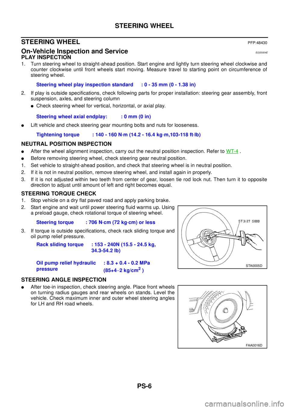
2. Start engine and wait until power steering fluid warms up. Using
a preload gauge, check rotational torque of steering wheel.
3. If torque is outside specifications, check rack sliding torque and
oil pump relief pressure.
STEERING ANGLE INSPECTION
lAfter toe-in inspection, check steering angle. Place front wheels
on turning radius gauges and rear wheels on stands. Level the
vehicle. Check maximum inner and outer wheel steering angles
for LH and RH road wheels.Steering wheel play inspection standard : 0 - 35 mm (0 - 1.38 in)
Steering wheel axial endplay: : 0 mm (0 in)
Tightening torque : 140 - 160 N·m (14.2 - 16.4 kg·m,103-118 ft·lb)
Steering torque : 706 N·cm (72 kg·cm) or less
Rack sliding torque : 153 - 240N (15.5 - 24.5 kg,
34.3-54.2 lb)
Oil pump relief hydraulic
pressure: 8.3 + 0.4 - 0.2 MPa
(85+4-2kg/cm
2)
STA0005D
FAA0016D
Page 2783 of 3066
POWER STEERING OIL PUMP
PS-23
C
D
E
F
H
I
J
K
L
MA
B
PS
POWER STEERING OIL PUMPPFP:49110
On-Vehicle Inspection and ServiceEGS000AF
OIL PUMP PULLEY HYDRAULIC PRESSURE INSPECTION
Before starting following procedure, check tension of belt.
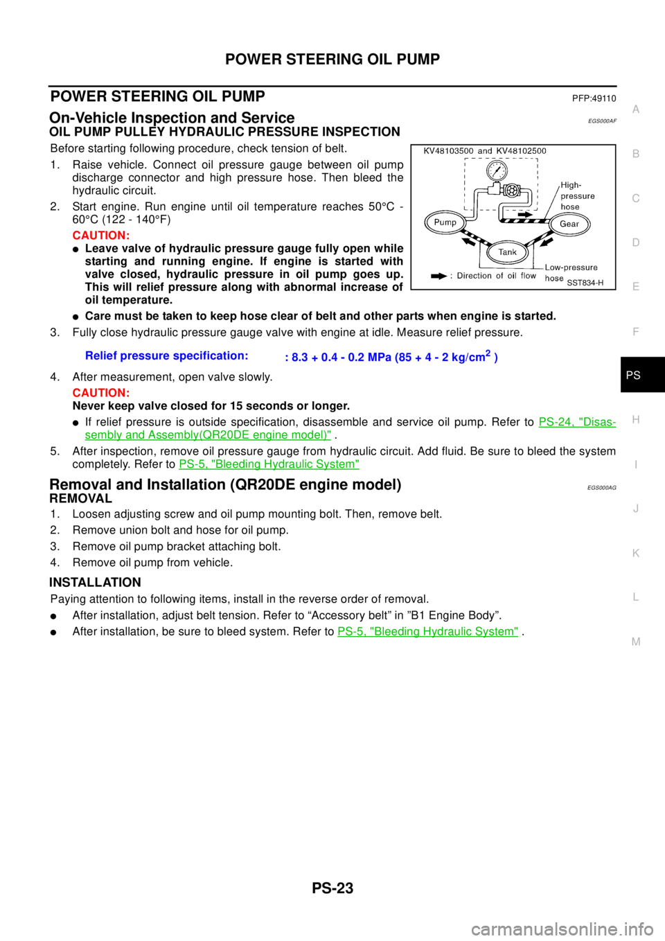
1. Raise vehicle. Connect oil pressure gauge between oil pump
discharge connector and high pressure hose. Then bleed the
hydraulic circuit.
2. Start engine. Run engine until oil temperature reaches 50°C-
60°C (122 - 140°F)
CAUTION:
lLeave valve of hydraulic pressure gauge fully open while
starting and running engine. If engine is started with
valve closed, hydraulic pressure in oil pump goes up.
This will relief pressure along with abnormal increase of
oil temperature.
lCare must be taken to keep hose clear of belt and other parts when engine is started.
3. Fully close hydraulic pressure gauge valve with engine at idle. Measure relief pressure.
4. After measurement, open valve slowly.
CAUTION:
Never keep valve closed for 15 seconds or longer.
lIf relief pressure is outside specification, disassemble and service oil pump. Refer toPS-24, "Disas-
sembly and Assembly(QR20DE engine model)".
5. After inspection, remove oil pressure gauge from hydraulic circuit. Add fluid. Be sure to bleed the system
completely. Refer toPS-5, "
Bleeding Hydraulic System"
Removal and Installation (QR20DE engine model)EGS000AG
REMOVAL
1. Loosen adjusting screw and oil pump mounting bolt. Then, remove belt.
2. Remove union bolt and hose for oil pump.
3. Remove oil pump bracket attaching bolt.
4. Remove oil pump from vehicle.
INSTALLATION
Paying attention to following items, install in the reverse order of removal.
lAfter installation, adjust belt tension. Refer to “Accessory belt” in ”B1 Engine Body”.
lAfter installation, be sure to bleed system. Refer toPS-5, "Bleeding Hydraulic System". Relief pressure specification:
: 8.3 + 0.4 - 0.2 MPa (85 + 4 - 2 kg/cm
2)
SST834-H
Page 2787 of 3066
POWER STEERING OIL PUMP
PS-27
C
D
E
F
H
I
J
K
L
MA
B
PS
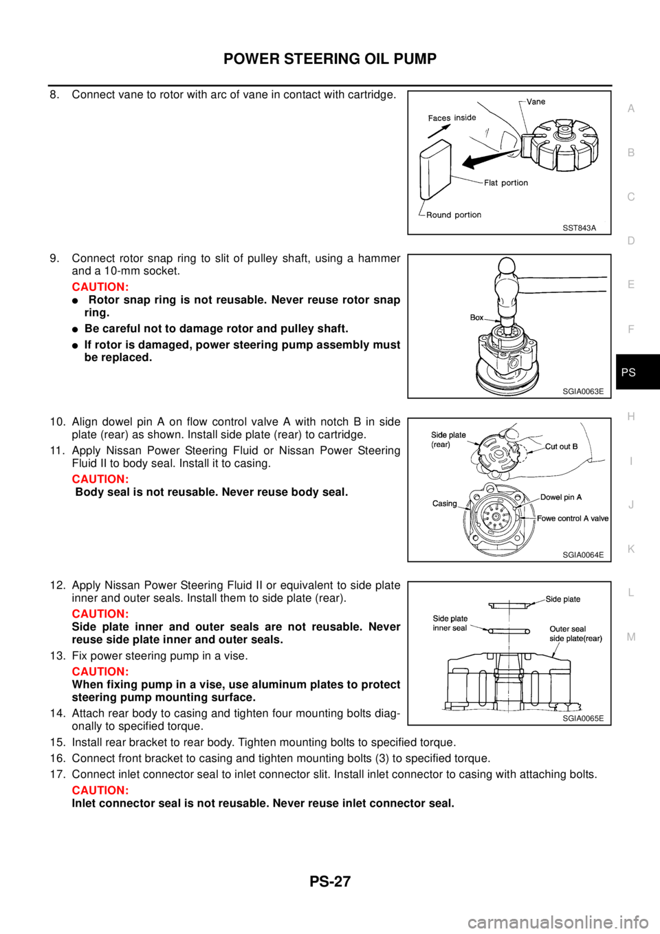
8. Connect vane to rotor with arc of vane in contact with cartridge.
9. Connect rotor snap ring to slit of pulley shaft, using a hammer
and a 10-mm socket.
CAUTION:
lRotor snap ring is not reusable. Never reuse rotor snap
ring.
lBe careful not to damage rotor and pulley shaft.
lIf rotor is damaged, power steering pump assembly must
be replaced.
10. Align dowel pin A on flow control valve A with notch B in side
plate (rear) as shown. Install side plate (rear) to cartridge.
11. Apply Nissan Power Steering Fluid or Nissan Power Steering
Fluid II to body seal. Install it to casing.
CAUTION:
Body seal is not reusable. Never reuse body seal.
12. Apply Nissan Power Steering Fluid II or equivalent to side plate
inner and outer seals. Install them to side plate (rear).
CAUTION:
Side plate inner and outer seals are not reusable. Never
reuse side plate inner and outer seals.
13. Fix power steering pump in a vise.
CAUTION:
When fixing pump in a vise, use aluminum plates to protect
steering pump mounting surface.
14. Attach rear body to casing and tighten four mounting bolts diag-
onally to specified torque.
15. Install rear bracket to rear body. Tighten mounting bolts to specified torque.
16. Connect front bracket to casing and tighten mounting bolts (3) to specified torque.
17. Connect inlet connector seal to inlet connector slit. Install inlet connector to casing with attaching bolts.
CAUTION:
Inlet connector seal is not reusable. Never reuse inlet connector seal.
SST843A
SGIA0063E
SGIA0064E
SGIA0065E
Page 2791 of 3066
POWER STEERING OIL PUMP
PS-31
C
D
E
F
H
I
J
K
L
MA
B
PS
INSPECTION AFTER DISASSEMBLY
lIf pulley is cracked or deformed, replace it.
lIf an oil leak is found around pulley shaft oil seal, replace the seal.
lIf serration on pulley or pulley shaft is deformed or worn, replace it.
ASSEMBLY
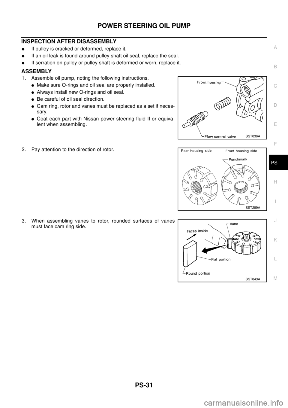
1. Assemble oil pump, noting the following instructions.
lMake sure O-rings and oil seal are properly installed.
lAlways install new O-rings and oil seal.
lBe careful of oil seal direction.
lCam ring, rotor and vanes must be replaced as a set if neces-
sary.
lCoat each part with Nissan power steering fluid II or equiva-
lent when assembling.
2. Pay attention to the direction of rotor.
3. When assembling vanes to rotor, rounded surfaces of vanes
must face cam ring side.
SST036A
SST289A
SST843A
Page 2796 of 3066
PS-36
SERVICE DATA AND SPECIFICATIONS (SDS)
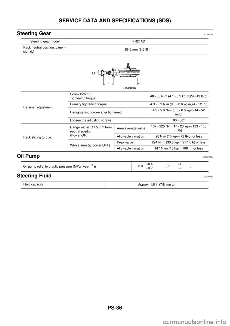
Steering Gear
EGS0004T
Oil PumpEGS0004U
Steering FluidEGS0004V
Steering gear model PR24AD
Rack neutral position, dimen-
sion (L)66.5 mm (2.618 in)
Retainer adjustmentScrew lock nut
Tightening torque40 - 58 N·m (4.1 - 5.9 kg·m,29 - 43 ft·lb)
Primary tightening torque 4.9 - 5.9 N·m (0.5 - 0.6 kg·m,44 - 52 in·)
Re-tightening torque after tightened4.9 - 5.9 N·m (0.5 - 0.6 kg·m 44 - 52
in·lb)
Loosen the adjusting screws. 60 - 80°
Rack sliding torque:Range within±11 .5 m m f r o m
neutral position
(Power ON)Area average value167 - 225 N·m (17 - 23 kg·m,123 - 166
ft·lb)
Allowable variation 98 N·m (10 kg·m,72 ft·lb) or less
Whole area (at power OFF)Peak value 294 N· m (30.0 kg·m,217 ft·lb) or less
Allowable variation 147 N ·m (15 kg·m,108 ft·) or less
STC0101D
Oil pump relief hydraulic pressure (MPa (kg/cm2))8.3+0.4
-0.2(85+4
-2)
Fluid capacity
Approx. 1.0 (7/8 lmp qt)