2003 NISSAN X-TRAIL mirror
[x] Cancel search: mirrorPage 2354 of 3066
DOOR MIRROR
GW-51
C
D
E
F
G
H
J
K
L
MA
B
GW
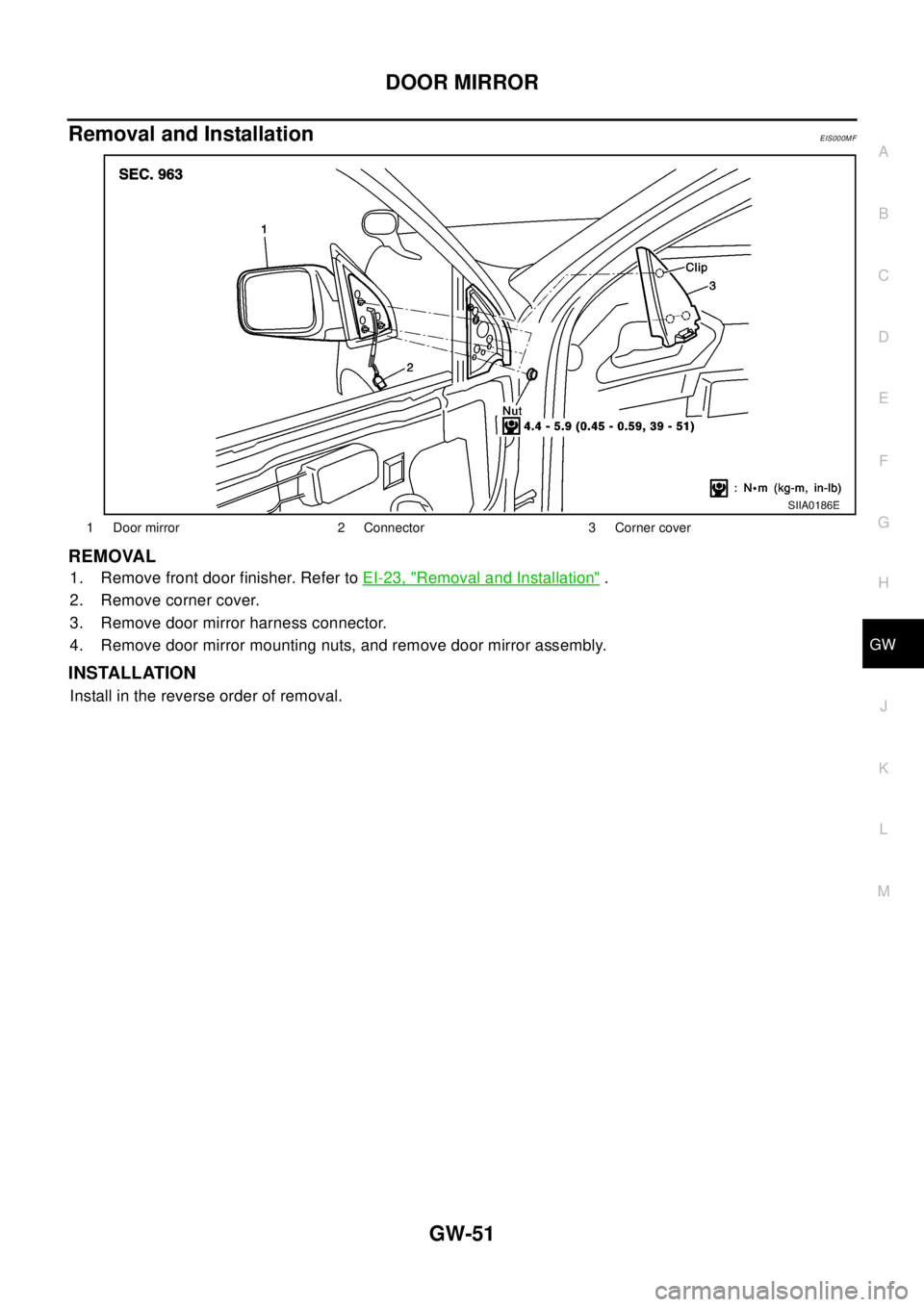
Removal and InstallationEIS000MF
REMOVAL
1. Remove front door finisher. Refer toEI-23, "Removal and Installation".
2. Remove corner cover.
3. Remove door mirror harness connector.
4. Remove door mirror mounting nuts, and remove door mirror assembly.
INSTALLATION
Install in the reverse order of removal.
1 Door mirror 2 Connector 3 Corner cover
SIIA0186E
Page 2355 of 3066
GW-52
DOOR MIRROR
Disassembly and Assembly
EIS000MG
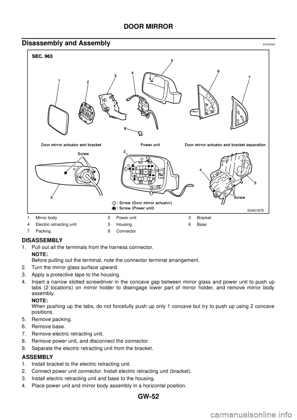
DISASSEMBLY
1. Pull out all the terminals from the harness connector.
NOTE:
Before pulling out the terminal, note the connector terminal arrangement.
2. Turn the mirror glass surface upward.
3. Apply a protective tape to the housing.
4. Insert a narrow slotted screwdriver in the concave gap between mirror glass and power unit to push up
tabs (2 locations) on mirror holder to disengage lower part of mirror holder, and remove mirror body
assembly.
NOTE:
When pushing up the tabs, do not forcefully push up only 1 concave but try to push up using 2 concave
positions.
5. Remove packing.
6. Remove base.
7. Remove electric retracting unit.
8. Remove power unit, and disconnect the connector.
9. Separate the electric retracting unit from the bracket.
ASSEMBLY
1. Install bracket to the electric retracting unit.
2. Connect power unit connector. Install electric retracting unit (bracket).
3. Install electric retracting unit and base to the housing.
4. Place power unit and mirror body assembly in a horizontal position.
1 Mirror body 2 Power unit 3 Bracket
4 Electric retracting unit 5 Housing 6 Base
7 Packing 8 Connector
SIIA0187E
Page 2356 of 3066
DOOR MIRROR
GW-53
C
D
E
F
G
H
J
K
L
MA
B
GW
5. Engage upper tabs of mirror glass with power unit. Then, press lower part of mirror glass down until the
lower part snaps to allow engagement of lower tabs.
NOTE:
After installation, visually check that the lower tabs (2) are securely engaged when viewed from the bot-
tom of mirror surface.
6. Install the packing to the base.
7. Insert the harness terminal into the connector.
NOTE:
Make sure to insert the harness terminal into the correct connector. Do not confuse the locations.
Page 2357 of 3066

GW-54
DOOR MIRROR
Page 2361 of 3066

IDX-4
ALPHABETICAL INDEX
Diagnostic trouble code (DTC) ........................EC-666
Diagnostic trouble code (DTC) for OBD systemEC-12,
EC-38
,EC-379,EC-401,EC-654
Diagnostic trouble code (DTC) inspection priority chart
EC-61
,EC-410
Differential gear (FF M/T) .....................MT-22,MT-27
DLC - Wiring diagram ........................EC-371,EC-646
Door glass ...........................................GW-41,GW-43
Door glass Fitting Adjustment .............GW-41,GW-43
Door lock .................................................BL-54,BL-57
Door mirror ........................................................GW-46
Door trim .............................................................EI-23
Door, front ............................................................BL-8
Door, rear .............................................................BL-8
Drive belt inspection(QR20DE) .........................MA-20
Drive belt inspection(YD22DDTi) ......................MA-27
Drive belt(QR20DE) ..........................................EM-13
Drive belt(YD22DDTi) .....................................EM-110
Drive shaft (front) .............................................FAX-11
Drive shaft (rear) ...............................................RAX-9
Driver air bag ..................................................SRS-27
Dropping resistor (A/T) ......................AT-192,AT-442
DTC work support ..............................................EC-95
DTRL - Wiring diagram .........................................LT-9
Dual pressure switch ........ATC-16,ATC-81,ATC-138
Duct and grilles ...............................ATC-121,MTC-29
E
ECM input/output signal .......................EC-79
,EC-427
ECM power supplyEC-108,EC-256,EC-454,EC-530,
EC-700
ECM relay ........................................................EC-790
ECM/PW - Wiring diagram .................EC-257,EC-531
ECMRLY - Wiring diagram ..............................EC-791
ECTS - Wiring diagram .......EC-143,EC-472,EC-712
EDU - Wiring diagram ......................................EC-756
EGR function ...................................................EC-803
EGR volume control valve ...............................EC-803
EGRC/V - Wiring diagram ................................EC-805
Electric sun roof ...................................................RF-2
Electric throttle control actuator ........EC-271,EC-273,
EC-534
,EC-536
Electrical unit .....................................................PG-73
Electrical units location ......................................PG-64
Electronic drive unit (EDU) ..............................EC-754
Electronic fuel injection pump(YD22DDTi) .....EM-138
Electronic ignition (EI) system .............EC-27,EC-392
Engine control circuit diagramEC-77,EC-425,EC-683
Engine control component parts location ..........EC-73,
EC-421
Engine control module (ECM) ...........EC-249,EC-523,
EC-788
Engine control system diagram and chart ........EC-22,
EC-387
,EC-659
Engine coolant temperature sensor (ECTS) ...EC-141,
EC-470
,EC-711
Engine coolant(QR20DE) ...................................CO-9
Engine coolant(YD22DDTi) ..............................CO-30
Engine fail-safe system .......................EC-62,EC-411
Engine oil filter replacement(QR20DE) .............MA-24
Engine oil filter replacement(YD22DDTi) ..........MA-33
Engine oil replacement(QR20DE) ....................MA-24
Engine oil replacement(YD22DDTi) ..................MA-32
Engine oil(QR20DE) ............................................LU-7
Engine oil(YD22DDTi) .......................................LU-18
Engine removal(QR20DE) ................................EM-61
Engine removal(YD22DDTi) ...........................EM-184
EVAP canister purge volume control solenoid valve ....
EC-233
,EC-372,EC-601,EC-649
EVAP vapor lines inspection(QR20DE) ............MA-26
Evaporative emission (EVAP) systemEC-372,EC-647
Evaporator ....................................................ATC-139
Exhaust manifold(QR20DE) .............................EM-22
Exhaust manifold(YD22DDTi) .........................EM-119
Exhaust system ...................................................EX-2
Exhaust system inspection .....................EX-2,MA-35
Expansion valve ............................................ATC-140
ExteriorEI-13,EI-14,EI-16,EI-17,EI-18,EI-19,EI-21,
EI-22
F
F/FOG - Wiring diagram .........................LT-33
,LT-34
F/PUMP - Wiring diagram .................EC-354,EC-629
Fan control amp. .............................ATC-70,ATC-113
Fan switch ........................................ATC-27,MTC-17
FIAR - Wiring diagram .....................................EC-778
Final drive (FF M/T) ..............................MT-22,MT-27
Final drive disassembly ..................................RFD-11
Final drive removal and installation ................RFD-11
Finisher, interior - See Trim ......................EI-23,EI-25
Finisher, rear panel .............................................EI-22
Floor trim .............................................................EI-28
Fluid temperature sensor (A/T) ........................AT-141
Fluids ................................................................MA-17
Fluorescent leak detector .............................ATC-141
Flywheel (clutch) ................................................CL-15
Flywheel runout(QR20DE) ................................EM-89
Flywheel runout(YD22DDTi) ...........................EM-208
Fog lamp, front ...................................................LT-33
Fork rod (M/T) .......................................MT-21,MT-26
Freeze frame data ..............................EC-39,EC-402
FRO2 - Wiring diagram ....................................EC-582
FRO2/H - Wiring diagram ................................EC-569
Front bumper ........................................................EI-6
Front disc brake .................................................BR-21
Front door ............................................................BL-8
Front Door Trim ..................................................EI-23
Front fog lamp ....................................................LT-33
Front passenger air bag ..................................SRS-33
Front seat .............................................................SE-7
Front seat belt ......................................................SB-3
Front seat belt pre-tensioner .....SB-2,SRS-3,SRS-38
Front side air bag ............................................SRS-35
Front suspension ..............................................FSU-5
Page 2362 of 3066
IDX-5
A
C
D
E
F
G
H
I
J
K
L B
IDX
ALPHABETICAL INDEX
Front washer ......................................................WW-4
Front wiper .........................................................WW-4
FTS - Wiring diagram ......................................EC-752
Fuel check valve ..............................................EC-372
Fuel cut control (at no load high engine speed)EC-28,
EC-393
,EC-662
Fuel filler lid ........................................................BL-64
Fuel filter ..........................................................EC-664
Fuel filter replacement(QR20DE) .........................FL-4
Fuel filter replacement(YD22DDTi) .......FL-15,MA-30
Fuel gauge ..................................................DI-4,DI-22
Fuel injection control system ...........................EC-660
Fuel injection system .........................EC-194,EC-200
Fuel injector .....................................................EC-727
Fuel injector adjustment resistor ......................EC-777
Fuel injector and fuel tube(QR20DE) ................EM-29
Fuel injector and fuel tube(YD22DDTi) ............EM-135
Fuel leak ..........................................................EC-781
Fuel line inspection(QR20DE) .................FL-3,MA-23
Fuel line inspection(YD22DDTi) ............FL-14,MA-30
Fuel pressure check ............................EC-34,EC-399
Fuel pressure release ..........................EC-34,EC-399
Fuel pressure relief valve ................................EC-665
Fuel pump ..........................................EC-352,EC-627
Fuel pump and gauge(QR20DE) ..........................FL-4
Fuel system(QR20DE) .........................................FL-3
Fuel system(YD22DDTi) .....................................FL-14
Fuel tank(QR20DE) ..............................................FL-9
Fuel tank(YD22DDTi) .........................................FL-21
Fuel temperature sensor .................................EC-751
Fuse ...................................................................PG-12
Fuse and fusible link box ...................................PG-77
Fusible link .........................................................PG-12
G
Gear components (M/T) .......................MT-19
,MT-24
Generator ..........................................................SC-12
Generator - See Alternator ................................SC-12
Generic scan tool (GST) ....................................EC-96
Glass ..................................................GW-41,GW-43
GLOW - Wiring diagram ..................................EC-797
Glow plug .........................................................EC-796
Glow plug(YD22DDTi) .....................................EM-130
Glow relay ........................................................EC-796
Grease ...............................................................MA-17
Grille - See Exterior .............................................EI-11
Ground distribution ............................................PG-13
G-sensor .............................................................TF-50
H
H/AIM - Wiring diagram ......................................LT-15
H/LAMP - Wiring diagram ...........................LT-4,LT-5
H/MIRROR - Wiring diagram ............................GW-10
Harness connector ............................................PG-70
Harness layout ...................................................PG-29
Headlamp .............................................................LT-4
Headlamp aiming control ....................................LT-15
Headlamp leveler - See Headlamp aiming control .......
LT-15
Headlamp washer ............................................WW-19
Headlining - See Roof trim ..................................EI-29
Heated oxygen sensor 1 ....EC-160,EC-166,EC-174,
EC-284
,EC-290,EC-490,EC-581
Heated oxygen sensor 1 heater .........EC-120,EC-568
Heated oxygen sensor 2 ....EC-181,EC-187,EC-296,
EC-303
,EC-587
Heated oxygen sensor 2 heater .........EC-125,EC-573
Heated seat ...............................................SE-3,SE-5
HEATER - Wiring diagram ................................MTC-6
Heater and cooling unit (Heater core) ............ATC-115
Heater mirror .....................................................GW-10
Heater system - Wiring diagram .......................MTC-6
Heater unit (heater core) ..ATC-120,MTC-23,MTC-26
HFC134a (R134a) system precaution ...............ATC-4
HFC134a (R134a) system service procedureATC-123
HFC134a (R134a) system service tools ..........ATC-12
HFC134a system service equipment precautionATC-8
HO2S1 - Wiring diaram ......EC-122,EC-162,EC-169,
EC-177
,EC-492
HO2S2 - Wiring diagram ....EC-183,EC-190,EC-299,
EC-306
HO2S2H - Wiring diagram ...............................EC-127
Hood ....................................................................BL-4
Horn .................................................................WW-23
HORN - Wiring diagram ...................................WW-23
How to erase DTC ...........................................EC-666
HowtoeraseDTCforOBDsystem .....EC-46,EC-402
I
IATS - Wiring diagram .....................................EC-138
IATSEN - Wiring diagram ................................EC-578
Identification .....................................................ATC-10
Idle air volume learning ........................EC-31,EC-396
Idle speed .............................EC-64,EC-412,EC-672
IGN/SG - Wiring diagram .................................EC-335
Ignition coil .........................................EC-334,EC-592
Ignition coil(QR20DE) .......................................EM-27
Ignition control system .......................EC-334,EC-592
Ignition timing .......................................EC-64,EC-412
IGNSYS - Wiring diagram ................................EC-593
ILL - Wiring diagram ...........................................LT-45
Illumination ..........................................................LT-45
In vehicle sensor ...............ATC-95,ATC-97,ATC-106
INJECT - Wiring diagram ....EC-344,EC-619,EC-730
Injection nozzle(YD22DDTi) ...........................EM-135
Injector ...............................................EC-343,EC-618
Input shaft (FF M/T) ..............................MT-19,MT-24
Instrument panel ...................................................IP-3
INT/L - Wiring diagram ........................................LT-65
Intake air temparature sensor ............EC-136,EC-577
Intake door control linkage adjustment ............ATC-66
Intake door motorATC-64,ATC-112,MTC-10,MTC-22
Intake manifold(QR20DE) .................................EM-17
Page 2363 of 3066

IDX-6
ALPHABETICAL INDEX
Intake manifold(YD22DDTi) ............................EM-115
Intake sensor ................................ATC-101,ATC-108
Intake valve timing control .................EC-117,EC-608
Intake valve timing control solenoid valve ......EC-266,
EC-608
Interior .......................EI-23,EI-25,EI-26,EI-28,EI-29
Interior lamp ........................................................LT-55
Interior lamp on-off control ......................LT-55,LT-56
ISO 15031-5 Mode 1 - 9 ....................................EC-36
IVC - Wiring diagram .......................................EC-268
IVC/V - Wiring diagram ....................................EC-610
J
Joint connector (J/C) .............................PG-72
,PG-76
K
Keyless entry system - See Multi-remote control system
BL-45
Knock sensor (KS) .............................EC-212,EC-496
KS - Wiring diagram ...........................EC-214,EC-498
L
LAN system circuit ...........................................ATC-56
License lamp .......................................................LT-30
Line pressure solenoid valve ...........................AT-179
Line pressure test (A/T) .......................AT-68,AT-290
Liquid gasket application(QR20DE) ....................EM-6
Liquid gasket application(YD22DDTi) .............EM-103
LOAD - Wiring diagram ......................EC-363,EC-638
Location of electrical units .................................PG-64
Lock, door ...............................................BL-54,BL-57
Lubricant (R134a) A/C ........................ATC-5,ATC-21
Lubricants .........................................................MA-17
Lubrication circuit (engine)(QR20DE) ..................LU-5
Lubrication circuit (engine)(YD22DDTi) .............LU-17
Lubrication-locks, hinges and hood latches ......MA-42
M
M/T major overhaul ...............................MT-27
,MT-35
M/T oil replacement ...........................................MT-11
M/T removal and installation ..............................MT-16
MAFS - Wiring diagram .....EC-132,EC-262,EC-466,
EC-708
Magnet clutch .................................ATC-73,ATC-129
MAIN - Wiring diagram .......EC-108,EC-454,EC-701
Mainshaft (M/T) .....................................MT-19,MT-24
Major overhaul (Transfer) ..................................TF-14
Malfunction indicator (MI) ...EC-252,EC-526,EC-667
Malfunction indicator lamp (MIL) ..........EC-48,EC-404
Mass air flow sensor (MAFS) ............EC-130,EC-260,
EC-463
,EC-706
Master cylinder (brake) ......................................BR-13
Master cylinder (clutch) ........................................CL-9
METER - Wiring diagram ...........................DI-8,DI-26
MIL - Wiring diagram ........................EC-253,EC-527
MIL/DL - Wiring diagram ..................................EC-825
MIRROR - Wiring diagram ...............................GW-47
Mirror defogger ................................................GW-10
Mirror, door ......................................................GW-46
Mirror, out side .................................................GW-46
Misfire ..............................................................EC-206
Mode door control linkage adjustment ...........ATC-61,
ATC-118
,MTC-8,MTC-27
Mode door motor ............................ATC-58,ATC-118
Molding - See Exterior ........GW-3,EI-14,EI-16,EI-17
Mud guard - See Exterior ....................................EI-16
MULTI - Wiring diagram .....................................BL-47
Multiport fuel injection (MFI) system ...EC-24,EC-389
Multi-remote control system ...............................BL-45
N
NATS - Wiring diagram ......................................BL-72
NATS (Nissan anti-theft system) .......................BL-70
NVH troubleshooting (BR) .........................BR-5,PB-2
NVH troubleshooting (CL) ....................................CL-4
NVH troubleshooting (EM)(QR20DE) ...............EM-11
NVH troubleshooting (EM)(YD22DDTi) ..........EM-108
NVH troubleshooting (FSU) ..............................FSU-4
NVH troubleshooting (M/T) .................................MT-8
NVH troubleshooting (PR) .................................FAX-6
NVH troubleshooting (RA) ................................RAX-5
NVH troubleshooting (RAX) ..............................RAX-5
NVH troubleshooting (RSU) ..............................RSU-4
NVH troubleshooting (ST) ....................................PS-4
NVH troubleshooting (Transfer) ...........................TF-7
NVH troubleshooting (WT) ..................................WT-2
O
Oil cooler (engine)(QR20DE) .............................LU-13
Oil cooler (engine)(YD22DDTi) ..........................LU-25
Oil filter(QR20DE) ................................................LU-9
Oil filter(YD22DDTi) ...........................................LU-20
Oil pan (engine)(QR20DE) ...............................EM-24
Oil pan (engine)(YD22DDTi) ...........................EM-125
Oil pressure (engine)(QR20DE) ..........................LU-7
Oil pressure (engine)(YD22DDTi) ......................LU-18
Oil pump (engine)(QR20DE) .............................LU-10
Oil pump (engine)(YD22DDTi) ...........................LU-23
Oil pump regulator valve (engine)(QR20DE) .....LU-11
Oil pump regulator valve (engine)(YD22DDTi) ..LU-24
On board diagnostic system ...............EC-36,EC-401
Operating cylinder (clutch) .................................CL-11
Out side mirror .................................................GW-46
Overdrive control switch ....................AT-265,AT-387
Overheat ..........................................................EC-761
Oversize piston(QR20DE) ................................EM-85
Oversize piston(YD22DDTi) ...........................EM-204
Page 2367 of 3066
IP-1
INSTRUMENT PANEL
IBODY
CONTENTS
C
D
E
F
G
H
J
K
L
M
SECTION
A
B
IP
INSTRUMENT PANEL
PRECAUTIONS .......................................................... 2
Precautions for Supplemental Restraint System
(SRS) “AIR BAG” and “SEAT BELT PRE-TEN-
SIONER” .................................................................. 2
Precautions .............................................................. 2
INSTRUMENT PANEL ASSEMBLY ........................... 3
Component Parts Drawing ....................................... 3
Removal and Installation .......................................... 5
TABLE OF WORK ITEM ....................................... 5
FRONT SPEAKER GRILLE .................................. 6
INSTRUMENT FINISHER ..................................... 6
CUP HOLDER ....................................................... 6
CLUSTER LID A ................................................... 6
COMBINATION METER ....................................... 6
GPS ANTENNA .................................................... 6
POCKET ............................................................... 6
STEERING COLUMN COVER ............................. 6
INSTRUMENT LOWER DRIVER PANEL ............. 7
MIRROR CONTROL SWITCH .............................. 7CLUSTER LID C ................................................... 7
AUDIO UNIT AND POCKET ................................. 7
CLUSTER LID FINISHER ..................................... 7
A/T OR M/T FINISHER ......................................... 8
CENTER CONSOLE ............................................. 8
CD AUTO–CHANGER AND POCKET .................. 8
HEATER CONTROL FINISHER ............................ 8
HEATER CONTROLLER ....................................... 8
LOWER INSTRUMENT COVER ........................... 8
INSTRUMENT LOWER CENTER PANEL ............ 8
GLOVE BOX ......................................................... 9
LOWER INSTRUMENT PANEL ............................ 9
GLOVE BOX COVER ............................................ 9
FRONT PASSENGER AIR BAG MODULE ........... 9
INSTRUMENT MASK ............................................ 9
FRONT PILLAR GARNISH ................................... 9
INSTRUMENT PANEL .......................................... 9
Disassembly and Assembly .................................... 10
CONSOLE BOX ASSEMBLY .............................. 10