2003 NISSAN X-TRAIL engine oil
[x] Cancel search: engine oilPage 2165 of 3066
![NISSAN X-TRAIL 2003 Electronic Repair Manual CYLINDER BLOCK
EM-195
[YD22DDTi]
C
D
E
F
G
H
I
J
K
L
MA
EM
12. Install connecting rod bearings to connecting rods and caps.
lWhile installing connecting rod bearings, apply engine oil to
bearing surfa NISSAN X-TRAIL 2003 Electronic Repair Manual CYLINDER BLOCK
EM-195
[YD22DDTi]
C
D
E
F
G
H
I
J
K
L
MA
EM
12. Install connecting rod bearings to connecting rods and caps.
lWhile installing connecting rod bearings, apply engine oil to
bearing surfa](/manual-img/5/57402/w960_57402-2164.png)
CYLINDER BLOCK
EM-195
[YD22DDTi]
C
D
E
F
G
H
I
J
K
L
MA
EM
12. Install connecting rod bearings to connecting rods and caps.
lWhile installing connecting rod bearings, apply engine oil to
bearing surfaces (inside). Do not apply oil to rear surfaces,
but clean them completely.
lAlign stoppers on connecting rod bearings with connecting
rod stopper notches to install connecting rod bearings.
13. Install piston and connecting rod assembly to crankshaft.
lMove crankshaft pin to be assembled to BDC.
lAlign cylinder position with cylinder No. on connecting rod to
install piston and connecting rod assembly.
lUsing piston ring compressor, install piston and connecting
rod assembly with front mark on piston crown facing toward
the front side of engine.
CAUTION:
When installing piston and connecting rod assembly, pre-
vent the big end of connecting rod from interfering with oil
jet.
14. Install connecting rod caps and mounting nuts.
lAlign cylinder No. stamped on connecting rod with that on cap
to install connecting rod cap.
lMake sure that the front mark on connecting rod cap faces
towards the front of the engine.
15. Tighten connecting rod nuts according to the following proce-
dure:
a. Apply engine oil on bolt threads and seat surface of nuts.
b. Tighten to 29 to 30 N·m (2.9 to 3.1 kg-m, 21 to 22 ft-lb).
c. Loosen completely to 0 N·m (0 kg-m, 0 in-lb).
d. Tighten to 19 to 20 N·m (1.9 to 2.1 kg-m, 14 to 15 ft-lb).
e. Tighten 120°to 125°[target: 120°]. (angular tightening)
lAlways use either an angle wrench (SST) or protractor
during angular tightening. Avoid tightening based on
visual checks alone.
lAfter tightening nuts, check that crankshaft rotates smoothly.
JEM229G
JEM230G
JEM227G
JEM231G
Page 2166 of 3066
![NISSAN X-TRAIL 2003 Electronic Repair Manual EM-196
[YD22DDTi]
CYLINDER BLOCK
lCheck connecting rod side clearance. Refer toEM-200,
"CONNECTING ROD SIDE CLEARANCE".
16. Force fit rear oil seal into rear oil seal retainer.
lUsing a drift [105 mm NISSAN X-TRAIL 2003 Electronic Repair Manual EM-196
[YD22DDTi]
CYLINDER BLOCK
lCheck connecting rod side clearance. Refer toEM-200,
"CONNECTING ROD SIDE CLEARANCE".
16. Force fit rear oil seal into rear oil seal retainer.
lUsing a drift [105 mm](/manual-img/5/57402/w960_57402-2165.png)
EM-196
[YD22DDTi]
CYLINDER BLOCK
lCheck connecting rod side clearance. Refer toEM-200,
"CONNECTING ROD SIDE CLEARANCE".
16. Force fit rear oil seal into rear oil seal retainer.
lUsing a drift [105 mm (4.13 in) dia.], force fit so that the
dimension is as specified in the figure.
lAvoid inclined fitting. Force fit perpendicularly.
17. Install rear oil seal and retainer assembly.
lApply a continuous bead of liquid gasket to rear oil seal and
retainer assembly as shown in the figure.
18. Press fit pilot bushing into flywheel.
lUsing drift with outer diameter of 19 mm (0.75 in), press fit
pilot bushing until it stops.
19. Install fuel supplypump bracket.
lAlign the bracket with the dowel pins on the block to install.
lThe two bolts used for dowel pins have a longer shanks than
the other two.
20. Install parts to the engine in the reverse order of disassembly.
21. Remove engine from engine stand in the reverse order of
assembly.
22. Install flywheel.
lHolding ring gear with ring stopper (SST), tighten securing
bolts with TORX bit (size: Q6T55 E9, Commercial Service
Tool).
lTighten bolts uniformly in a crisscross manner.
JEM232G
JEM233G
JEM234G
SBIA0200E
Page 2180 of 3066
![NISSAN X-TRAIL 2003 Electronic Repair Manual EM-210
[YD22DDTi]
SERVICE DATA AND SPECIFICATIONS (SDS)
SERVICE DATA AND SPECIFICATIONS (SDS)
PFP:00030
Standard and LimitEBS00BPO
GENERAL SPECIFICATIONS
INTAKE MANIFOLD AND EXHAUST MANIFOLD
Unit: mm NISSAN X-TRAIL 2003 Electronic Repair Manual EM-210
[YD22DDTi]
SERVICE DATA AND SPECIFICATIONS (SDS)
SERVICE DATA AND SPECIFICATIONS (SDS)
PFP:00030
Standard and LimitEBS00BPO
GENERAL SPECIFICATIONS
INTAKE MANIFOLD AND EXHAUST MANIFOLD
Unit: mm](/manual-img/5/57402/w960_57402-2179.png)
EM-210
[YD22DDTi]
SERVICE DATA AND SPECIFICATIONS (SDS)
SERVICE DATA AND SPECIFICATIONS (SDS)
PFP:00030
Standard and LimitEBS00BPO
GENERAL SPECIFICATIONS
INTAKE MANIFOLD AND EXHAUST MANIFOLD
Unit: mm (in)
DRIVE BELTS
Belt Deflection:
Unit: mm (in)
*: When engine is cold.Cylinder arrangementIn-line 4
Displacement
Unit: cm
3(cu in)2,184 (133.27)
Bore and stroke Unit: mm (in) 86 x 94 (3.39 x 3.70)
Valve arrangementDOHC
Firing order1-3-4-2
Number of piston ringsCompression 2
Oil 1
Number of main bearings5
Compression ratio16.0
Compression pressure
Unit:kPa(bar,kg/cm
2,psi)/200rpmStandard 2,893 (28.9, 29.5, 419)
Minimum 2,452 (24.5, 25.0, 356)
Differential limit between cylinders 490 (4.9, 5.0, 71)
Valve timing
Unit: degree
abc de f
224 212 2 30 -2 46
EM120
Item Limit
Surface distortionIntake manifold 0.1 (0.004)
Exhaust manifold 0.3 (0.012)
Applied beltBelt deflection with 98 N (10 kg, 22 lb) force applied*
New Adjusted Limit for re-adjusting
Air conditioner compressor
belt4-5
(0.16 - 0.20)6-7
(0.24 - 0.28)8.5 (0.335)
Alternator & water pump
belt9.0 - 10.5
(0.354 - 0.413)11 . 0 - 1 2 . 5
(0.433 - 0.492)16.5 (0.650)
Page 2190 of 3066
![NISSAN X-TRAIL 2003 Electronic Repair Manual EM-220
[YD22DDTi]
SERVICE DATA AND SPECIFICATIONS (SDS)
M8 bolt 16.0- 19.0 (1.6 - 1.9, 12 - 14)
Injection tube Nozzle side 21.6 - 24.5 (2.2 - 2.5, 16 - 18)
Pump side 26.5 - 29.4 (2.7 - 3.0, 20 - 21)
N NISSAN X-TRAIL 2003 Electronic Repair Manual EM-220
[YD22DDTi]
SERVICE DATA AND SPECIFICATIONS (SDS)
M8 bolt 16.0- 19.0 (1.6 - 1.9, 12 - 14)
Injection tube Nozzle side 21.6 - 24.5 (2.2 - 2.5, 16 - 18)
Pump side 26.5 - 29.4 (2.7 - 3.0, 20 - 21)
N](/manual-img/5/57402/w960_57402-2189.png)
EM-220
[YD22DDTi]
SERVICE DATA AND SPECIFICATIONS (SDS)
M8 bolt 16.0- 19.0 (1.6 - 1.9, 12 - 14)
Injection tube Nozzle side 21.6 - 24.5 (2.2 - 2.5, 16 - 18)
Pump side 26.5 - 29.4 (2.7 - 3.0, 20 - 21)
Nozzle support25.1 - 28.0 (2.6 - 2.8, 19 - 20)
Spill tube Nozzle side 14.7 - 16.7 (1.5 - 1.7, 11 - 12)
Cylinder head side 16.7 - 20.6 (1.7 - 2.1, 13 - 15)
Common rail51.0 - 64.0 (5.2 - 6.5., 38 - 47)
Fuel supply pump46.0 - 56.0 (4.57 - 5.7, 37 - 41)
Fuel supply pump sprocket 37.0 - 41.0 (3.8 - 4.2, 28 - 30)
Fuel supply pump rear bracket 27.0 - 37.0 (2.8 - 3.8, 20 - 27)
Front chain case
6.9 - 8.8 ( 0.7 - 0.9, 61 - 78)*
2
Chain tensioner
8.5 - 10.7 (0.86 - 1.1, 75 - 95)*2
Tensior guide21.0 - 26.0 (2.1 - 2.7, 16 - 19)
Slack guide21.0 - 26.0 (2.1 - 2.7, 16 - 19)
Camshaft sprocket138- 147 (14.0 - 15.0, 102 - 108)
Fuel supply pump sprocket 38.0 -41.0 (3.8 - 4.2, 28 - 30)
Oil pump12 - 13 (1.3 - 1.4, 9 - 10)
Power steering pump51.0 - 56.0 (5.2 - 5.8, 38 - 41)
Rear chain case12.0 - 13.0 (1.2 - 1.4, 19 - 10)
Engine coolant temperature sensor 12.0- 15.0 (1.2 - 1.6, 9- 11)
*1 Cylinder head 1) 29 - 38 (2.9 - 3.9, 21 - 28)
2) 180°to185°
3) 0 (0, 0)
4) 35 to 44 (3.5 - 4.5, 26 - 32)
5) 90°to 95°(angle tightening)
6) 90°to 95°(angle tightening)
Water outlet21 - 28 (2.1 - 2.9, 16 - 20)
Glow plug18.0 - 2.0 (1.8 - 2.2, 13 - 15)
*1 Flywheel103 - 112 (10.5 - 115, 76 - 83)
Oil pressure switch13.0 - 17.0 (1.25 - 1.75, 9 - 12)
Oil jet6.1 - 10.7(0.62 - 1.1, 54 - 95)
Oil jet relief valve40 - 58 (4.0 - 6.0, 29 - 43)
Rear oil seal retainer12.0 - 13.0 (1.2 - 1.4, 9 - 10)
Page 2198 of 3066

FAX-2
PRECAUTIONS
PRECAUTIONS
PFP:00001
CautionEDS0005P
Observe the following precautions when disassembling and servicing drive shaft.
lThe wheel joint cannot be disassembled. Do not attempt to disassemble it.
lPerform work in a location which is as dust-free and dirt-free as possible.
lBefore disassembling and servicing, clean the outside of parts.
lThe disassembly and service location must be clean. Care must be taken to prevent parts from becoming
dirty and to prevent the entry of foreign objects.
lDisassembled parts must be carefully reassembled in the correct order. If work is interrupted, a clean
cover must be placed over parts.
lPaper shop cloths must be used. Fabric shop cloths must not be used because of the danger of lint adher-
ing to parts.
lDisassembled parts (except for rubber parts) should be cleaned with kerosene which shall be removed by
blowing with air or wiping with paper shop cloths.
Precautions for Brake SystemEDS0 00 I0
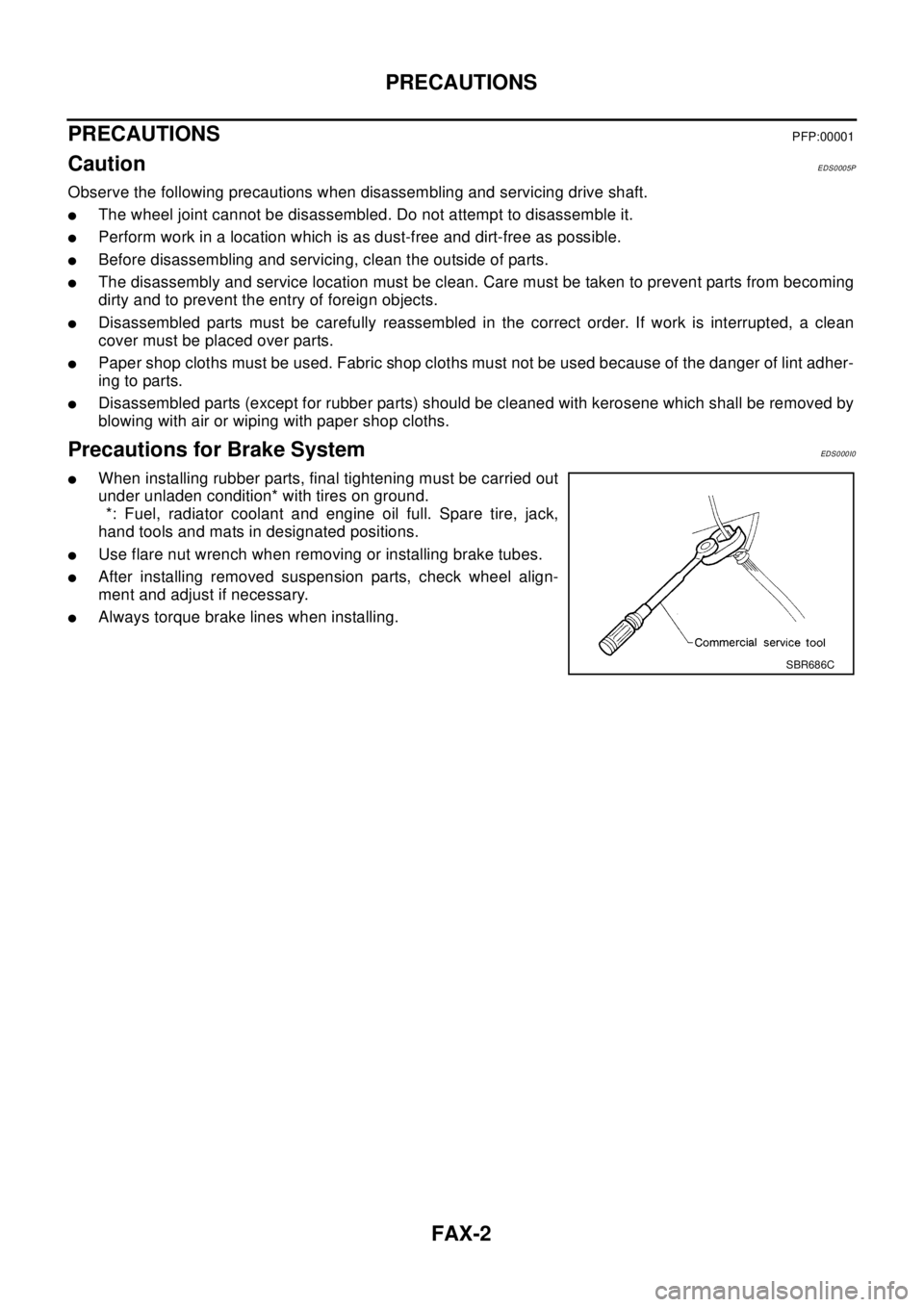
lWhen installing rubber parts, final tightening must be carried out
under unladen condition* with tires on ground.
*: Fuel, radiator coolant and engine oil full. Spare tire, jack,
hand tools and mats in designated positions.
lUse flare nut wrench when removing or installing brake tubes.
lAfter installing removed suspension parts, check wheel align-
ment and adjust if necessary.
lAlways torque brake lines when installing.
SBR686C
Page 2208 of 3066

FAX-12
FRONT DRIVE SHAFT
lDo not allow drive shaft, with transaxle inserted, to hang down without support for counter
shaft, wheel joints, and other parts.
lWhen the drive shafts listed below have been removed, check that a circular clip is attached to the end.
lRemove installation bolt from right-side drive shaft support bearing bracket. Then remove bracket from
engine.
lRemove installation bolt from right-side drive shaft and remove drive shaft from side shaft.
INSPECTION AFTER REMOVAL
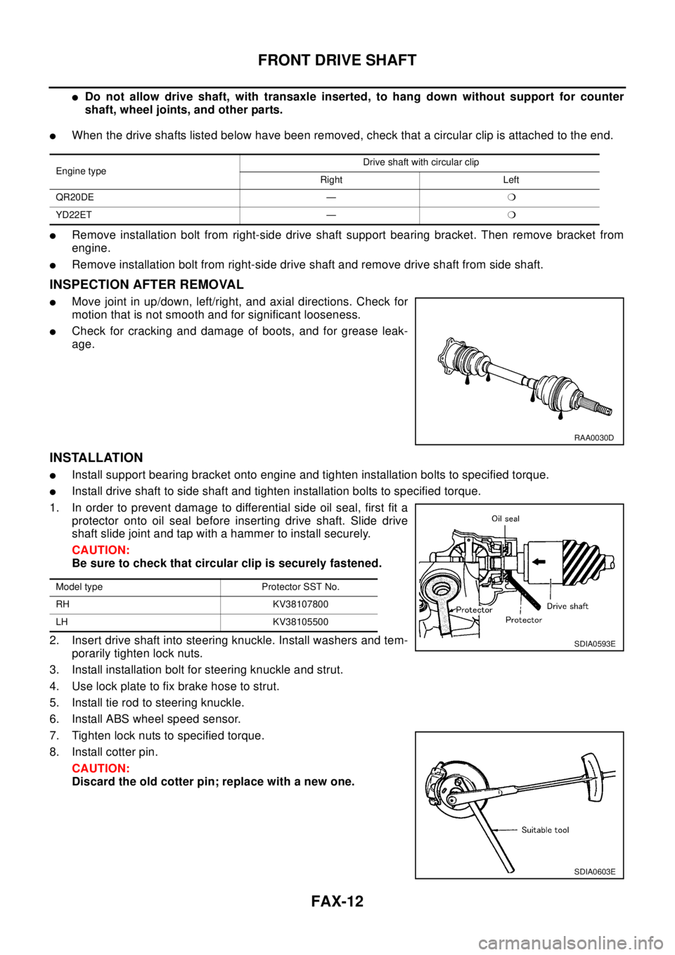
lMove joint in up/down, left/right, and axial directions. Check for
motion that is not smooth and for significant looseness.
lCheck for cracking and damage of boots, and for grease leak-
age.
INSTALLATION
lInstall support bearing bracket onto engine and tighten installation bolts to specified torque.
lInstall drive shaft to side shaft and tighten installation bolts to specified torque.
1. In order to prevent damage to differential side oil seal, first fit a
protector onto oil seal before inserting drive shaft. Slide drive
shaft slide joint and tap with a hammer to install securely.
CAUTION:
Be sure to check that circular clip is securely fastened.
2. Insert drive shaft into steering knuckle. Install washers and tem-
porarily tighten lock nuts.
3. Install installation bolt for steering knuckle and strut.
4. Use lock plate to fix brake hose to strut.
5. Install tie rod to steering knuckle.
6. Install ABS wheel speed sensor.
7. Tighten lock nuts to specified torque.
8. Install cotter pin.
CAUTION:
Discard the old cotter pin; replace with a new one.
Engine typeDrive shaft with circular clip
Right Left
QR20DE —m
YD22ET —m
RAA0030D
Model type Protector SST No.
RH KV38107800
LH KV38105500
SDIA0593E
SDIA0603E
Page 2223 of 3066
![NISSAN X-TRAIL 2003 Electronic Repair Manual FL-8
[QR20DE]
FUEL LEVEL SENSOR UNIT, FUEL FILTER AND FUEL PUMP ASSEMBLY
2. Disconnect fuel pump harness connector.
3. Separate the fuel filter and fuel level sensor unit.
a. Fit a used O-ring into sp NISSAN X-TRAIL 2003 Electronic Repair Manual FL-8
[QR20DE]
FUEL LEVEL SENSOR UNIT, FUEL FILTER AND FUEL PUMP ASSEMBLY
2. Disconnect fuel pump harness connector.
3. Separate the fuel filter and fuel level sensor unit.
a. Fit a used O-ring into sp](/manual-img/5/57402/w960_57402-2222.png)
FL-8
[QR20DE]
FUEL LEVEL SENSOR UNIT, FUEL FILTER AND FUEL PUMP ASSEMBLY
2. Disconnect fuel pump harness connector.
3. Separate the fuel filter and fuel level sensor unit.
a. Fit a used O-ring into space between fuel level sensor unit and
fuel filter. Undo catches and separate fuel level sensor unit and
fuel filter.
lFor reference when reassembling, put a mating mark on outer
edges of fuel level sensor unit and fuel filter with some means
which cannot be erased by fuel.
b. Insert blade end screwdriver to the gap between the fuel filter
and fuel level sensor unit to separate them.
CAUTION:
Put cloth or similar one on the edge of screwdriver not to
damage the inserted portion.
4. Remove pressure regulator from fuel filter.
a. Open and remove the clip.
b. Pull the pressure regulator straight out during removal.
CAUTION:
lAvoid impacts such as falling during removal.
lDo not disassemble or adjust.
ASSEMBLY
Install in the reverse order of removal paying attention to the following.
lInstall the fuel filter and fuel pump with the tabs aligned, Make sure a click sound of secure engagement
is heard.
lSecurely connect the harness connector of the fuel pump.
lInstall the pressure regulator O-ring as follows.
CAUTION:
lWhen replacing, always use a new O-ring.
lHandle it with bare hands. (Do not use gloves.)
lVisually check the O-ring, mounting parts and mating parts for foreign materials and flaws.
lBefore installing, apply new engine oil.
lTo avid damage, do not apply an excessive force (pulling or starching).
lInstall the pressure regulator as follows.
1. Insert the clip to the groove of the regulator.
2. With the clip installed, insert the regulator straight by matching
the fuel filter protrusion and the clip notch.
3. Make sure that the fuel filter protrusion and clip notch are
securely engaged.
PBIC0243E
PBIC0244E
PBIC0245E
Page 2241 of 3066

FSU-2
PRECAUTIONS
PRECAUTIONS
PFP:00001
CautionEES0006Z
lWhen installing rubber bushings, final tightening must be carried out under unladen conditions with tires
on flat, level ground. Oil will shorten the life of rubber bushings. Be sure to wipe off any spilled oil.
l“Unladen condition” means that fuel, coolant and lubricant are full and ready for drive. However, spare tire,
jack, and hand tools should be unloaded.
lAfter installing the removed suspension parts, always check wheel alignment and adjust if necessary.
lReplace the caulking nut with a new one. Install a new nut without wiping the oil off before tightening.
Precautions for Brake SystemEES000JA
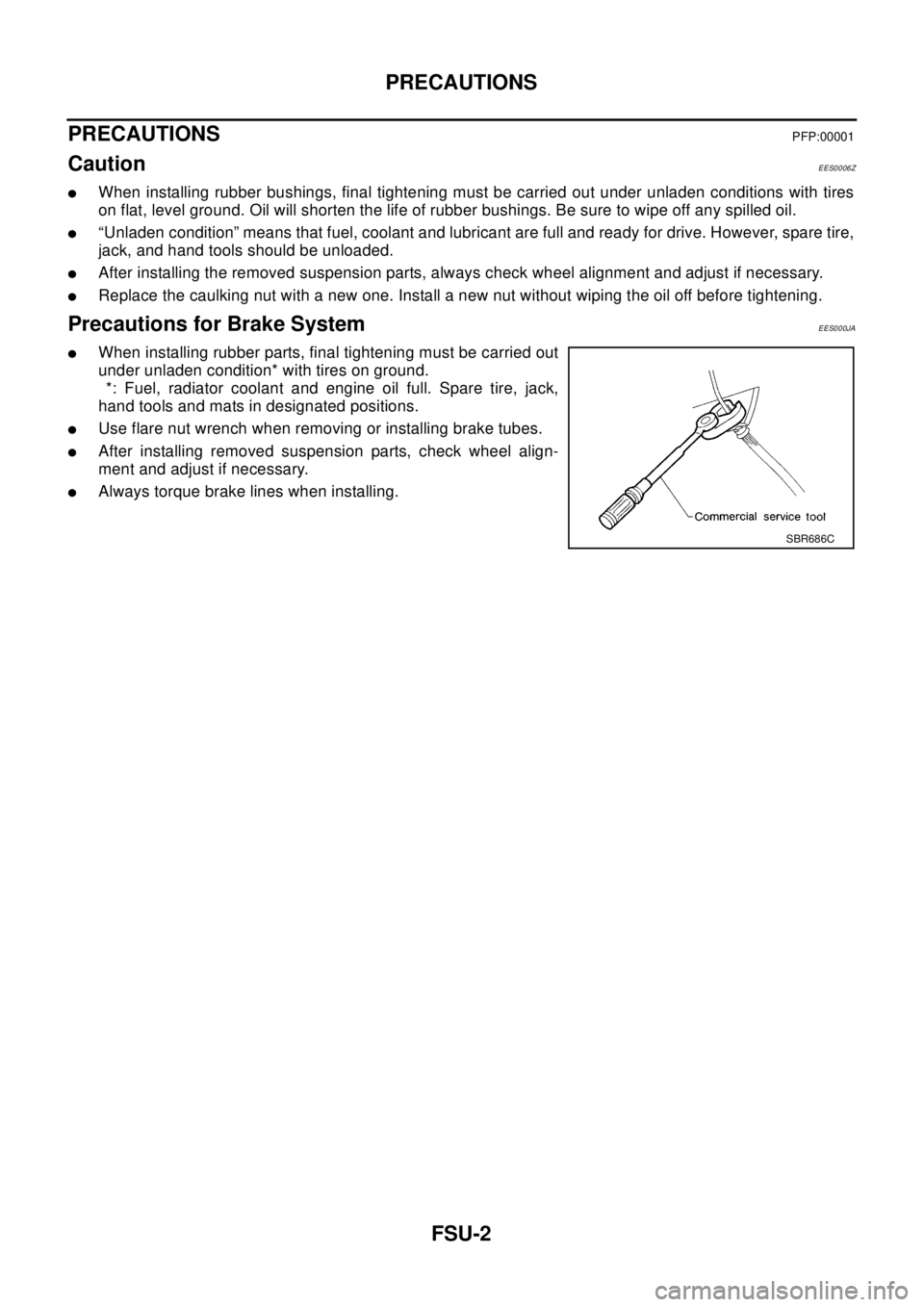
lWhen installing rubber parts, final tightening must be carried out
under unladen condition* with tires on ground.
*: Fuel, radiator coolant and engine oil full. Spare tire, jack,
hand tools and mats in designated positions.
lUse flare nut wrench when removing or installing brake tubes.
lAfter installing removed suspension parts, check wheel align-
ment and adjust if necessary.
lAlways torque brake lines when installing.
SBR686C