2003 NISSAN X-TRAIL brakes
[x] Cancel search: brakesPage 856 of 3066

BR-22
FRONT DISC BRAKE
Pad Replacement
EFS000CI
REMOVAL
CAUTION:
When replacing brake pads, always replace inner shims, outer shims, and shim covers as a set.
1. Remove master cylinder reservoir tank cap.
2. Remove lower sliding pin bolt.
3. Hang cylinder body with a wire, and remove pads, pad retainers,
shims and pad return springs.
INSTALLATION
1. Apply brake grease on back of the pad and both sides of the shim. Install inner shim and inner shim cover
to inner pad, outer shim to outer pad.
2. Apply brake grease on the pad retainer pad contact surface. Install pad retainers, pads and pad return
springs to the torque member.
3. Connect cylinder body to the torque member.
CAUTION:
When replacing pads with new ones, press piston in until the pads can be installed. Carefully mon-
itor brake master cylinder reservoir fluid level. Brake fluid will return, raising master cylinder res-
ervoir tank fluid level.
4. Insert lower sliding pin bolt and tighten to the specified torque.
5. Check brakes for drag.
Caliper Removal and InstallationEFS000CJ
REMOVAL
1. Connect a vinyl tube to the air bleeder.
2. Drain brake fluid gradually from air bleeder while depressing brake pedal.
SBR433D
SBR932C
Page 862 of 3066
BR-28
REAR DISC BRAKE
Pad Replacement
EFS0017Z
REMOVAL
CAUTION:
When replacing brake pads, always replace inner shims, outer shims, and shim covers as a set.
1. Remove master cylinder reservoir tank cap.
2. Remove lower sliding pin bolt.
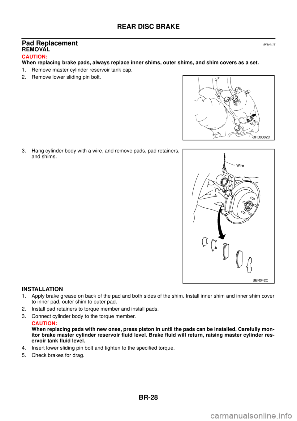
3. Hang cylinder body with a wire, and remove pads, pad retainers,
and shims.
INSTALLATION
1. Apply brake grease on back of the pad and both sides of the shim. Install inner shim and inner shim cover
to inner pad, outer shim to outer pad.
2. Install pad retainers to torque member and install pads.
3. Connect cylinder body to the torque member.
CAUTION:
When replacing pads with new ones, press piston in until the pads can be installed. Carefully mon-
itor brake master cylinder reservoir fluid level. Brake fluid will return, raising master cylinder res-
ervoir tank fluid level.
4. Insert lower sliding pin bolt and tighten to the specified torque.
5. Check brakes for drag.
BRB0302D
SBR042C
Page 869 of 3066

BRC-1
BRAKE CONTROL SYSTEM
F BRAKES
CONTENTS
C
D
E
G
H
I
J
K
L
M
SECTION
A
B
BRC
BRAKE CONTROL SYSTEM
4WD/ABS
PRECAUTIONS .......................................................... 4
Precautions for brake system ................................... 4
Precautions for brake control ................................... 4
PREPARATION ........................................................... 5
Special Service Tools ............................................... 5
ALL MODE 4X4 SYSTEM .......................................... 6
System Description .................................................. 6
ABS FUNCTION ................................................... 6
4WD FUNCTION ................................................... 6
Control System Diagram .......................................... 6
TROUBLE DIAGNOSIS .............................................. 7
Fail-safe Function ..................................................... 7
How to Proceed with Trouble Diagnosis .................. 7
BASIC CONCEPT ................................................. 7
DIAGNOSIS FLOW ............................................... 8
ASKING COMPLAINTS ........................................ 9
TROUBLE DIAGNOSIS SHEET - EXAMPLE ....... 9
Component Parts Location ..................................... 10
Schematic ...............................................................11
Wiring Diagram — ABS — ..................................... 12
Trouble Diagnosis Chart by Symptom .................... 18
4WD/ABS Control Unit Input/Output Signal Stan-
dard ........................................................................ 19
4WD/ABS CONTROL UINT CONNECTOR TER-
MINAL ARRANGEMENT .................................... 19
REFERENCE STANDARD TABLE ..................... 19
CONSULT-II Functions ........................................... 23
CONSULT-II FUNCTION APPLICATION TABLE... 23
SELF-DIAGNOSIS .............................................. 24
DATA MONITOR ................................................. 26
ACTIVE TEST ..................................................... 29
Component Inspection ........................................... 30
ABS ACTUATOR ................................................ 30
4WD SOLENOID VALVE .................................... 32
Basic Inspection ..................................................... 32
BASIC INSPECTION 1 BRAKE FLUID LEVEL
AND LEAKAGE INSPECTION ............................ 32
BASIC INSPECTION 2 INSPECTION FOR
LOOSE POWER SUPPLY TERMINAL ............... 32BASIC INSPECTION 3 ABS/4WD WARNING
LAMP INSPECTION ............................................ 32
Wheel Speed Sensor System ................................. 32
INSPECTION PROCEDURE .............................. 32
Control Module Power Supply System ................... 34
INSPECTION PROCEDURE .............................. 34
G -Sensor System (4WD models) .......................... 34
INSPECTION PROCEDURE .............................. 34
4WD SOLENOID, ACTUATOR RELAY SYSTEM... 35
4WD MODE SWITCH SYSTEM ............................. 37
Trouble Diagnoses for Symptoms .......................... 38
4WD INDICATOR LAMP DOES NOT COME ON
FORAPPROXIMATELY1SECONDWHENTHE
IGNITION SWITCH IS TURNED TO ON ............. 38
4WD WARNING LAMP DOES NOT ILLUMINATE
WITH IGNITION ON ............................................ 39
4WD WARNING LAMP DOES NOT GO OUT
SEVERAL SECONDS AFTER ENGINE
STARTED.(4WD MODE INDICATOR LAMP
GOES OUT) ........................................................ 39
HEAVY TIGHT-CORNER BRAKING SYMPTOM
OCCURS WHEN THE VEHICLE IS DRIVEN IN
AUTO MODE AND THE STEERING WHEEL IS
TURNED FULLY TO EITHER SIDE AFTER THE
ENGINE IS STARTED ......................................... 39
4WD MODES CANNOT BE SWITCHED AFTER
ENGINE IS STARTED ......................................... 41
WHILE DRIVING, 4WD WARNING LAMP
FLASHES RAPIDLY. (WHEN IT FLASHERSFOR
APPROX. ONE MINUTE, THEN DOES NOT
ILLUMINATE.) ..................................................... 41
WHILE DRIVING, 4WD WARNING LAMP
FLASHES SLOWLY. (WHEN IT CONTINUES TO
ILLUMINATE UNTIL ENGINE TURNS OFF.) ...... 41
VEHICLE DOES NOT ENTER 4WD MODE
EVEN THOUGH 4WD WARNING LAMP IS OFF.... 41
TIGHT-CONER BRAKING SYMPTOM OCCURS
WHEN THE VEHICLE IS STARTED IN AUTO
WARNING LAMP REMAIN OFF). ....................... 42
4WD ACTUATOR RELAY (4WD SOLENOID
Page 919 of 3066
![NISSAN X-TRAIL 2003 Electronic Repair Manual ACTUATOR
BRC-51
[4WD/ABS]
C
D
E
G
H
I
J
K
L
MA
B
BRC
ACTUATORPFP:47600
Removal and InstallationEFS001CO
REMOVAL
Be careful of the following.
CAUTION:
lBefore servicing, disconnect battery terminals.
l](/manual-img/5/57402/w960_57402-918.png "NISSAN X-TRAIL 2003 Electronic Repair Manual ACTUATOR
BRC-51
[4WD/ABS]
C
D
E
G
H
I
J
K
L
MA
B
BRC
ACTUATORPFP:47600
Removal and InstallationEFS001CO
REMOVAL
Be careful of the following.
CAUTION:
lBefore servicing, disconnect battery terminals.
l")
ACTUATOR
BRC-51
[4WD/ABS]
C
D
E
G
H
I
J
K
L
MA
B
BRC
ACTUATORPFP:47600
Removal and InstallationEFS001CO
REMOVAL
Be careful of the following.
CAUTION:
lBefore servicing, disconnect battery terminals.
lTo remove brake tube, use a flare nut wrench to prevent flare nuts and brake tube from being dam-
aged. To install, use a flare nut torque wrench and tighten to the specified torque.
INSTALLATION
Be careful of the following.
lTighten mounting bolts and nuts to the specified torque.
lAfter the work, bleed the brakes. Refer toBR-10, "Bleeding Brake System".
SFIA0360E
Page 920 of 3066
![NISSAN X-TRAIL 2003 Electronic Repair Manual BRC-52
[ESP/TCS/ABS]
PRECAUTIONS
[ESP/TCS/ABS]PRECAUTIONSPFP:00001
Precautions for Supplemental Restraint System (SRS) “AIR BAG” and “SEAT
BELT PRE-TENSIONER”
EFS0019N
The Supplemental Restrai](/manual-img/5/57402/w960_57402-919.png "NISSAN X-TRAIL 2003 Electronic Repair Manual BRC-52
[ESP/TCS/ABS]
PRECAUTIONS
[ESP/TCS/ABS]PRECAUTIONSPFP:00001
Precautions for Supplemental Restraint System (SRS) “AIR BAG” and “SEAT
BELT PRE-TENSIONER”
EFS0019N
The Supplemental Restrai")
BRC-52
[ESP/TCS/ABS]
PRECAUTIONS
[ESP/TCS/ABS]PRECAUTIONSPFP:00001
Precautions for Supplemental Restraint System (SRS) “AIR BAG” and “SEAT
BELT PRE-TENSIONER”
EFS0019N
The Supplemental Restraint System such as “AIR BAG” and “SEAT BELT PRE-TENSIONER”, used along
with a front seat belt, helps to reduce the risk or severity of injury to the driver and front passenger for certain
types of collision. Information necessary to service the system safely is included in the SRS and SB section of
this Service Manual.
WAR NIN G:
lTo avoid rendering the SRS inoperative, which could increase the risk of personal injury or death
in the event of a collision which would result in air bag inflation, all maintenance must be per-
formed by an authorized NISSAN/INFINITI dealer.
lImproper maintenance, including incorrect removal and installation of the SRS, can lead to per-
sonal injury caused by unintentional activation of the system. For removal of Spiral Cable and Air
Bag Module, see the SRS section.
lDo not use electrical test equipment on any circuit related to the SRS unless instructed to in this
Service Manual. SRS wiring harnesses can be identified by yellow harness connector.
Precautions for Brake SystemEFS0019O
lRecommended fluid is brake fluid “DOT 3” or “DOT 4”.
lNever reuse drained brake fluid.
lBe careful not to splash brake fluid on painted areas; it may cause paint damage. If brake fluid is splashed
on painted areas, wash it away with water immediately.
lNever use mineral oils such as gasoline or kerosene. They will ruin rubber parts of hydraulic system.
lUse flare nut wrench when removing and installing brake tubes.
lAlways torque brake lines when installing.
lBefore working, turn the ignition switch OFF and disconnect the
connectors for the ESP/TCS/ABS actuator and control unit or
the battery terminals.
lBurnish the brake contact surfaces after refinishing or replacing
drums or rotors, after replacing pads or linings, or if a soft pedal
occurs at very low mileage. Refer toBR-10, "
Brake Burnishing
Procedure".
WAR NIN G:
Clean brakes with a vacuum dust collector to minimize risk
of health hazard from powder caused by friction.
Precautions for Brake ControlEFS0019P
lDuring the EPS/TCS/ABS operation, the brake pedal vibrates lightly and its mechanical noise may be
heard. This is a normal condition.
lJust after starting the vehicle after ignition switch ON, the brake pedal may vibrate or the motor operating
noise may be heard from the engine compartment. This is a normal status of the operation check.
lThe stopping distance may be longer than that of vehicles without ABS when the vehicle drives on rough,
gravel, or snowy (fresh deep snow) road.
lIf a malfunction is indicated by the ABS warning lamp, or other warning lamps, collect the necessary infor-
mation from the customer (what symptoms are present under what conditions) and find out the possible
causes before starting the service. Besides the electrical system inspection, check the booster operation,
brake fluid level, and oil leaks.
lIf the tire size and type are used in a improper combination, or the brake pads are not NISSAN genuine
parts, the stopping distance or steering stability may deteriorate.
lIf there is a radio, antenna, or antenna lead-in wire (including wiring) near the control unit, the ESP/TCS/
ABS function may have a malfunction or error.
lIf aftermarket parts (e.g. Car stereo equipment, CD player) have been installed, check the electrical har-
nesses for pinches, open, and improper wiring.
SBR686C
Page 1016 of 3066
![NISSAN X-TRAIL 2003 Electronic Repair Manual CO-6
[QR20DE]
OVERHEATING CAUSE ANALYSIS
Except cool-
ing system
parts mal-
function— OverloadonengineAbusive drivingHigh engine rpm under no
load
Driving in low gear for
extended time
Driving at ex](/manual-img/5/57402/w960_57402-1015.png "NISSAN X-TRAIL 2003 Electronic Repair Manual CO-6
[QR20DE]
OVERHEATING CAUSE ANALYSIS
Except cool-
ing system
parts mal-
function— OverloadonengineAbusive drivingHigh engine rpm under no
load
Driving in low gear for
extended time
Driving at ex")
CO-6
[QR20DE]
OVERHEATING CAUSE ANALYSIS
Except cool-
ing system
parts mal-
function— OverloadonengineAbusive drivingHigh engine rpm under no
load
Driving in low gear for
extended time
Driving at extremely high
speed
Powertrain system mal-
function
— Installed improper size
wheels and tires
Dragging brakes
Improper ignition timing
Blocked or restricted air
flowBlocked bumper —
— Blocked radiator grilleInstalled car brassiere
Mud contamination or
paper clogging
Blocked radiator —
Blocked condenser
—
Installed large fog lamp Symptom Check items
Page 1037 of 3066
![NISSAN X-TRAIL 2003 Electronic Repair Manual OVERHEATING CAUSE ANALYSIS
CO-27
[YD22DDTi]
C
D
E
F
G
H
I
J
K
L
MA
CO
Except cool-
ing system
parts mal-
function— Overload on engineAbusive drivingHigh engine rpm under no
load
Driving in low gear](/manual-img/5/57402/w960_57402-1036.png "NISSAN X-TRAIL 2003 Electronic Repair Manual OVERHEATING CAUSE ANALYSIS
CO-27
[YD22DDTi]
C
D
E
F
G
H
I
J
K
L
MA
CO
Except cool-
ing system
parts mal-
function— Overload on engineAbusive drivingHigh engine rpm under no
load
Driving in low gear")
OVERHEATING CAUSE ANALYSIS
CO-27
[YD22DDTi]
C
D
E
F
G
H
I
J
K
L
MA
CO
Except cool-
ing system
parts mal-
function— Overload on engineAbusive drivingHigh engine rpm under no
load
Driving in low gear for
extended time
Driving at extremely high
speed
Powertrain system mal-
function
— Installed improper size
wheels and tires
Dragging brakes
Improper ignition timing
Blocked or restricted air
flowBlocked bumper —
— Blocked radiator grilleInstalled car brassiere
Mud contamination or
paper clogging
Blocked radiator —
Blocked condenser
—
Installed large fog lamp Symptom Check items
Page 2243 of 3066

FSU-4
NOISE, VIBRATION, AND HARSHNESS (NVH) TROUBLESHOOTING
NOISE, VIBRATION, AND HARSHNESS (NVH) TROUBLESHOOTING
PFP:00003
NVH Troubleshooting ChartEES000ID
Use the chart below to help you find the cause of the symptom. If necessary, repair or replace these parts.
´: ApplicableReference page
Refer toFSU-5Refer toFSU-8
—
—
—
Refer toFSU-5
Refer toFSU-6Refer toFSU-11NVH in PR section
NVH in RFD section.
NVHinRAXandRSUsection.
NVH in WT section.
NVH in WT section.
NVH in RAX section.
NVH in BR section.
NVH in PS section.
Possible cause and SUSPECTED PARTS
Improper installation, looseness
Shock absorber deformation, damage or deflection
Bushing or mounting deterioration
Parts interference
Spring fatigue
Suspension looseness
Incorrect wheel alignment
Stabilizer bar fatigue
PROPELLER SHAFT
DIFFERENTIAL
REAR AXLE AND REAR SUSPENSION
TIRES
ROAD WEEL
DRIVE SHAFT
BRAKES
STEERING
Symptom FRONT SUSPENSIONNoise´´´´´ ´ ´´´ ´´´´´
Shake´´´´ ´ ´ ´ ´´´´´
Vibration´´´´´ ´ ´´ ´ ´
Shimmy´´´´ ´ ´´´ ´´
Judder´´´ ´´´ ´´
Poor quality ride or han-
dling´´´´´ ´´ ´ ´´´