Page 662 of 3066
ATC-84
TROUBLE DIAGNOSIS
PERFORMANCE CHART
Test Condition
Testing must be performed as follows:
*1ATC-129, "Removal and Installation
for Compressor Clutch"
*2 Trouble diagnoses for blower motor
AT C - 6 7 , "
Blower Motor Circuit"
*3 Belt tension,EM-13QR engine ;EM-
11 0YD engine
Page 670 of 3066
ATC-92
TROUBLE DIAGNOSIS
Self-diagnosis
EJS001H9
Symptom: Self-diagnosis can not be performed.
INSPECTION FLOW
Memory FunctionEJS001HA
Symptom: Memory function does not operate.
*1ATC-129, "Removal and Installation
for Compressor Clutch"
*3AT C - 2 1 , "Maintenance of Lubricant
Quantity in Compressor"
*5EM-13, "Checking Drive Belts"QR
engine;EM-110, "
Checking Drive
Belts"YD engine
*2ATC-132, "
Inspection"*4 Operational checkAT C - 5 1
*1 Main power supply and body ground
circuit.PG-3*2 Ambient sensor circuit.AT C - 9 3*3 In-vehicle sensor circuit .AT C - 9 5
*4 sunload sensor circuit.AT C - 9 8*5 Intake sensor circuit.AT C - 1 0 1*6 Air mix door motor.AT C - 6 1
*7 Operational check.AT C - 5 1*8 Symptom table.AT C -3 0*9 Operational checkAT C - 5 1
RJIA0551E
Page 705 of 3066
REFRIGERANT LINES
ATC-127
C
D
E
F
G
H
I
K
L
MA
B
AT C
With Diesel Engine
1. Using recycling and recovery equipment (for HFC-134a), discharge the refrigerant.
2. Remove the engine under cover.
3. Remove the compressor-alternator belt.
Refer to,EM-13, "
Removal and Installation"QR engine;E M - 111 , "Removal and Installation"YD engine.
4. Remove the mounting nuts (bolts) from the high-pressure flexi-
ble hose and low-pressure flexible hose.
CAUTION:
Cap or wrap the joint of the pipe with suitable material such
as vinyl tape to avoid the entry of air.
5. Disconnect the compressor connector.
RHA667H
RJIA0073E
RJIA0579E
Page 722 of 3066
ATC-144
REFRIGERANT LINES
LUBRICANT
REFRIGERANT
ENGINE IDLING SPEED
Refer toATC-144, "ENGINE IDLING SPEED".
BELT TENSION
Refer to,EM-13, "Tension Adjustment"QR engine;EM-110, "Tension Adjustment"YD engine.
Displacement
cm3 (cu. in)/revMax. 184 (11.228)
110 (6.71)
Min. 14.5 (0.885)
Cylinder bore´stroke
mm (in)37 (1.46)´[2.3 - 28.6 (0.091 - 1.126)] -
Direction of rotation Clockwise (viewed from drive end)
Drive beltPoly V
ModelWith gasoline engine With diesel engine
CALSONIC KANSEI make V-6 ZEXEL VALEO make DKV-11G
Name Nissan A/C System Oil Type S Nissan A/C System Oil Type R
Part number KLH00-PAGS0 KLH00-PAGR0
Capacity
ml (lmp fl oz)Total in system 180 (6.3)
Compressor (Service part) charging
amount180 (6.3)
Ty p eHFC-134a (R-134a)
Capacity
kg (lb)0.50 (1.10)
Page 723 of 3066

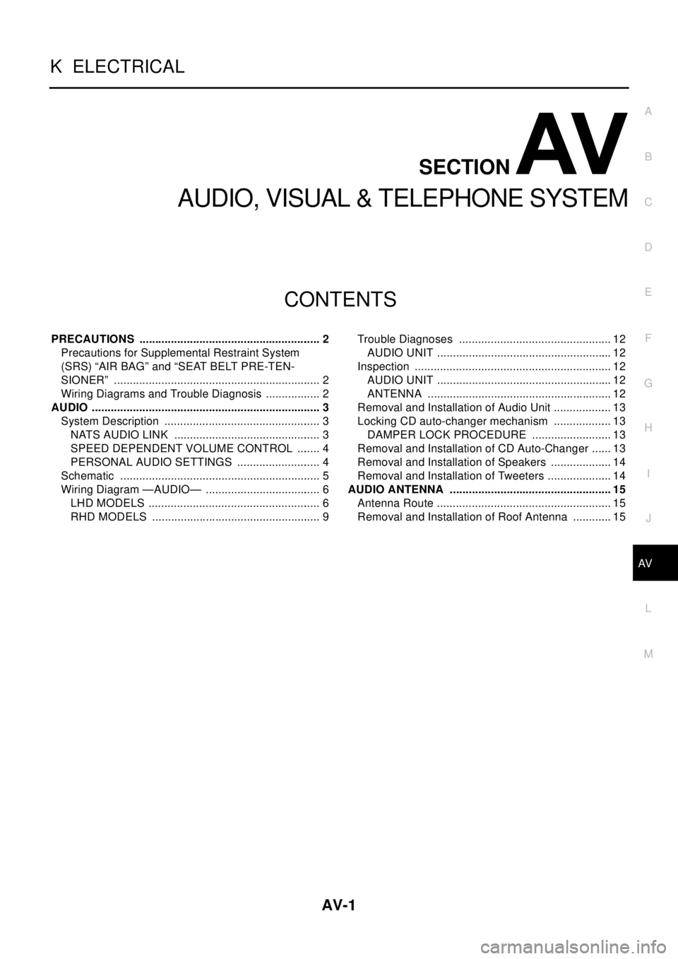
AV-1
AUDIO, VISUAL & TELEPHONE SYSTEM
K ELECTRICAL
CONTENTS
C
D
E
F
G
H
I
J
L
M
SECTION
A
B
AV
AUDIO, VISUAL & TELEPHONE SYSTEM
PRECAUTIONS .......................................................... 2
Precautions for Supplemental Restraint System
(SRS) “AIR BAG” and “SEAT BELT PRE-TEN-
SIONER” .................................................................. 2
Wiring Diagrams and Trouble Diagnosis .................. 2
AUDIO ......................................................................... 3
System Description .................................................. 3
NATS AUDIO LINK ............................................... 3
SPEED DEPENDENT VOLUME CONTROL ........ 4
PERSONAL AUDIO SETTINGS ........................... 4
Schematic ................................................................ 5
Wiring Diagram —AUDIO— ..................................... 6
LHD MODELS ....................................................... 6
RHD MODELS ...................................................... 9Trouble Diagnoses ................................................. 12
AUDIO UNIT ........................................................ 12
Inspection ............................................................... 12
AUDIO UNIT ........................................................ 12
ANTENNA ........................................................... 12
Removal and Installation of Audio Unit ................... 13
Locking CD auto-changer mechanism ................... 13
DAMPER LOCK PROCEDURE .......................... 13
Removal and Installation of CD Auto-Changer ....... 13
Removal and Installation of Speakers .................... 14
Removal and Installation of Tweeters ..................... 14
AUDIO ANTENNA .................................................... 15
Antenna Route ........................................................ 15
Removal and Installation of Roof Antenna ............. 15
Page 724 of 3066

AV-2
PRECAUTIONS
PRECAUTIONS
PFP:00011
Precautions for Supplemental Restraint System (SRS) “AIR BAG” and “SEAT
BELT PRE-TENSIONER”
EKS0036C
The Supplemental Restraint System such as “AIR BAG” and “SEAT BELT PRE-TENSIONER”, used along
with a front seat belt, helps to reduce the risk or severity of injury to the driver and front passenger for certain
types of collision. Information necessary to service the system safely is included in the SRS and SB section of
this Service Manual.
WAR NIN G:
lTo avoid rendering the SRS inoperative, which could increase the risk of personal injury or death
in the event of a collision which would result in air bag inflation, all maintenance must be per-
formed by an authorized NISSAN/INFINITI dealer.
lImproper maintenance, including incorrect removal and installation of the SRS, can lead to per-
sonal injury caused by unintentional activation of the system. For removal of Spiral Cable and Air
Bag Module, see the SRS section.
lDo not use electrical test equipment on any circuit related to the SRS unless instructed to in this
Service Manual. SRS wiring harnesses can be identified by yellow harness connectors.
Wiring Diagrams and Trouble DiagnosisEKS0036D
When you read wiring diagrams, refer to the followings:
lRefer toGI-14, "How to Read Wiring Diagrams"in GI section
lRefer toPG-2, "POWER SUPPLY ROUTING"for power distribution circuit in PG section
When you perform trouble diagnosis, refer to the followings:
lRefer toGI-11, "HOW TO FOLLOW TEST GROUPS IN TROUBLE DIAGNOSES"in PG section
lRefer toGI-24, "How to Perform Efficient Diagnosis for an Electrical Incident"in PG section
Page 739 of 3066
BCS-1
BODY CONTROL SYSTEM
K ELECTRICAL
CONTENTS
C
D
E
F
G
H
I
J
L
M
SECTION
A
B
BCS
BODY CONTROL SYSTEM
PRECAUTIONS .......................................................... 2
Precautions for Supplemental Restraint System
(SRS) “AIR BAG” and “SEAT BELT PRE-TEN-
SIONER” .................................................................. 2
Wiring Diagrams and Trouble Diagnosis .................. 2
TIME CONTROL UNIT ............................................... 3Description ................................................................ 3
OUTLINE ............................................................... 3
INPUT/OUTPUT .................................................... 3
Schematic ................................................................. 4
Time Control Unit Inspection Table ........................... 5
Page 740 of 3066

BCS-2
PRECAUTIONS
PRECAUTIONS
PFP:00011
Precautions for Supplemental Restraint System (SRS) “AIR BAG” and “SEAT
BELT PRE-TENSIONER”
EKS00369
The Supplemental Restraint System such as “AIR BAG” and “SEAT BELT PRE-TENSIONER”, used along
with a front seat belt, helps to reduce the risk or severity of injury to the driver and front passenger for certain
types of collision. Information necessary to service the system safely is included in the SRS and SB section of
this Service Manual.
WAR NIN G:
lTo avoid rendering the SRS inoperative, which could increase the risk of personal injury or death
in the event of a collision which would result in air bag inflation, all maintenance must be per-
formed by an authorized NISSAN/INFINITI dealer.
lImproper maintenance, including incorrect removal and installation of the SRS, can lead to per-
sonal injury caused by unintentional activation of the system. For removal of Spiral Cable and Air
Bag Module, see the SRS section.
lDo not use electrical test equipment on any circuit related to the SRS unless instructed to in this
Service Manual. SRS wiring harnesses can be identified by yellow harness connectors.
Wiring Diagrams and Trouble DiagnosisEKS0036B
When you read wiring diagrams, refer to the followings:
lRefer toGI-14, "How to Read Wiring Diagrams"in GI section.
lRefer toPG-2, "POWER SUPPLY ROUTING"for power distribution circuit in PG section.
When you perform trouble diagnosis, refer to the followings:
lRefer toGI-11, "HOW TO FOLLOW TEST GROUPS IN TROUBLE DIAGNOSES"in GI section.
lRefer toGI-24, "How to Perform Efficient Diagnosis for an Electrical Incident"in GI section.