2003 NISSAN X-TRAIL brake sensor
[x] Cancel search: brake sensorPage 2365 of 3066
IDX-8
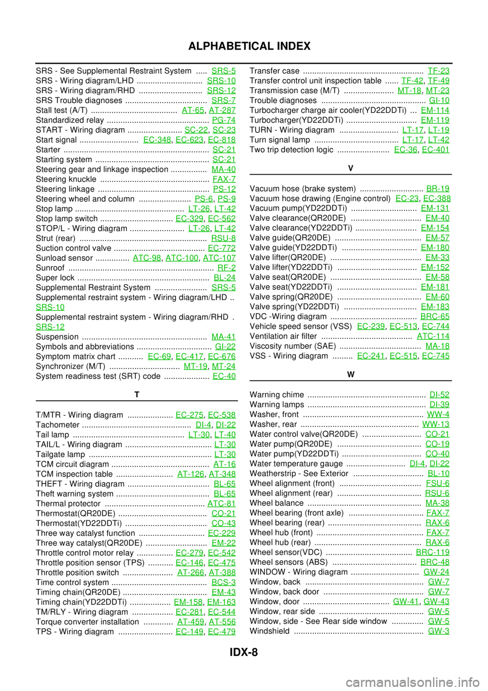
ALPHABETICAL INDEX
SRS - See Supplemental Restraint System .....SRS-5
SRS - Wiring diagram/LHD .............................SRS-10
SRS - Wiring diagram/RHD ............................SRS-12
SRS Trouble diagnoses ....................................SRS-7
Stall test (A/T) ......................................AT-65,AT-287
Standardized relay .............................................PG-74
START - Wiring diagram ........................SC-22,SC-23
Start signal ..........................EC-348,EC-623,EC-818
Starter ................................................................SC-21
Starting system ..................................................SC-21
Steering gear and linkage inspection ................MA-40
Steering knuckle ................................................FAX-7
Steering linkage .................................................PS-12
Steering wheel and column .......................PS-6,PS-9
Stop lamp ................................................LT-26,LT-42
Stop lamp switch ................................EC-329,EC-562
STOP/L - Wiring diagram ........................LT-26,LT-42
Strut (rear) ........................................................RSU-8
Suction control valve ........................................EC-772
Sunload sensor ...............ATC-98,ATC-100,ATC-107
Sunroof ................................................................RF-2
Super lock ..........................................................BL-24
Supplemental Restraint System .......................SRS-5
Supplemental restraint system - Wiring diagram/LHD ..
SRS-10
Supplemental restraint system - Wiring diagram/RHD .
SRS-12
Suspension .......................................................MA-41
Symbols and abbreviations .................................GI-22
Symptom matrix chart ...........EC-69,EC-417,EC-676
Synchronizer (M/T) ...............................MT-19,MT-24
System readiness test (SRT) code ....................EC-40
T
T/MTR - Wiring diagram ....................EC-275
,EC-538
Tachometer ................................................DI-4,DI-22
Tail lamp .................................................LT-30,LT-40
TAIL/L - Wiring diagram ......................................LT-30
Tailgate lamp ......................................................LT-30
TCM circuit diagram ...........................................AT-16
TCM inspection table .........................AT-126,AT-348
THEFT - Wiring diagram ....................................BL-65
Theft warning system .........................................BL-65
Thermal protector ............................................ATC-81
Thermostat(QR20DE) .......................................CO-21
Thermostat(YD22DDTi) ....................................CO-43
Three way catalyst function .............................EC-229
Three way catalyst(QR20DE) ...........................EM-22
Throttle control motor relay ................EC-279,EC-542
Throttle position sensor (TPS) ...........EC-146,EC-475
Throttle position switch ......................AT-266,AT-388
Time control system ..........................................BCS-3
Timing chain(QR20DE) .....................................EM-43
Timing chain(YD22DDTi) ..................EM-158,EM-163
TM/RLY - Wiring diagram ..................EC-281,EC-544
Torque converter installation .............AT-459,AT-556
TPS - Wiring diagram ........................EC-149,EC-479
Transfer case .....................................................TF-23
Transfer control unit inspection table ......TF-42,TF-49
Transmission case (M/T) ......................MT-18,MT-23
Trouble diagnoses ..............................................GI-10
Turbocharger charge air cooler(YD22DDTi) ...EM-114
Turbocharger(YD22DDTi) ...............................EM-119
TURN - Wiring diagram ..........................LT-17,LT-19
Turn signal lamp .....................................LT-17,LT-42
Two trip detection logic .......................EC-36,EC-401
V
Vacuum hose (brake system) ............................BR-19
Vacuum hose drawing (Engine control)EC-23,EC-388
Vacuum pump(YD22DDTi) .............................EM-131
Valve clearance(QR20DE) ...............................EM-40
Valve clearance(YD22DDTi) ...........................EM-154
Valve guide(QR20DE) ......................................EM-57
Valve guide(YD22DDTi) .................................EM-180
Valve lifter(QR20DE) ........................................EM-33
Valve lifter(YD22DDTi) ...................................EM-152
Valve seat(QR20DE) ........................................EM-58
Valve seat(YD22DDTi) ...................................EM-181
Valve spring(QR20DE) .....................................EM-60
Valve spring(YD22DDTi) ................................EM-183
VDC -Wiring diagram ......................................BRC-65
Vehicle speed sensor (VSS)EC-239,EC-513,EC-744
Ventilation air filter ........................................ATC-114
Viscosity number (SAE) ....................................MA-18
VSS - Wiring diagram .........EC-241,EC-515,EC-745
W
Warning chime ....................................................DI-52
Warning lamps ....................................................DI-39
Washer, front .....................................................WW-4
Washer, rear ....................................................WW-13
Water control valve(QR20DE) ..........................CO-21
Water pump(QR20DE) .....................................CO-19
Water pump(YD22DDTi) ...................................CO-40
Water temperature gauge ..........................DI-4,DI-22
Weatherstrip - See Exterior ...............................BL-10
Wheel alignment (front) ....................................FSU-6
Wheel alignment (rear) .....................................RSU-6
Wheel balance ..................................................MA-38
Wheel bearing (front axle) .................................FAX-7
Wheel bearing (rear) .........................................RAX-6
Wheel hub (front) ...............................................FAX-7
Wheel hub (rear) ...............................................RAX-6
Wheel sensor(VDC) ......................................BRC-119
Wheel sensors (ABS) .....................................BRC-48
WINDOW - Wiring diagram ..............................GW-24
Window, back ....................................................GW-7
Window, back door ............................................GW-7
Window, door ......................................GW-41,GW-43
Window, rear side ..............................................GW-5
Window, side - See Rear side window ..............GW-5
Windshield .........................................................GW-3
Page 2503 of 3066
PERIODIC MAINTENANCE
MA-11
C
D
E
F
G
H
I
J
K
MA
B
MA
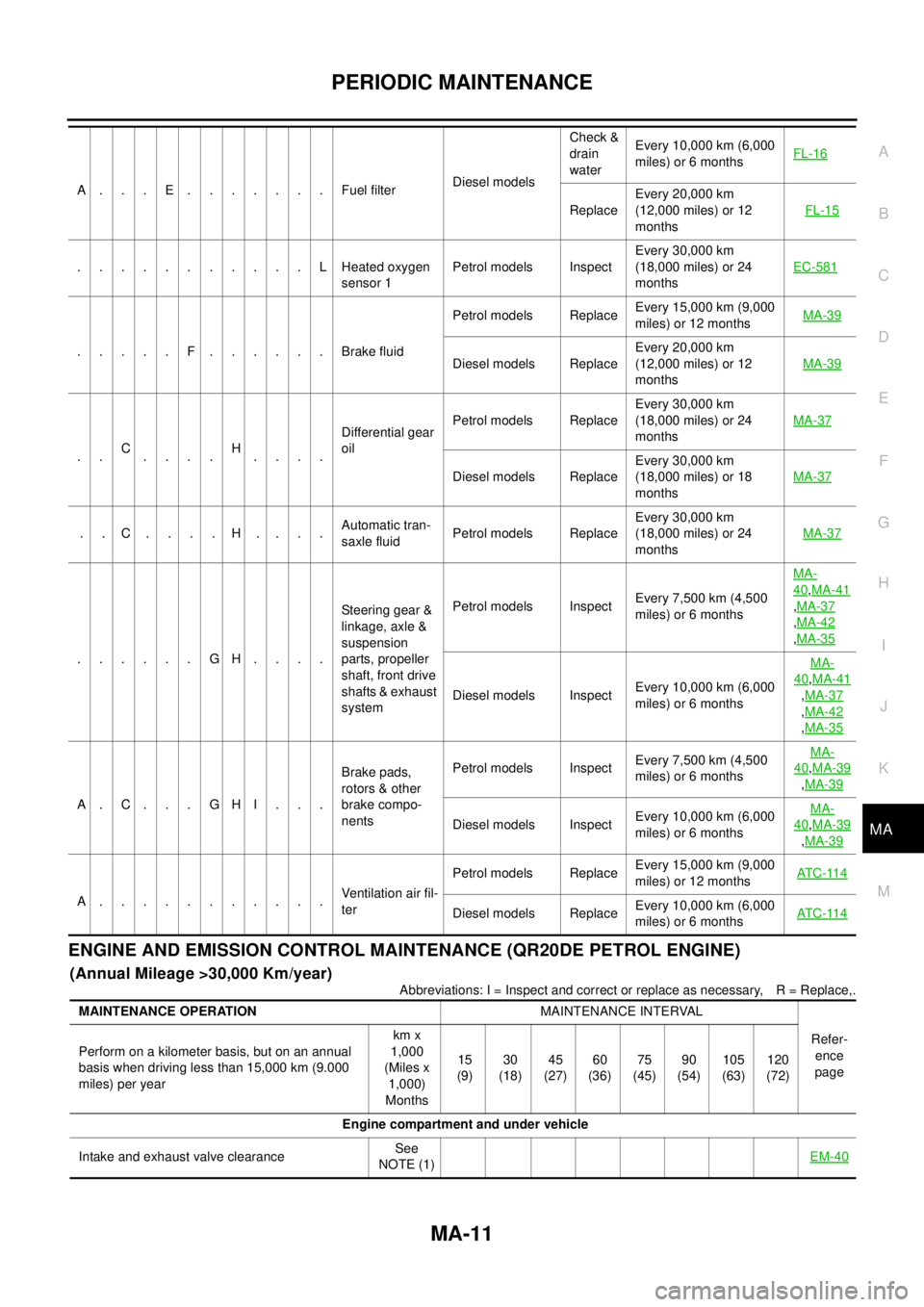
ENGINE AND EMISSION CONTROL MAINTENANCE (QR20DE PETROL ENGINE)
(Annual Mileage >30,000 Km/year)
Abbreviations: I = Inspect and correct or replace as necessary, R = Replace,. A...E.......FuelfilterDiesel modelsCheck &
drain
waterEvery 10,000 km (6,000
miles) or 6 monthsFL-16
ReplaceEvery 20,000 km
(12,000 miles) or 12
monthsFL-15
...........LHeatedoxygen
sensor 1Petrol models InspectEvery 30,000 km
(18,000 miles) or 24
monthsEC-581
.....F......BrakefluidPetrol models ReplaceEvery 15,000 km (9,000
miles) or 12 monthsMA-39Diesel models ReplaceEvery 20,000 km
(12,000 miles) or 12
monthsMA-39
..C
....H
....Differential gear
oilPetrol models ReplaceEvery 30,000 km
(18,000 miles) or 24
monthsMA-37
Diesel models ReplaceEvery 30,000 km
(18,000 miles) or 18
monthsMA-37
..C....H....Automatic tran-
saxle fluidPetrol models ReplaceEvery 30,000 km
(18,000 miles) or 24
monthsMA-37
......GH....Steering gear &
linkage, axle &
suspension
parts, propeller
shaft, front drive
shafts & exhaust
systemPetrol models InspectEvery 7,500 km (4,500
miles) or 6 monthsMA-
40,MA-41
,MA-37
,MA-42
,MA-35
Diesel models InspectEvery 10,000 km (6,000
miles) or 6 monthsMA-
40,MA-41
,MA-37
,MA-42
,MA-35
A.C...GHI...Brake pads,
rotors & other
brake compo-
nentsPetrol models InspectEvery 7,500 km (4,500
miles) or 6 monthsMA-
40,MA-39
,MA-39
Diesel models InspectEvery 10,000 km (6,000
miles) or 6 monthsMA-40,MA-39
,MA-39
A...........Ventilation air fil-
terPetrol models ReplaceEvery 15,000 km (9,000
miles) or 12 monthsAT C -11 4Diesel models ReplaceEvery 10,000 km (6,000
miles) or 6 monthsAT C -11 4
MAINTENANCE OPERATIONMAINTENANCE INTERVAL
Refer-
ence
page Perform on a kilometer basis, but on an annual
basis when driving less than 15,000 km (9.000
miles) per yearkm x
1,000
(Miles x
1,000)
Months15
(9)30
(18)45
(27)60
(36)75
(45)90
(54)105
(63)120
(72)
Engine compartment and under vehicle
Intake and exhaust valve clearanceSee
NOTE (1)EM-40
Page 2504 of 3066
MA-12
PERIODIC MAINTENANCE
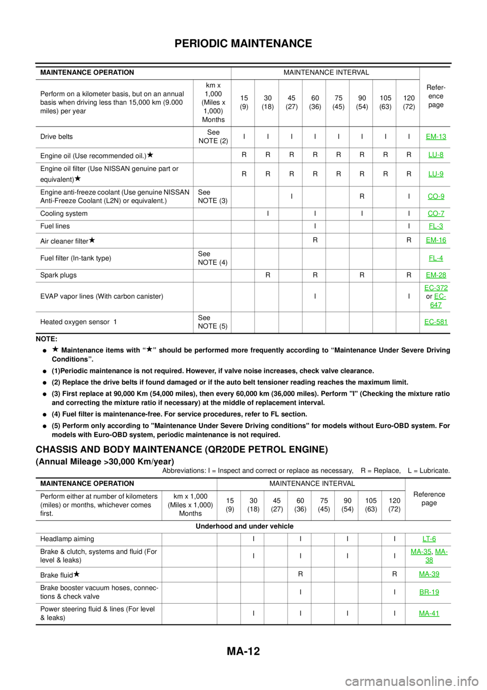
NOTE:
lMaintenance items with “ ” should be performed more frequently according to “Maintenance Under Severe Driving
Conditions”.
l(1)Periodic maintenance is not required. However, if valve noise increases, check valve clearance.
l(2) Replace the drive belts if found damaged or if the auto belt tensioner reading reaches the maximum limit.
l(3) First replace at 90,000 Km (54,000 miles), then every 60,000 km (36,000 miles). Perform "I" (Checking the mixture ratio
and correcting the mixture ratio if necessary) at the middle of replacement interval.
l(4) Fuel filter is maintenance-free. For service procedures, refer to FL section.
l(5) Perform only according to "Maintenance Under Severe Driving conditions" for models without Euro-OBD system. For
models with Euro-OBD system, periodic maintenance is not required.
CHASSIS AND BODY MAINTENANCE (QR20DE PETROL ENGINE)
(Annual Mileage >30,000 Km/year)
Abbreviations: I = Inspect and correct or replace as necessary, R = Replace, L = Lubricate. Drive beltsSee
NOTE (2)IIIIIIIIEM-13
Engine oil (Use recommended oil.)R R RRRRRRLU-8
Engine oil filter (Use NISSAN genuine part or
equivalent)R R RRRRRRLU-9
Engine anti-freeze coolant (Use genuine NISSAN
Anti-Freeze Coolant (L2N) or equivalent.)See
NOTE (3)IRICO-9
Cooling system I I I ICO-7
Fuel linesIIFL-3
Air cleaner filterRREM-16
Fuel filter (In-tank type)See
NOTE (4)FL-4
Spark plugs R R R REM-28
EVAP vapor lines (With carbon canister) I IEC-372orEC-
647
Heated oxygen sensor 1See
NOTE (5)EC-581
MAINTENANCE OPERATIONMAINTENANCE INTERVAL
Refer-
ence
page Perform on a kilometer basis, but on an annual
basis when driving less than 15,000 km (9.000
miles) per yearkm x
1,000
(Miles x
1,000)
Months15
(9)30
(18)45
(27)60
(36)75
(45)90
(54)105
(63)120
(72)
MAINTENANCE OPERATIONMAINTENANCE INTERVAL
Reference
page Perform either at number of kilometers
(miles) or months, whichever comes
first.km x 1,000
(Miles x 1,000)
Months15
(9)30
(18)45
(27)60
(36)75
(45)90
(54)105
(63)120
(72)
Underhood and under vehicle
Headlamp aiming I I I ILT- 6
Brake & clutch, systems and fluid (For
level & leaks)IIIIMA-35,MA-
38
Brake fluidRRMA-39
Brake booster vacuum hoses, connec-
tions & check valveIIBR-19
Power steering fluid & lines (For level
&leaks)IIIIMA-41
Page 2507 of 3066
PERIODIC MAINTENANCE
MA-15
C
D
E
F
G
H
I
J
K
MA
B
MA
NOTE:
l(1) Inspect once per year.
lMaintenance items with “ ” should be performed more frequently according to “Maintenance Under Severe Driving
Conditions”.
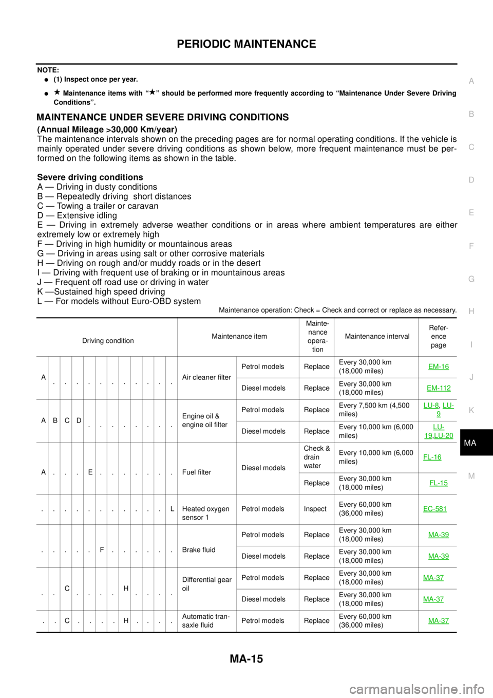
MAINTENANCE UNDER SEVERE DRIVING CONDITIONS
(Annual Mileage >30,000 Km/year)
The maintenance intervals shown on the preceding pages are for normal operating conditions. If the vehicle is
mainly operated under severe driving conditions as shown below, more frequent maintenance must be per-
formed on the following items as shown in the table.
Severe driving conditions
A — Driving in dusty conditions
B — Repeatedly driving short distances
C — Towing a trailer or caravan
D — Extensive idling
E — Driving in extremely adverse weather conditions or in areas where ambient temperatures are either
extremely low or extremely high
F — Driving in high humidity or mountainous areas
G — Driving in areas using salt or other corrosive materials
H — Driving on rough and/or muddy roads or in the desert
I — Driving with frequent use of braking or in mountainous areas
J — Frequent off road use or driving in water
K —Sustained high speed driving
L — For models without Euro-OBD system
Maintenance operation: Check = Check and correct or replace as necessary.
Driving conditionMaintenance itemMainte-
nance
opera-
tionMaintenance intervalRefer-
ence
page
A
...........Air cleaner filterPetrol models ReplaceEvery 30,000 km
(18,000 miles)EM-16
Diesel models ReplaceEvery 30,000 km
(18,000 miles)EM-112
ABCD
........Engine oil &
engine oil filterPetrol models ReplaceEvery 7,500 km (4,500
miles)LU-8
,LU-
9
Diesel models ReplaceEvery 10,000 km (6,000
miles)LU-19,LU-20
A...E.......FuelfilterDiesel modelsCheck &
drain
waterEvery 10,000 km (6,000
miles)FL-16
ReplaceEvery 30,000 km
(18,000 miles)FL-15
...........LHeatedoxygen
sensor 1Petrol models InspectEvery 60,000 km
(36,000 miles)EC-581
.....F......BrakefluidPetrol models ReplaceEvery 30,000 km
(18,000 miles)MA-39Diesel models ReplaceEvery 30,000 km
(18,000 miles)MA-39
..C
....H
....Differential gear
oilPetrol models ReplaceEvery 30,000 km
(18,000 miles)MA-37Diesel models ReplaceEvery 30,000 km
(18,000 miles)MA-37
..C....H....Automatic tran-
saxle fluidPetrol models ReplaceEvery 60,000 km
(36,000 miles)MA-37
Page 2737 of 3066
HARNESS
PG-61
C
D
E
F
G
H
I
J
L
MA
B
PG
Wiring Diagram Codes (Cell Codes)EKS0032J
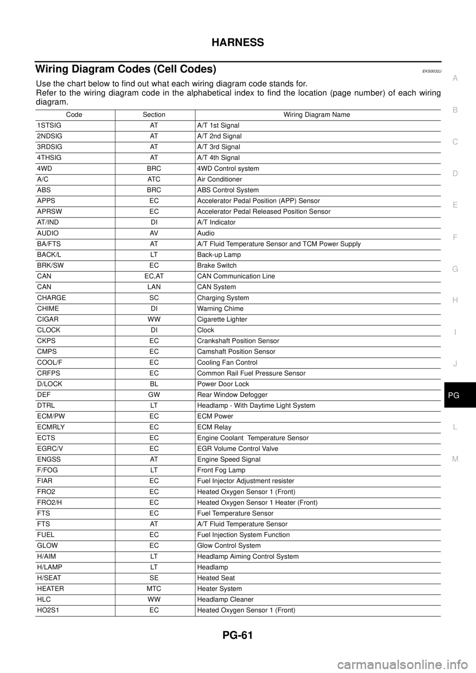
Use the chart below to find out what each wiring diagram code stands for.
Refer to the wiring diagram code in the alphabetical index to find the location (page number) of each wiring
diagram.
Code Section Wiring Diagram Name
1STSIG AT A/T 1st Signal
2NDSIG AT A/T 2nd Signal
3RDSIG AT A/T 3rd Signal
4THSIG AT A/T 4th Signal
4WD BRC 4WD Control system
A/C ATC Air Conditioner
ABS BRC ABS Control System
APPS EC Accelerator Pedal Position (APP) Sensor
APRSW EC Accelerator Pedal Released Position Sensor
AT/IND DI A/T Indicator
AUDIO AV Audio
BA/FTS AT A/T Fluid Temperature Sensor and TCM Power Supply
BACK/L LT Back-up Lamp
BRK/SW EC Brake Switch
CAN EC,AT CAN Communication Line
CAN LAN CAN System
CHARGE SC Charging System
CHIME DI Warning Chime
CIGAR WW Cigarette Lighter
CLOCK DI Clock
CKPS EC Crankshaft Position Sensor
CMPS EC Camshaft Position Sensor
COOL/F EC Cooling Fan Control
CRFPS EC Common Rail Fuel Pressure Sensor
D/LOCK BL Power Door Lock
DEF GW Rear Window Defogger
DTRL LT Headlamp - With Daytime Light System
ECM/PW EC ECM Power
ECMRLY EC ECM Relay
ECTS EC Engine Coolant Temperature Sensor
EGRC/V EC EGR Volume Control Valve
ENGSS AT Engine Speed Signal
F/FOG LT Front Fog Lamp
FIAR EC Fuel Injector Adjustment resister
FRO2 EC Heated Oxygen Sensor 1 (Front)
FRO2/H EC Heated Oxygen Sensor 1 Heater (Front)
FTS EC Fuel Temperature Sensor
FTS AT A/T Fluid Temperature Sensor
FUEL EC Fuel Injection System Function
GLOW EC Glow Control System
H/AIM LT Headlamp Aiming Control System
H/LAMP LT Headlamp
H/SEAT SE Heated Seat
HEATER MTC Heater System
HLC WW Headlamp Cleaner
HO2S1 EC Heated Oxygen Sensor 1 (Front)
Page 2803 of 3066
WHEEL HUB (4WD)
RAX-7
C
E
F
G
H
I
J
K
L
MA
B
RAX
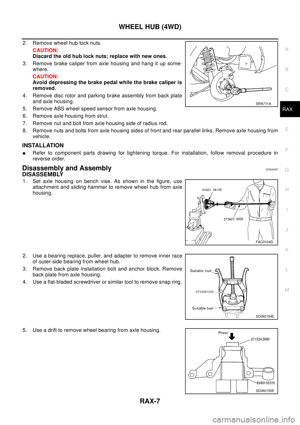
2. Remove wheel hub lock nuts.
CAUTION:
Discard the old hub lock nuts; replace with new ones.
3. Remove brake caliper from axle housing and hang it up some-
where.
CAUTION:
Avoid depressing the brake pedal while the brake caliper is
removed.
4. Remove disc rotor and parking brake assembly from back plate
andaxlehousing.
5. Remove ABS wheel speed sensor from axle housing.
6. Remove axle housing from strut.
7. Remove nut and bolt from axle housing side of radius rod.
8. Remove nuts and bolts from axle housing sides of front and rear parallel links. Remove axle housing from
vehicle.
INSTALLATION
lRefer to component parts drawing for tightening torque. For installation, follow removal procedure in
reverse order.
Disassembly and AssemblyEDS00067
DISASSEMBLY
1. Set axle housing on bench vise. As shown in the figure, use
attachment and sliding hammer to remove wheel hub from axle
housing.
2. Use a bearing replace, puller, and adapter to remove inner race
of outer-side bearing from wheel hub.
3. Remove back plate installation bolt and anchor block. Remove
back plate from axle housing.
4. Use a flat-bladed screwdriver or similar tool to remove snap ring.
5. Use a drift to remove wheel bearing from axle housing.
SRA711A
FAC0104D
SDIA0154E
SDIA0155E
Page 2833 of 3066
REAR FINAL DRIVE ASSEMBLY
RFD-11
C
E
F
G
H
I
J
K
L
MA
B
RFD
REAR FINAL DRIVE ASSEMBLYPFP:38300
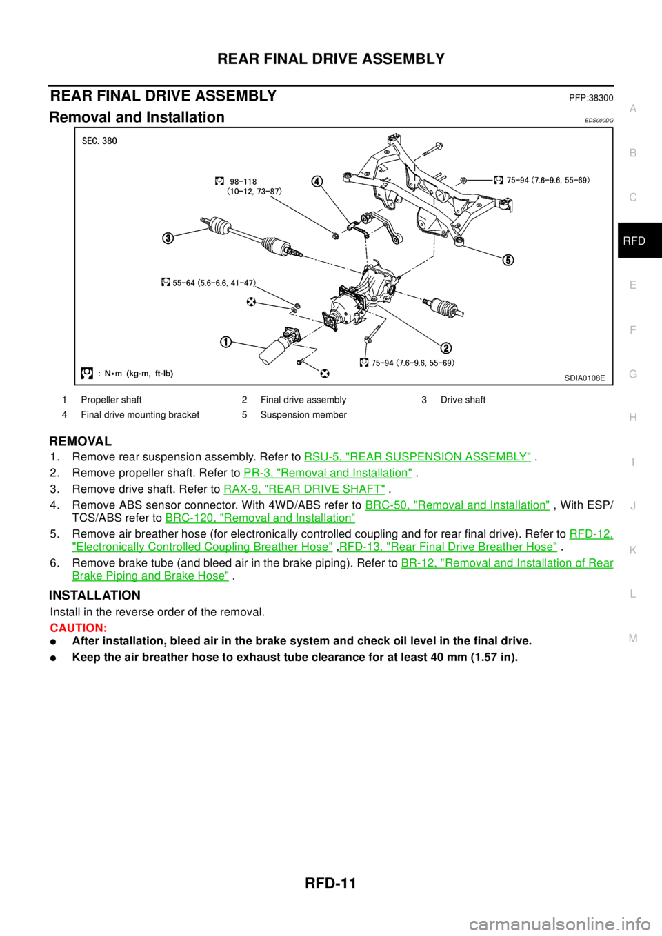
Removal and InstallationEDS000DG
REMOVAL
1. Remove rear suspension assembly. Refer toRSU-5, "REAR SUSPENSION ASSEMBLY".
2. Remove propeller shaft. Refer toPR-3, "
Removal and Installation".
3. Remove drive shaft. Refer toRAX-9, "
REAR DRIVE SHAFT".
4. Remove ABS sensor connector. With 4WD/ABS refer toBRC-50, "
Removal and Installation", With ESP/
TCS/ABS refer toBRC-120, "
Removal and Installation"
5. Remove air breather hose (for electronically controlled coupling and for rear final drive). Refer toRFD-12,
"Electronically Controlled Coupling Breather Hose",RFD-13, "Rear Final Drive Breather Hose".
6. Remove brake tube (and bleed air in the brake piping). Refer toBR-12, "
Removal and Installation of Rear
Brake Piping and Brake Hose".
INSTALLATION
Install in the reverse order of the removal.
CAUTION:
lAfter installation, bleed air in the brake system and check oil level in the final drive.
lKeep the air breather hose to exhaust tube clearance for at least 40 mm (1.57 in).
SDIA0108E
1 Propeller shaft 2 Final drive assembly 3 Drive shaft
4 Final drive mounting bracket 5 Suspension member
Page 2865 of 3066
REAR SUSPENSION MEMBER
RSU-13
C
D
F
G
H
I
J
K
L
MA
B
RSU
REAR SUSPENSION MEMBERPFP:55501
Removal and InstallationEES0007M
REMOVAL
1. Remove tires. Raise vehicle.
2. Remove cotter pin.Remove wheel hub lock nut by using a wheel hub lock nut wrench.
3. Remove ABS wheel speed sensor and wiring (With ABS models).
4. Remove brake caliper and brake hose lock plate, and hang them aside.
5. Remove mounting bolts and nuts on lower portion of strut.
6. Remove axle-side mounting bolts of parallel link and remove rear drive shaft from axle housing.
7. Remove suspension member-side mounting bolt of parallel link and remove parallel link from suspension
member.
8. Remove mounting bolts and nuts on lower portion of strut.
CAUTION:
After removing drive shaft, position axle housing onto strut.
9. Remove propeller shaft.
10. Remove rear exhaust tube.
11. Remove electronically controlled coupling connector and air breather hose from final drive.
12. Set a transmission jack under rear final drive.
13. Remove front and rear mounting bolts from rear final drive.
14. Remove rear final drive from suspension member.
15. Place transmission jack onto rear suspension member. Remove rear suspension member mounting bolts.
Lower transmission jack slowly to remove rear suspension member from vehicle.
INSTALLATION
lRefer toRSU-5, "Components"for tightening torque. Install in the reverse order of removal.
lAfter installation, perform final tightening of each part under unladen conditions with tires on ground.
Check wheel alignment.RSU-6, "
Wheel Alignment".