Page 3018 of 3502
MA-40
CHASSIS AND BODY MAINTENANCE
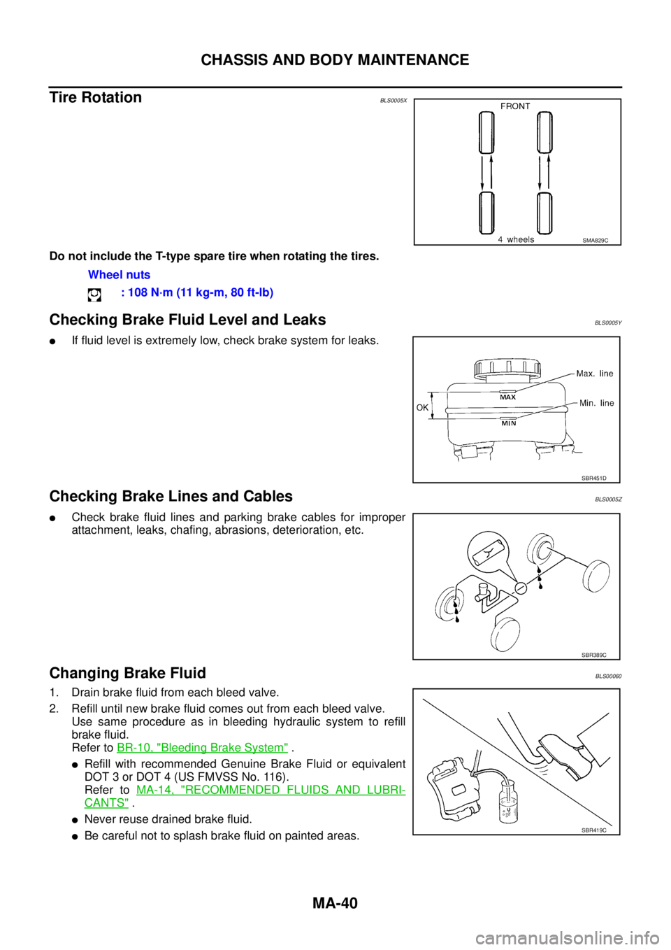
Tire RotationBLS0005X
Do not include the T-type spare tire when rotating the tires.
Checking Brake Fluid Level and LeaksBLS0005Y
�If fluid level is extremely low, check brake system for leaks.
Checking Brake Lines and CablesBLS0005Z
�Check brake fluid lines and parking brake cables for improper
attachment, leaks, chafing, abrasions, deterioration, etc.
Changing Brake FluidBLS00060
1. Drain brake fluid from each bleed valve.
2. Refill until new brake fluid comes out from each bleed valve.
Use same procedure as in bleeding hydraulic system to refill
brake fluid.
Refer to BR-10, "
Bleeding Brake System" .
�Refill with recommended Genuine Brake Fluid or equivalent
DOT 3 or DOT 4 (US FMVSS No. 116).
Refer to MA-14, "
RECOMMENDED FLUIDS AND LUBRI-
CANTS" .
�Never reuse drained brake fluid.
�Be careful not to splash brake fluid on painted areas.
SMA829C
Wheel nuts
: 108 N·m (11 kg-m, 80 ft-lb)
SBR451D
SBR389C
SBR419C
Page 3157 of 3502

PS-43
C
D
E
F
H
I
J
K
L
MA
B
PS
Steering GearBGS00046
STEERING OUTER SOCKET AND INNER SOCKET
RACK STROKE
RACK SLIDING FORCE
Oil PumpBGS00048
Steering FluidBGS00")
SERVICE DATA AND SPECIFICATIONS (SDS)
PS-43
C
D
E
F
H
I
J
K
L
MA
B
PS
Steering GearBGS00046
STEERING OUTER SOCKET AND INNER SOCKET
RACK STROKE
RACK SLIDING FORCE
Oil PumpBGS00048
Steering FluidBGS00049
Steering gear typePR26AM
Outer socketSwinging torque 0.3 – 2.9 N·m (0.03 – 0.29 kg-m, 3 – 25 in-lb)
Measurement on spring balance
�Measuring point at cotter pin hole of stud4.84 – 46.7 N (0.5 – 4.8 kg, 1 – 10 lb)
Rotating torque 0.3 – 2.9 N·m (0.03 – 0.29 kg-m, 3 – 25 in-lb)
Axial end play 0.5 mm (0.020 in) or less
Inner socketSwinging torque 1.0 – 7.8 N·m (0.11 – 0.79 kg-m, 9 – 69 in-lb)
Measurement on spring balance
�Measuring point at *mark shown in the figure12.1 – 93.7 N (1.2 – 9.6 kg, 3 – 21 lb)
Axial end play 0.2 mm (0.008 in) or less
Inner socket length L127.3 mm (5.01 in)
SGIA0950E
Steering gear typePR26AM
Tire size 205/65R16 215/55R17
Rack stroke neutral position, dimension L (rack stroke) 73.5 mm (2.894 in) 68.5 mm (2.697 in)
SGIA0629J
Rack sliding force 210.6 – 269.4 N (21.5 – 27.5 kg, 47 – 61 lb)
Oil pump relief hydraulic pressureExcept for QR20DE models8,000 – 8,800 kPa
(80 – 88 bar, 81.6 – 89.8 kg/cm
2 , 1,160 – 1,276 psi)
QR20DE models9,000 – 9,800 kPa
(90 – 98 bar, 91.8 – 100 kg/cm
2 , 1,305 – 1,421 psi)
Fluid capacity
Approx. 1.0 (7/8 Imp qt)
Page 3377 of 3502
 “AIR BAG” and “SEAT
BELT PRE-TENSIONER”
BHS0003U
The Supplemental Restr")
PRECAUTIONS
SRS-3
C
D
E
F
G
I
J
K
L
MA
B
SRS
PRECAUTIONSPFP:00001
Precautions for Supplemental Restraint System (SRS) “AIR BAG” and “SEAT
BELT PRE-TENSIONER”
BHS0003U
The Supplemental Restraint System such as “AIR BAG” and “SEAT BELT PRE-TENSIONER”, used along
with a front seat belt, helps to reduce the risk or severity of injury to the driver and front passenger for certain
types of collision. Information necessary to service the system safely is included in the SRS and SB section of
this Service Manual.
WARNING:
�To avoid rendering the SRS inoperative, which could increase the risk of personal injury or death
in the event of a collision which would result in air bag inflation, all maintenance must be per-
formed by an authorized NISSAN/INFINITI dealer.
�Improper maintenance, including incorrect removal and installation of the SRS, can lead to per-
sonal injury caused by unintentional activation of the system. For removal of Spiral Cable and Air
Bag Module, see the SRS section.
�Do not use electrical test equipment on any circuit related to the SRS unless instructed to in this
Service Manual. SRS wiring harnesses can be identified by yellow and/or orange harnesses or
harness connectors.
Precautions for SRS “AIR BAG” and “SEAT BELT PRE-TENSIONER” ServiceBHS0003V
�Do not use electrical test equipment to check SRS circuits unless instructed to in this Service Manual.
�Before servicing the SRS, turn ignition switch OFF, and disconnect both battery cables. Then wait at least
3 minutes.
For approximately 3 minutes after the cables are removed, it is still possible for the air bag and seat belt
pre-tensioner to deploy. Therefore, do not work on any SRS connectors or wires until at least 3 minutes
have passed.
�Diagnosis sensor unit must always be installed with their arrow marks “⇐” pointing towards the front of the
vehicle for proper operation. Also check diagnosis sensor unit for cracks, deformations or rust before
installation and replace if required.
�The spiral cable must be set to the neutral position since its rotations are limited. Do not attempt to turn
steering wheel or column, if steering gear was disconnected from the column shaft.
�Handle air bag module carefully. Always put a driver air bag module with the pad side facing upward.
�Conduct self-diagnosis to check entire SRS for proper function after replacing any components.
�After an air bag is deployed, the front instrument panel assembly should be replaced if damaged.
�Always replace instrument panel pad following front passenger air bag deployment.