Page 2121 of 3502
![NISSAN TEANA 2003 Service Manual NOISE, VIBRATION AND HARSHNESS (NVH) TROUBLESHOOTING
EM-13
[QR]
C
D
E
F
G
H
I
J
K
L
MA
EM
Use the Chart Below to Help You Find the Cause of the Symptom.BBS0058R
1. Locate the area where noise occurs](/manual-img/5/57392/w960_57392-2120.png "NISSAN TEANA 2003 Service Manual NOISE, VIBRATION AND HARSHNESS (NVH) TROUBLESHOOTING
EM-13
[QR]
C
D
E
F
G
H
I
J
K
L
MA
EM
Use the Chart Below to Help You Find the Cause of the Symptom.BBS0058R
1. Locate the area where noise occurs")
NOISE, VIBRATION AND HARSHNESS (NVH) TROUBLESHOOTING
EM-13
[QR]
C
D
E
F
G
H
I
J
K
L
MA
EM
Use the Chart Below to Help You Find the Cause of the Symptom.BBS0058R
1. Locate the area where noise occurs.
2. Confirm the type of noise.
3. Specify the operating condition of engine.
4. Check specified noise source.
If necessary, repair or replace these parts.
A: Closely related B: Related C: Sometimes related —: Not relatedLocation
of noiseType of
noiseOperating condition of engine
Source of
noiseCheck itemRefer-
ence page Before
warm-
upAfter
warm-
upWhen
start-
ingWhen
idlingWhen
racingWhile
driving
Top of
engine
Rocker
cover
Cylinder
headTicking or
clickingCA—AB—Tappet
noiseValve clearanceEM-50
Rattle C A — A B CCamshaft
bearing
noiseCamshaft journal oil
clearance
Camshaft runoutEM-44EM-44
Crank-
shaft pul-
ley
Cylinder
block
(Side of
engine)
Oil panSlap or
knock—A—BB—Piston pin
noisePiston to piston pin oil
clearance
Connecting rod bush-
ing oil clearanceEM-99
EM-101
Slap or
rapA ——BBAPiston
slap noisePiston to cylinder bore
clearance
Piston ring side clear-
ance
Piston ring end gap
Connecting rod bend
and torsionEM-104EM-100
EM-100
EM-101
Knock A B C B B BConnect-
ing rod
bearing
noiseConnecting rod bush-
ing oil clearance
Connecting rod bear-
ing oil clearanceEM-101EM-105
Knock A B — A B CMain
bearing
noiseMain bearing oil clear-
ance
Crankshaft runoutEM-106EM-105
Front of
engine
Front
coverTapping or
tickingA A —BBBTiming
chain and
chain ten-
sioner
noiseTiming chain cracks
and wear
Timing chain tensioner
operationEM-57
EM-53
Front of
engineSqueak-
ing or fizz-
ingAB—B—CDrive belt
(Sticking
or slip-
ping)Drive belt deflection
EM-14
CreakingA B ABABDrive belt
(Slipping)Idler pulley bearing
operation
Squall
CreakA B —BABWater
pump
noiseWater pump operationCO-22,
"WATER
PUMP"
Page 2123 of 3502
![NISSAN TEANA 2003 Service Manual DRIVE BELTS
EM-15
[QR]
C
D
E
F
G
H
I
J
K
L
MA
EM
INSTALLATION
1. With box wrench, and while securely holding the hexagonal part
in center of drive belt auto-tensioner pulley, move the wrench
handle](/manual-img/5/57392/w960_57392-2122.png "NISSAN TEANA 2003 Service Manual DRIVE BELTS
EM-15
[QR]
C
D
E
F
G
H
I
J
K
L
MA
EM
INSTALLATION
1. With box wrench, and while securely holding the hexagonal part
in center of drive belt auto-tensioner pulley, move the wrench
handle")
DRIVE BELTS
EM-15
[QR]
C
D
E
F
G
H
I
J
K
L
MA
EM
INSTALLATION
1. With box wrench, and while securely holding the hexagonal part
in center of drive belt auto-tensioner pulley, move the wrench
handle in the direction of arrow (loosening direction of ten-
sioner).
CAUTION:
�Avoid placing hand in a location where pinching may
occur if the holding tool accidentally comes off.
�Do not loosen the hexagonal part in center of drive belt
auto-tensioner pulley (Do not turn it counterclockwise). If
turned counterclockwise, the complete drive belt auto-
tensioner must be replaced as a unit, including the pul-
ley.
2. Insert a rod approximately 6 mm (0.24 in) in diameter such as short-length screwdriver into the hole of
retaining boss to fix drive belt auto-tensioner pulley.
3. Hook drive belt onto all pulleys except for water pump, and then onto water pump pulley finally.
CAUTION:
�Confirm belt is completely set to pulleys.
�Check for engine oil, working fluid and engine coolant are not adhered to drive belt and each
pulley groove.
4. Release drive belt auto-tensioner, and apply tension to drive belt.
5. Turn crankshaft pulley clockwise several times to equalize tension between each pulley.
6. Confirm tension of drive belt at indicator (notch on fixed side) is within the possible use range. Refer to
EM-14, "
Checking Drive Belts" .
Removal and Installation of Drive Belt Auto-TensionerBBS0058V
CAUTION:
The complete drive belt auto-tensioner must be replaced as a unit, including the pulley.
REMOVAL
1. Remove splash guard (RH).
2. Remove drive belt. Refer to EM-14, "
Removal and Installation" .
3. Release the fixed drive belt auto-tensioner pulley.
4. Remove drive belt auto-tensioner.
PBIC2627E
1. Drive belt auto-tensioner 2. Water pump pulley
PBIC2170E
Page 2134 of 3502
![NISSAN TEANA 2003 Service Manual EM-26
[QR]
OIL PAN AND OIL STRAINER
OIL PAN AND OIL STRAINERP F P : 1111 0
Removal and InstallationBBS00590
REMOVAL
WARNING:
To avoid the danger of being scalded, do not drain the engine oil when th](/manual-img/5/57392/w960_57392-2133.png "NISSAN TEANA 2003 Service Manual EM-26
[QR]
OIL PAN AND OIL STRAINER
OIL PAN AND OIL STRAINERP F P : 1111 0
Removal and InstallationBBS00590
REMOVAL
WARNING:
To avoid the danger of being scalded, do not drain the engine oil when th")
EM-26
[QR]
OIL PAN AND OIL STRAINER
OIL PAN AND OIL STRAINERP F P : 1111 0
Removal and InstallationBBS00590
REMOVAL
WARNING:
To avoid the danger of being scalded, do not drain the engine oil when the engine is hot.
NOTE:
When removing oil pan (lower) or oil strainer only, take step 2 then step 8 and 9, the other steps are unneces-
sary.
1. Remove undercover and splash guard (RH).
2. Drain engine oil. Refer to LU-9, "
Changing Engine Oil" .
CAUTION:
�Perform this step when engine is cold.
�Do not spill engine oil on drive belt.
3. Remove drive belt. Refer to EM-14, "
DRIVE BELTS" .
4. Remove exhaust front tube. Refer to EX-2, "
EXHAUST SYSTEM" .
5. Remove A/C compressor with piping connected. And locate it aside temporarily with ropes or equivalent
not to disturb the following work. Refer to ATC-134, "
Removal and Installation of Compressor" .
6. Remove oil level gauge guide.
7. Remove oil filter. Refer to LU-10, "
OIL FILTER" .
8. Remove oil pan (lower) with the following procedure:
1. Oil level gauge 2. Oil level gauge guide 3. O-ring
4. Oil pan (upper) 5. Cylinder block 6. O-ring
7. Oil filter 8. O-ring 9. Drain plug washer
10. Oil strainer 11. Drain plug 12. Oil pan (lower)
13. Rear plate cover
PBIC2177E
Page 2135 of 3502
![NISSAN TEANA 2003 Service Manual OIL PAN AND OIL STRAINER
EM-27
[QR]
C
D
E
F
G
H
I
J
K
L
MA
EM
a. Loosen mounting bolts in reverse order as shown in the figure.
b. Insert seal cutter (SST) between oil pan (upper) and oil pan
(lower](/manual-img/5/57392/w960_57392-2134.png "NISSAN TEANA 2003 Service Manual OIL PAN AND OIL STRAINER
EM-27
[QR]
C
D
E
F
G
H
I
J
K
L
MA
EM
a. Loosen mounting bolts in reverse order as shown in the figure.
b. Insert seal cutter (SST) between oil pan (upper) and oil pan
(lower")
OIL PAN AND OIL STRAINER
EM-27
[QR]
C
D
E
F
G
H
I
J
K
L
MA
EM
a. Loosen mounting bolts in reverse order as shown in the figure.
b. Insert seal cutter (SST) between oil pan (upper) and oil pan
(lower).
CAUTION:
�Be careful not to damage the mating surfaces.
�Do not insert screwdriver, this will damage the mating
surfaces.
c. Slide seal cutter by tapping on the side of the tool with hammer.
9. Remove oil strainer.
10. Remove oil pan (upper) with the following procedure:
a. Remove rear plate cover, and four transaxle joint bolts. Refer to AT- 2 4 1 , "
TRANSAXLE ASSEMBLY" .
b. Securely support bottom of transaxle with suitable transmission jack.
c. Remove engine mounting related parts below. Refer to EM-77, "
ENGINE ASSEMBLY" .
�RH engine mounting insulator bolts (vehicle side)
�Front engine mounting through-bolt
�Rear engine mounting through-bolt
d. Loosen bolts in reverse order as shown in the figure.
NOTE:
Disregard No.12 and 17 when loosening.
e. Insert seal cutter (SST) between oil pan (upper) and cylinder
block, and slide it by tapping on the side of the tool with hammer.
CAUTION:
�Be careful not to damage the mating surfaces.
�Do not insert screwdriver, this will damage the mating
surfaces.
f. Lift up engine and transaxle assembly with transmission jack to make a room for pulling oil pan (upper)
out.
KBIA0096E
SEM365EA
SBIA0233E
SEM365EA
Page 2136 of 3502
![NISSAN TEANA 2003 Service Manual EM-28
[QR]
OIL PAN AND OIL STRAINER
g. Pull oil pan (upper) out.
11. Remove O-rings at front cover side.
INSPECTION AFTER REMOVAL
Oil Strainer
Clean oil strainer if any object attached.
INSTALLATION](/manual-img/5/57392/w960_57392-2135.png "NISSAN TEANA 2003 Service Manual EM-28
[QR]
OIL PAN AND OIL STRAINER
g. Pull oil pan (upper) out.
11. Remove O-rings at front cover side.
INSPECTION AFTER REMOVAL
Oil Strainer
Clean oil strainer if any object attached.
INSTALLATION")
EM-28
[QR]
OIL PAN AND OIL STRAINER
g. Pull oil pan (upper) out.
11. Remove O-rings at front cover side.
INSPECTION AFTER REMOVAL
Oil Strainer
Clean oil strainer if any object attached.
INSTALLATION
1. Install oil pan (upper) with the following procedure:
a. Use scraper to remove old liquid gasket from mating surfaces.
�Also remove the old liquid gasket from mating surface of cyl-
inder block.
�Remove old liquid gasket from the bolt holes and threads.
CAUTION:
Do not scratch or damage the mating surfaces when clean-
ing off old liquid gasket.
b. Apply a continuous bead of liquid gasket with tube presser [SST:
WS39930000] as shown in the figure.
Use Genuine Liquid Gasket or equivalent.
CAUTION:
�Apply liquid gasket to outside of bolt hole for the posi-
tions shown by arrows.
�Attaching should be done within 5 minutes after coating.
c. Install new O-rings at front cover side.
d. Tighten bolts in numerical order as shown in the figure.
NOTE:
�No. 12 and 17 mean double tightening of bolts No. 1 and 2.
�Refer to the following for locating bolts.
e. Tighten transaxle joint bolts. Refer to AT- 2 4 1 , "
TRANSAXLE ASSEMBLY" .
f. Install rear plate cover.
g. Install engine mounting related parts below. Refer to EM-77, "
ENGINE ASSEMBLY" .
�RH engine mounting insulator bolts (vehicle side)
�Front engine mounting through-bolt
�Rear engine mounting through-bolt
h. Release supporting with the transmission jack.
2. Install oil strainer.
3. Install oil pan (lower) with the following procedure:
MEM108A
SBIA0253E
M6 × 20 mm (0.79 in) : No. 18, 19
M8 × 25 mm (0.98 in) : No. 1, 2, 3, 11
M8 × 45 mm (1.77 in) : No. 4, 10, 13, 14, 15, 16
M8 × 100 mm (3.97 in) : No. 5, 6, 7, 8, 9
SBIA0233E
Page 2137 of 3502
OIL PAN AND OIL STRAINER
EM-29
[QR]
C
D
E
F
G
H
I
J
K
L
MA
EM
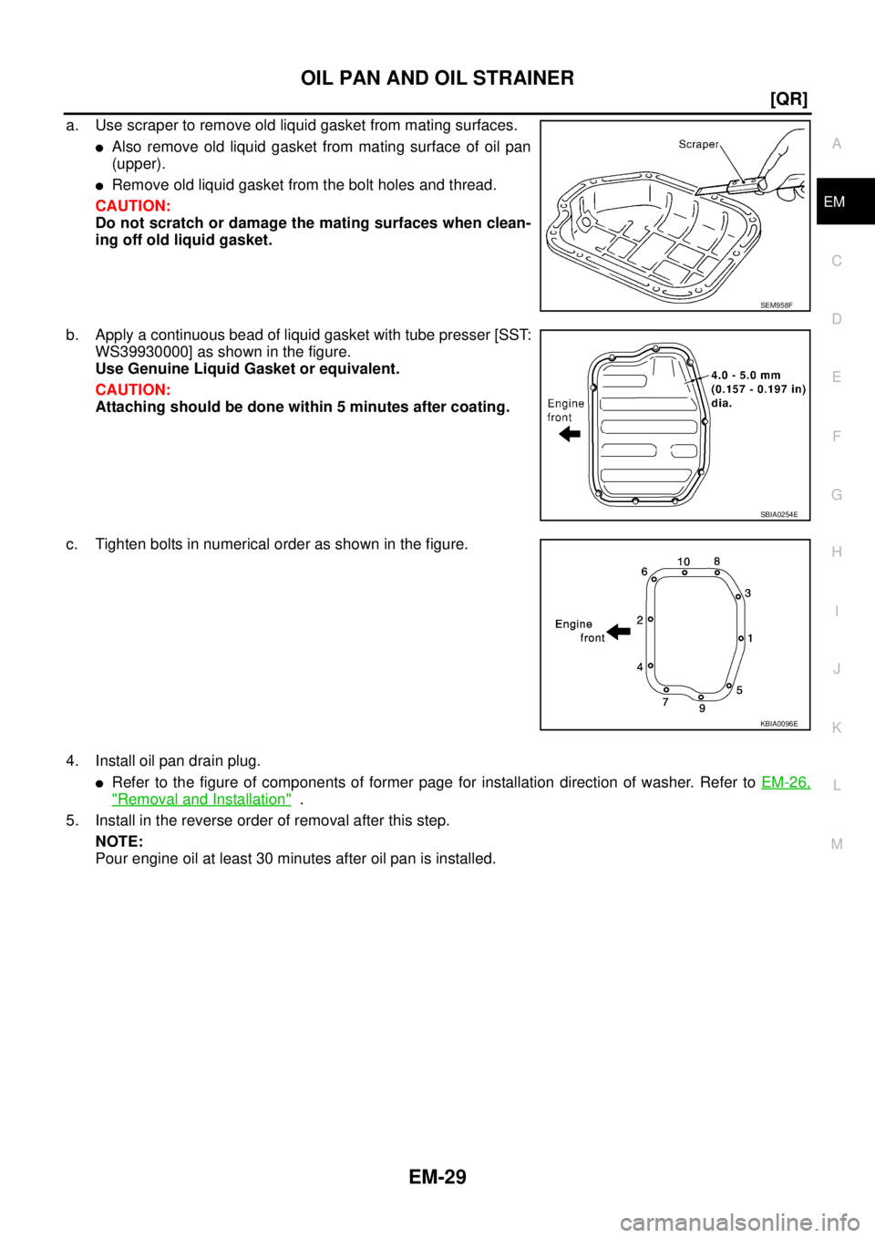
a. Use scraper to remove old liquid gasket from mating surfaces.
�Also remove old liquid gasket from mating surface of oil pan
(upper).
�Remove old liquid gasket from the bolt holes and thread.
CAUTION:
Do not scratch or damage the mating surfaces when clean-
ing off old liquid gasket.
b. Apply a continuous bead of liquid gasket with tube presser [SST:
WS39930000] as shown in the figure.
Use Genuine Liquid Gasket or equivalent.
CAUTION:
Attaching should be done within 5 minutes after coating.
c. Tighten bolts in numerical order as shown in the figure.
4. Install oil pan drain plug.
�Refer to the figure of components of former page for installation direction of washer. Refer to EM-26,
"Removal and Installation" .
5. Install in the reverse order of removal after this step.
NOTE:
Pour engine oil at least 30 minutes after oil pan is installed.
SEM958F
SBIA0254E
KBIA0096E
Page 2138 of 3502
EM-30
[QR]
OIL PAN AND OIL STRAINER
INSPECTION AFTER INSTALLATION
1. Check engine oil level and adjust engine oil. Refer to LU-7, "ENGINE OIL" .
2. Start engine, and make sure there is no leaks of engine oil.
3. Stop engine and wait for 10 minutes.
4. Check engine oil level again. Refer to LU-7, "
ENGINE OIL" .
Page 2139 of 3502
IGNITION COIL
EM-31
[QR]
C
D
E
F
G
H
I
J
K
L
MA
EM
IGNITION COILPFP:22448
Removal and InstallationBBS00591
REMOVAL
1. Remove engine cover. Refer to EM-19, "INTAKE MANIFOLD" .
2. Disconnect harness connector from ignition coil.
3. Remove ignition coil.
CAUTION:
Do not drop or shock it.
INSTALLATION
Installation is the reverse order of removal.
1. Ignition coil 2. Spark plug 3. Rocker cover
KBIA1974J
![NISSAN TEANA 2003 Service Manual EM-30
[QR]
OIL PAN AND OIL STRAINER
INSPECTION AFTER INSTALLATION
1. Check engine oil level and adjust engine oil. Refer to LU-7, "ENGINE OIL" .
2. Start engine, and make sure there is no leaks of](/manual-img/5/57392/w960_57392-2137.png "NISSAN TEANA 2003 Service Manual EM-30
[QR]
OIL PAN AND OIL STRAINER
INSPECTION AFTER INSTALLATION
1. Check engine oil level and adjust engine oil. Refer to LU-7, \"ENGINE OIL\" .
2. Start engine, and make sure there is no leaks of")
![NISSAN TEANA 2003 Service Manual IGNITION COIL
EM-31
[QR]
C
D
E
F
G
H
I
J
K
L
MA
EM
IGNITION COILPFP:22448
Removal and InstallationBBS00591
REMOVAL
1. Remove engine cover. Refer to EM-19, "INTAKE MANIFOLD" .
2. Disconnect harness](/manual-img/5/57392/w960_57392-2138.png "NISSAN TEANA 2003 Service Manual IGNITION COIL
EM-31
[QR]
C
D
E
F
G
H
I
J
K
L
MA
EM
IGNITION COILPFP:22448
Removal and InstallationBBS00591
REMOVAL
1. Remove engine cover. Refer to EM-19, \"INTAKE MANIFOLD\" .
2. Disconnect harness")