Page 2453 of 3189
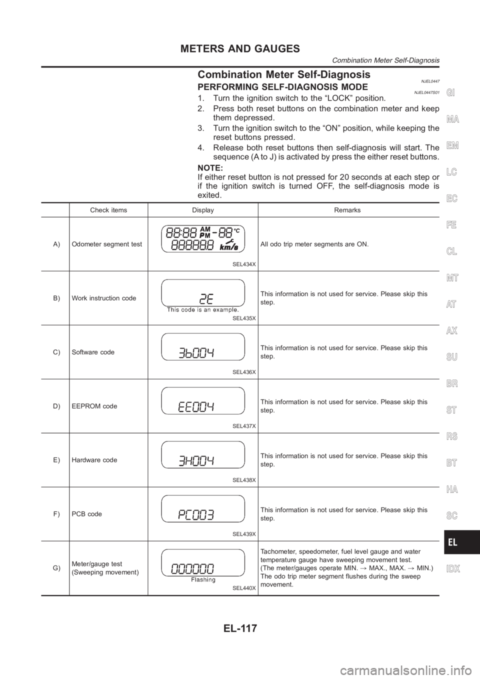
Combination Meter Self-DiagnosisNJEL0447PERFORMING SELF-DIAGNOSIS MODENJEL0447S011. Turn the ignition switch to the “LOCK” position.
2. Press both reset buttons on the combination meter and keep
them depressed.
3. Turn the ignition switch to the “ON” position, while keeping the
reset buttons pressed.
4. Release both reset buttons then self-diagnosis will start. The
sequence (A to J) is activated by press the either reset buttons.
NOTE:
If either reset button is not pressed for 20 seconds at each step or
if the ignition switch is turned OFF, the self-diagnosis mode is
exited.
Check items Display Remarks
A) Odometer segment test
SEL434X
All odo trip meter segments are ON.
B) Work instruction code
SEL435X
This information is not used for service. Please skip this
step.
C) Software code
SEL436X
This information is not used for service. Please skip this
step.
D) EEPROM code
SEL437X
This information is not used for service. Please skip this
step.
E) Hardware code
SEL438X
This information is not used for service. Please skip this
step.
F) PCB code
SEL439X
This information is not used for service. Please skip this
step.
G)Meter/gauge test
(Sweeping movement)
SEL440X
Tachometer, speedometer, fuel level gauge and water
temperature gauge have sweeping movement test.
(The meter/gauges operate MIN.,MAX., MAX.,MIN.)
The odo trip meter segment flushes during the sweep
movement.
GI
MA
EM
LC
EC
FE
CL
MT
AT
AX
SU
BR
ST
RS
BT
HA
SC
IDX
METERS AND GAUGES
Combination Meter Self-Diagnosis
EL-117
Page 2456 of 3189
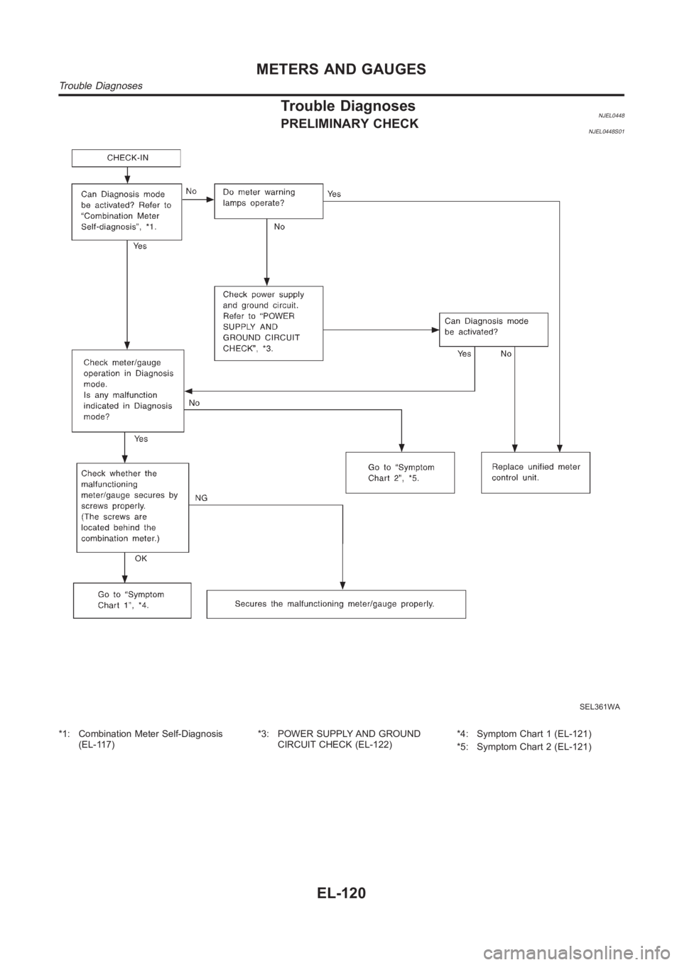
Trouble DiagnosesNJEL0448PRELIMINARY CHECKNJEL0448S01
SEL361WA
*1: Combination Meter Self-Diagnosis
(EL-117)*3: POWER SUPPLY AND GROUND
CIRCUIT CHECK (EL-122)*4: Symptom Chart 1 (EL-121)
*5: Symptom Chart 2 (EL-121)
METERS AND GAUGES
Trouble Diagnoses
EL-120
Page 2572 of 3189
3 VEHICLE SPEED SIGNAL CHECK
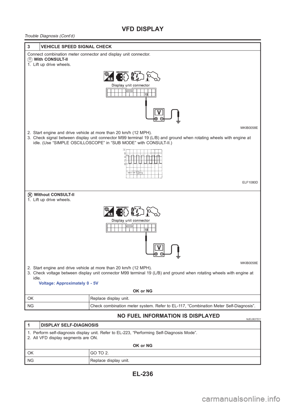
Connect combination meter connector and display unit connector.
With CONSULT-ll
1. Lift up drive wheels.
MKIB0058E
2. Start engine and drive vehicle at more than 20 km/h (12 MPH).
3. Check signal between display unit connector M99 terminal 19 (L/B) and ground when rotating wheels with engine at
idle. (Use “SIMPLE OSCILLOSCOPE” in “SUB MODE” with CONSULT-II.)
ELF1080D
Without CONSULT-ll
1. Lift up drive wheels.
MKIB0058E
2. Start engine and drive vehicle at more than 20 km/h (12 MPH).
3. Check voltage between display unit connector M99 terminal 19 (L/B) and ground when rotating wheels with engine at
idle.
Voltage: Approximately 0 - 5V
OK or NG
OK Replace display unit.
NG Check combination meter system. Refer to EL-117, “Combination Meter Self-Diagnosis”.
NO FUEL INFORMATION IS DISPLAYEDNJEL0637S11
1 DISPLAY SELF-DIAGNOSIS
1. Perform self-diagnosis display unit. Refer to EL-223, “Performing Self-Diagnosis Mode”.
2. All VFD display segments are ON.
OK or NG
OK GO TO 2.
NG Replace display unit.
VFD DISPLAY
Trouble Diagnosis (Cont’d)
EL-236
Page 2808 of 3189
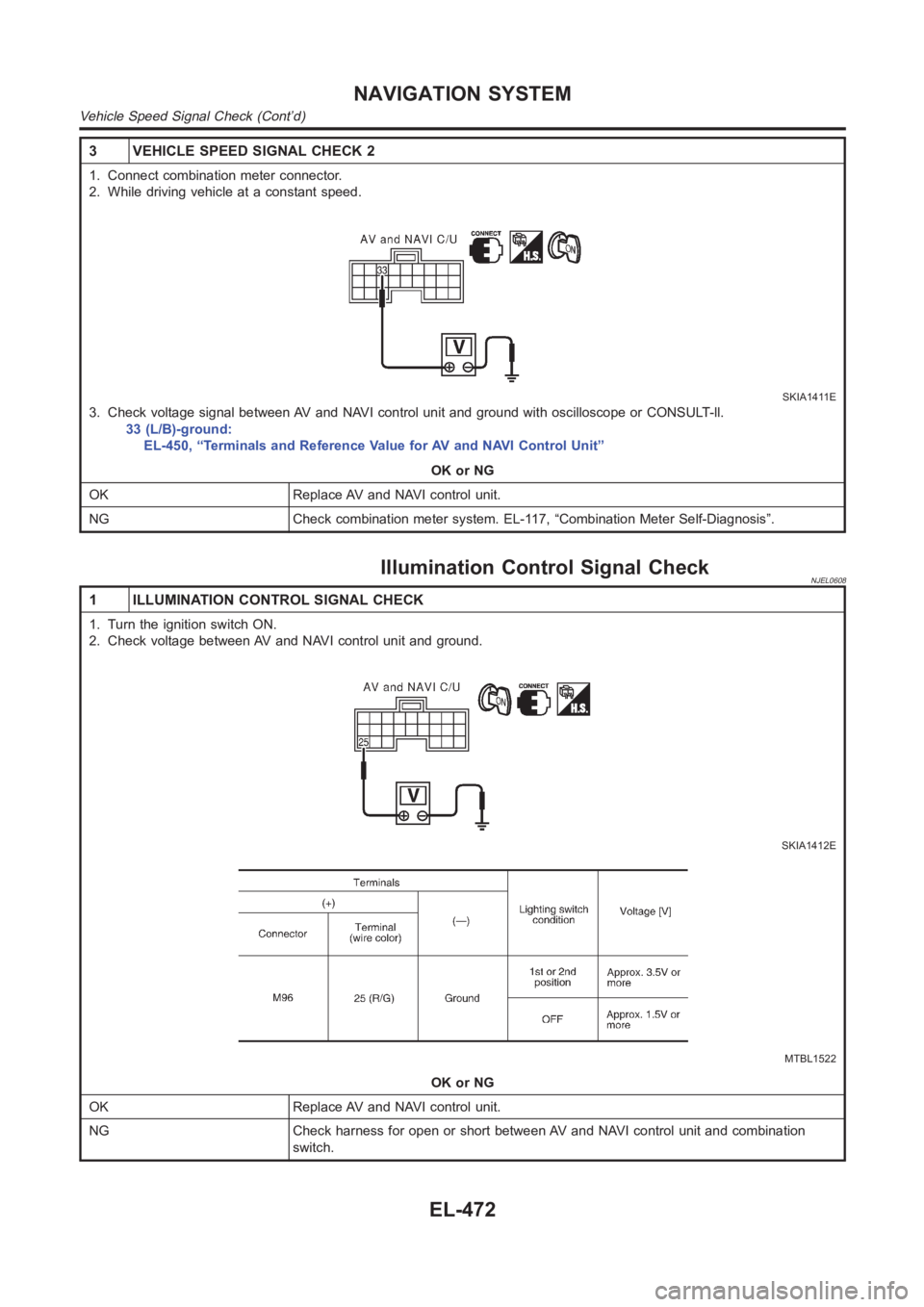
3 VEHICLE SPEED SIGNAL CHECK 2
1. Connect combination meter connector.
2. While driving vehicle at a constant speed.
SKIA1411E
3. Check voltage signal between AV and NAVI control unit and ground with oscilloscope or CONSULT-ll.
33 (L/B)-ground:
EL-450, “Terminals and Reference Value for AV and NAVI Control Unit”
OK or NG
OK Replace AV and NAVI control unit.
NG Check combination meter system. EL-117, “Combination Meter Self-Diagnosis”.
Illumination Control Signal CheckNJEL0608
1 ILLUMINATION CONTROL SIGNAL CHECK
1. Turn the ignition switch ON.
2. Check voltage between AV and NAVI control unit and ground.
SKIA1412E
MTBL1522
OK or NG
OK Replace AV and NAVI control unit.
NG Check harness for open or short between AV and NAVI control unit and combination
switch.
NAVIGATION SYSTEM
Vehicle Speed Signal Check (Cont’d)
EL-472