2003 NISSAN ALMERA N16 gauges
[x] Cancel search: gaugesPage 2461 of 3189
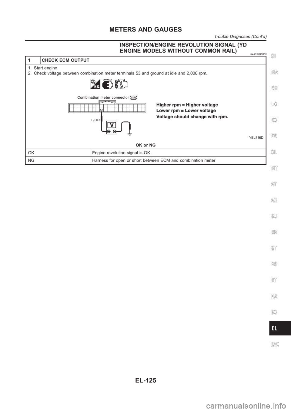
INSPECTION/ENGINE REVOLUTION SIGNAL (YD
ENGINE MODELS WITHOUT COMMON RAIL)
=NJEL0448S05
1 CHECK ECM OUTPUT
1. Start engine.
2. Check voltage between combination meter terminals 53 and ground at idleand 2,000 rpm.
YEL816D
OK or NG
OK Engine revolution signal is OK.
NG Harness for open or short between ECM and combination meter
GI
MA
EM
LC
EC
FE
CL
MT
AT
AX
SU
BR
ST
RS
BT
HA
SC
IDX
METERS AND GAUGES
Trouble Diagnoses (Cont’d)
EL-125
Page 2462 of 3189
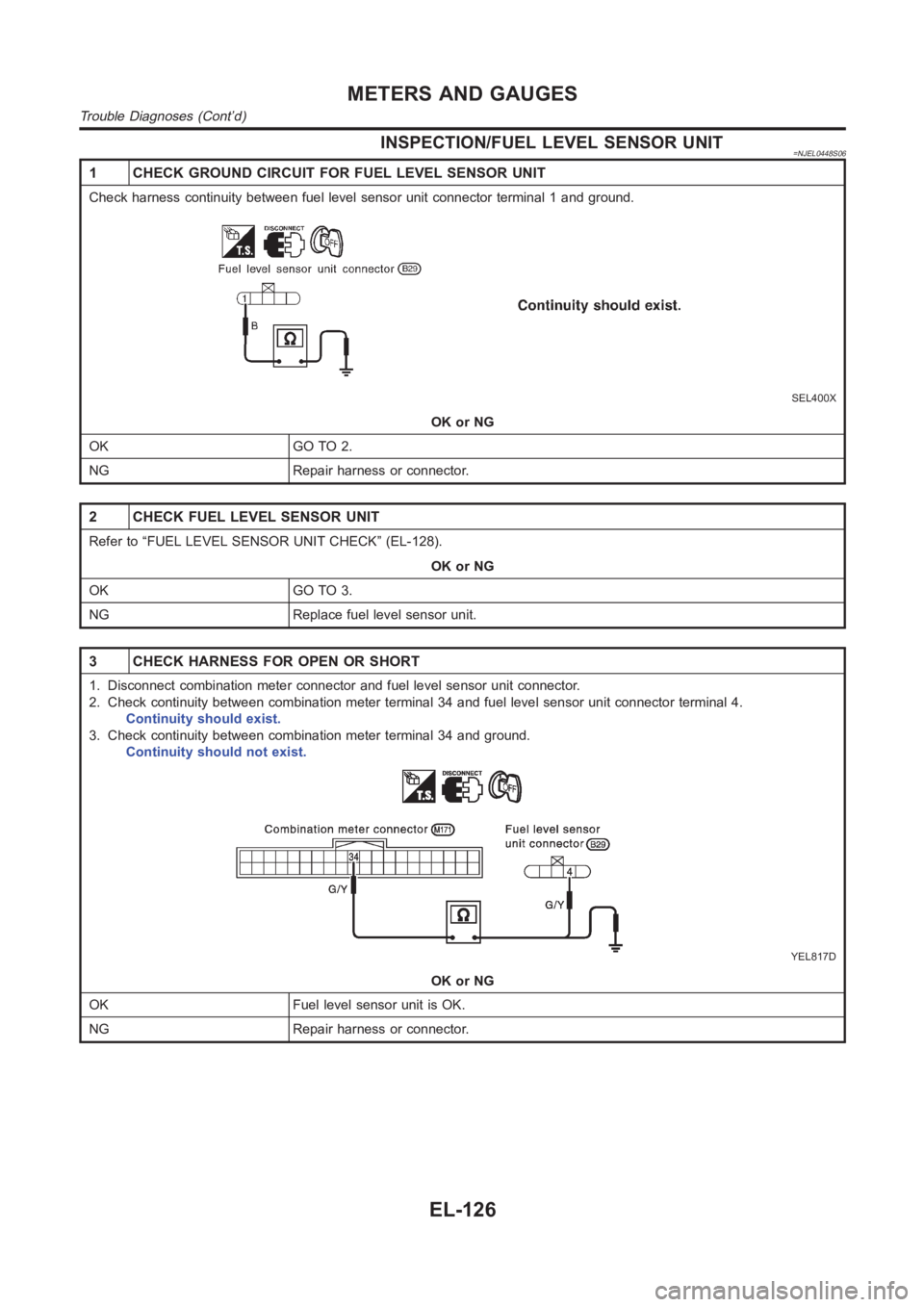
INSPECTION/FUEL LEVEL SENSOR UNIT=NJEL0448S06
1 CHECK GROUND CIRCUIT FOR FUEL LEVEL SENSOR UNIT
Check harness continuity between fuel level sensor unit connector terminal 1 and ground.
SEL400X
OK or NG
OK GO TO 2.
NG Repair harness or connector.
2 CHECK FUEL LEVEL SENSOR UNIT
Refer to “FUEL LEVEL SENSOR UNIT CHECK” (EL-128).
OK or NG
OK GO TO 3.
NG Replace fuel level sensor unit.
3 CHECK HARNESS FOR OPEN OR SHORT
1. Disconnect combination meter connector and fuel level sensor unit connector.
2. Check continuity between combination meter terminal 34 and fuel level sensor unit connector terminal 4.
Continuity should exist.
3. Check continuity between combination meter terminal 34 and ground.
Continuity should not exist.
YEL817D
OK or NG
OK Fuel level sensor unit is OK.
NG Repair harness or connector.
METERS AND GAUGES
Trouble Diagnoses (Cont’d)
EL-126
Page 2463 of 3189
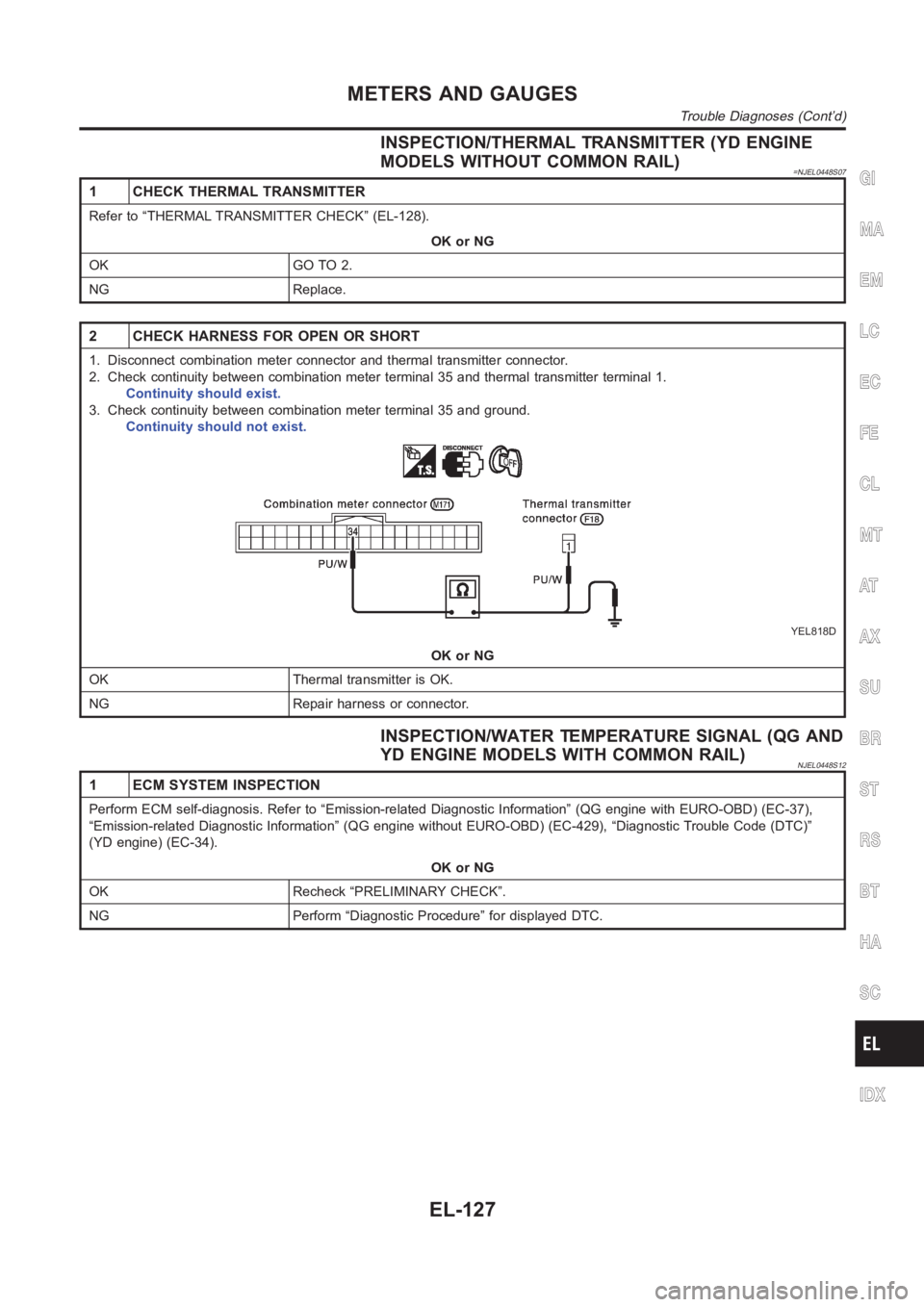
INSPECTION/THERMAL TRANSMITTER (YD ENGINE
MODELS WITHOUT COMMON RAIL)
=NJEL0448S07
1 CHECK THERMAL TRANSMITTER
Refer to “THERMAL TRANSMITTER CHECK” (EL-128).
OK or NG
OK GO TO 2.
NG Replace.
2 CHECK HARNESS FOR OPEN OR SHORT
1. Disconnect combination meter connector and thermal transmitter connector.
2. Check continuity between combination meter terminal 35 and thermal transmitter terminal 1.
Continuity should exist.
3. Check continuity between combination meter terminal 35 and ground.
Continuity should not exist.
YEL818D
OK or NG
OK Thermal transmitter is OK.
NG Repair harness or connector.
INSPECTION/WATER TEMPERATURE SIGNAL (QG AND
YD ENGINE MODELS WITH COMMON RAIL)
NJEL0448S12
1 ECM SYSTEM INSPECTION
Perform ECM self-diagnosis. Refer to “Emission-related Diagnostic Information” (QG engine with EURO-OBD) (EC-37),
“Emission-related Diagnostic Information” (QG engine without EURO-OBD) (EC-429), “Diagnostic Trouble Code (DTC)”
(YD engine) (EC-34).
OK or NG
OK Recheck “PRELIMINARY CHECK”.
NG Perform “Diagnostic Procedure” for displayed DTC.
GI
MA
EM
LC
EC
FE
CL
MT
AT
AX
SU
BR
ST
RS
BT
HA
SC
IDX
METERS AND GAUGES
Trouble Diagnoses (Cont’d)
EL-127
Page 2464 of 3189
SEL498X
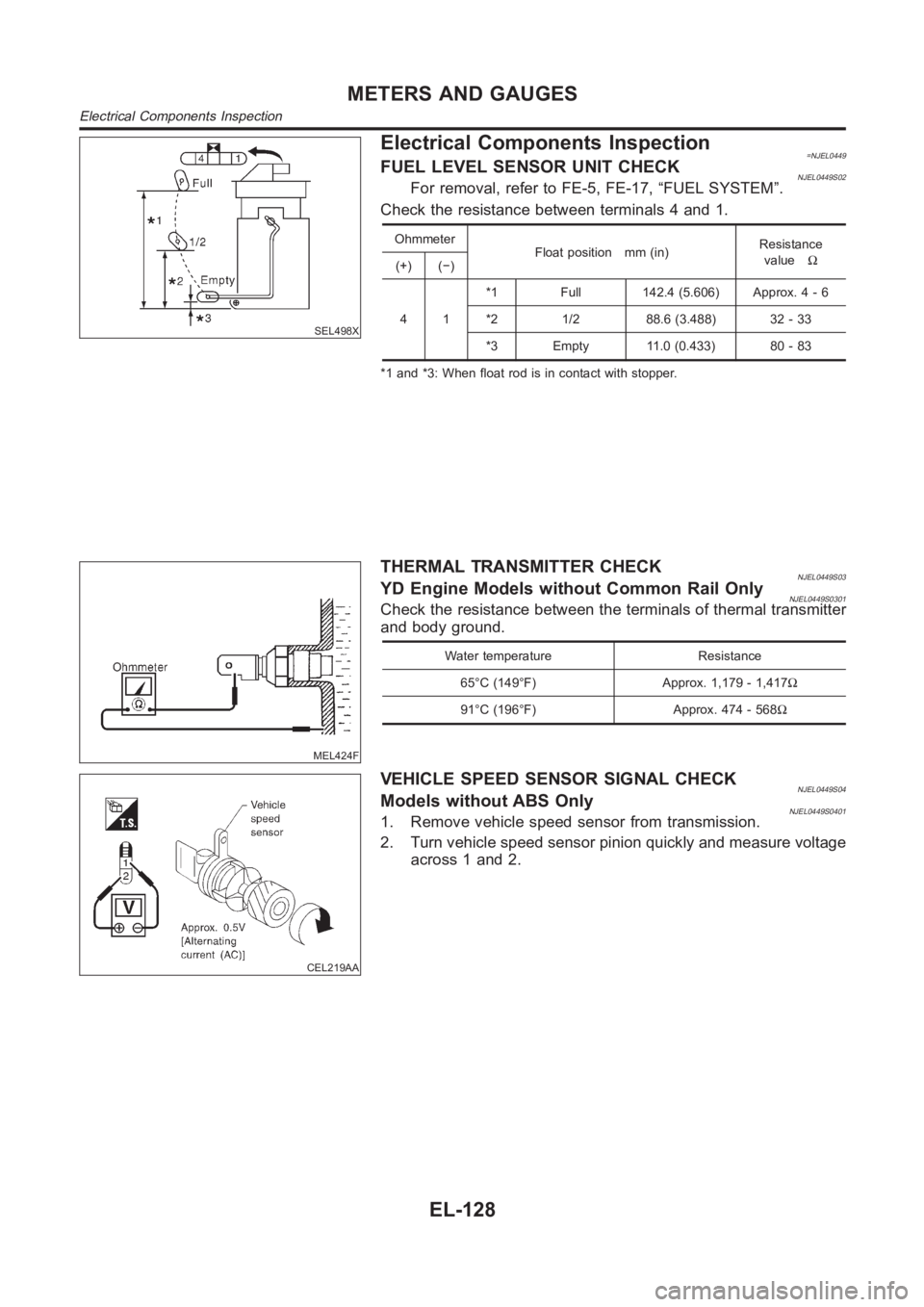
Electrical Components Inspection=NJEL0449FUEL LEVEL SENSOR UNIT CHECKNJEL0449S02For removal, refer to FE-5, FE-17, “FUEL SYSTEM”.
Check the resistance between terminals 4 and 1.
Ohmmeter
Float position mm (in)Resistance
valueΩ
(+) (−)
41*1 Full 142.4 (5.606) Approx. 4 - 6
*2 1/2 88.6 (3.488) 32 - 33
*3 Empty 11.0 (0.433) 80 - 83
*1 and *3: When float rod is in contact with stopper.
MEL424F
THERMAL TRANSMITTER CHECKNJEL0449S03YD Engine Models without Common Rail OnlyNJEL0449S0301Check the resistance between the terminals of thermal transmitter
and body ground.
Water temperature Resistance
65°C (149°F) Approx. 1,179 - 1,417Ω
91°C (196°F) Approx. 474 - 568Ω
CEL219AA
VEHICLE SPEED SENSOR SIGNAL CHECKNJEL0449S04Models without ABS OnlyNJEL0449S04011. Remove vehicle speed sensor from transmission.
2. Turn vehicle speed sensor pinion quickly and measure voltage
across 1 and 2.
METERS AND GAUGES
Electrical Components Inspection
EL-128
Page 2935 of 3189
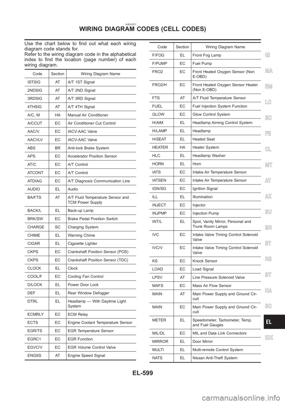
NJEL0311
Use the chart below to find out what each wiring
diagram code stands for.
Refer to the wiring diagram code in the alphabetical
index to find the location (page number) of each
wiring diagram.
Code Section Wiring Diagram Name
ISTSIG AT A/T 1ST Signal
2NDSIG AT A/T 2ND Signal
3RDSIG AT A/T 3RD Signal
4THSIG AT A/T 4TH Signal
A/C, M HA Manual Air Conditioner
A/CCUT EC Air Conditioner Cut Control
AAC/V EC IACV-AAC Valve
AACVLV EC IACV-AAC Valve
ABS BR Anti-lock Brake System
APS EC Accelerator Position Sensor
AT/C EC A/T Control
ATCONT EC A/T Control
ATDIAG EC A/T Diagnosis Communication Line
AUDIO EL Audio
BA/FTS AT A/T Fluid Temperature Sensor and
TCM Power Supply
BACK/L EL Back-up Lamp
BRK/SW EC Brake Pedal Position Switch
CHARGE SC Charging System
CHIME EL Warning Chime
CIGAR EL Cigarette Lighter
CKPS EC Crankshaft Position Sensor (POS)
CKPS EC Crankshaft Position Sensor (TDC)
CLOCK EL Clock
COOL/F EC Cooling Fan Control
D/LOCK EL Power Door Lock
DEF EL Rear Window Defogger
DTRL EL Headlamp — With Daytime Light
System
ECMRLY EC ECM Relay
ECTS EC Engine Coolant Temperature Sensor
EGR/TS EC EGR Temperature Sensor
EGRC1 EC EGR Function
EGVC/V EC EGR Volume Control Valve
ENGSS AT Engine Speed Signal
Code Section Wiring Diagram Name
F/FOG EL Front Fog Lamp
F/PUMP EC Fuel Pump
FRO2 EC Front Heated Oxygen Sensor (Non
E-OBD)
FRO2/H EC Front Heated Oxygen Sensor Heater
(Non E-OBD)
FTS AT A/T Fluid Temperature Sensor
FUEL EC Fuel Injection System Function
GLOW EC Glow Control System
H/AIM EL Headlamp Aiming Control System
H/LAMP EL Headlamp
H/SEAT EL Heated Seat
HEATER HA Heater System
HLC EL Headlamp Washer
HORN EL Horn
IATS EC Intake Air Temperature Sensor
IATSEN EC Intake Air Temperature Sensor
IGN/SG EC Ignition Signal
ILL EL Illumination
INJECT EC Injector
INJPMP EC Injection Pump
INT/L EL Spot, Vanity Mirror, Personal and
Trunk Room Lamps
IVC EC Intake Valve Timing Control Solenoid
Valve
IVC/V EC Intake Valve Timing Control Solenoid
Valve
KS EC Knock Sensor
LOAD EC Load Signal
LPSV AT Line Pressure Solenoid Valve
MAFS EC Mass Air Flow Sensor
MAIN AT Main Power Supply and Ground Cir-
cuit
MAIN EC Main Power Supply and Ground Cir-
cuit
METER EL Speedometer, Tachometer, Temp.
and Fuel Gauges
MIL/DL EC MIL and Data Link Connectors
MIRROR EL Door Mirror
MULTI EL Multi-remote Control System
NATS EL Nissan Anti-Theft System
GI
MA
EM
LC
EC
FE
CL
MT
AT
AX
SU
BR
ST
RS
BT
HA
SC
IDX
WIRING DIAGRAM CODES (CELL CODES)
EL-599
Page 3179 of 3189
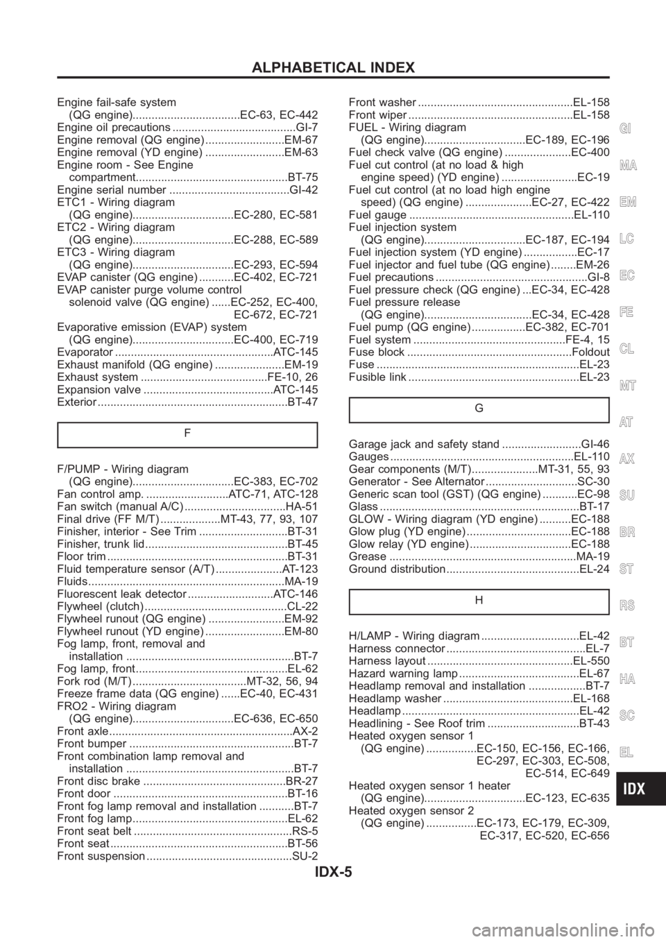
Engine fail-safe system
(QG engine)..................................EC-63, EC-442
Engine oil precautions .......................................GI-7
Engine removal (QG engine) .........................EM-67
Engine removal (YD engine) .........................EM-63
Engine room - See Engine
compartment................................................BT-75
Engine serial number ......................................GI-42
ETC1 - Wiring diagram
(QG engine)................................EC-280, EC-581
ETC2 - Wiring diagram
(QG engine)................................EC-288, EC-589
ETC3 - Wiring diagram
(QG engine)................................EC-293, EC-594
EVAP canister (QG engine) ...........EC-402, EC-721
EVAP canister purge volume control
solenoid valve (QG engine) ......EC-252, EC-400,
EC-672, EC-721
Evaporative emission (EVAP) system
(QG engine)................................EC-400, EC-719
Evaporator <0011001100110011001100110011001100110011001100110011001100110011001100110011001100110011001100110011001100110011001100110011001100110011001100110011001100110011001100110011001100110011001100110011001100
24>�7�C-145
Exhaust manifold (QG engine) ......................EM-19
Exhaust system ........................................FE-10, 26
Expansion valve .........................................ATC-145
Exterior <0011001100110011001100110011001100110011001100110011001100110011001100110011001100110011001100110011001100110011001100110011001100110011001100110011001100110011001100110011001100110011001100110011001100
110011001100110011[.....BT-47
F
F/PUMP - Wiring diagram
(QG engine)................................EC-383, EC-702
Fan control amp. ..........................ATC-71, ATC-128
Fan switch (manual A/C) ................................HA-51
Final drive (FF M/T) ...................MT-43, 77, 93, 107
Finisher, interior - See Trim ............................BT-31
Finisher, trunk lid.............................................BT- 4 5
Floor trim <0011001100110011001100110011001100110011001100110011001100110011001100110011001100110011001100110011001100110011001100110011001100110011001100110011001100110011001100110011001100110011001100110011001100
11001100110011[...BT-31
Fluid temperature sensor (A/T) .....................AT-123
Fluids<0011001100110011001100110011001100110011001100110011001100110011001100110011001100110011001100110011001100110011001100110011001100110011001100110011001100110011001100110011001100110011001100110011001100
11001100110011001100110011[.....MA-19
Fluorescent leak detector ...........................ATC-146
Flywheel (clutch) .............................................CL-22
Flywheel runout (QG engine) ........................EM-92
Flywheel runout (YD engine) .........................EM-80
Fog lamp, front, removal and
installation <0011001100110011001100110011001100110011001100110011001100110011001100110011001100110011001100110011001100110011001100110011001100110011001100110011001100110011001100110011001100110011001100110011001100
11[..BT-7
Fog lamp, front................................................EL-62
Fork rod (M/T) ....................................MT-32, 56, 94
Freeze frame data (QG engine) ......EC-40, EC-431
FRO2 - Wiring diagram
(QG engine)................................EC-636, EC-650
Front axle<0011001100110011001100110011001100110011001100110011001100110011001100110011001100110011001100110011001100110011001100110011001100110011001100110011001100110011001100110011001100110011001100110011001100
11001100110011[....AX-2
Front bumper <0011001100110011001100110011001100110011001100110011001100110011001100110011001100110011001100110011001100110011001100110011001100110011001100110011001100110011001100110011001100110011001100110011001100
110011[BT-7
Front combination lamp removal and
installation <0011001100110011001100110011001100110011001100110011001100110011001100110011001100110011001100110011001100110011001100110011001100110011001100110011001100110011001100110011001100110011001100110011001100
11[..BT-7
Front disc brake .............................................BR-27
Front door <0011001100110011001100110011001100110011001100110011001100110011001100110011001100110011001100110011001100110011001100110011001100110011001100110011001100110011001100110011001100110011001100110011001100
11001100110011[.BT-16
Front fog lamp removal and installation ...........BT-7
Front fog lamp.................................................EL-62
Front seat belt ..................................................RS-5
Front seat <0011001100110011001100110011001100110011001100110011001100110011001100110011001100110011001100110011001100110011001100110011001100110011001100110011001100110011001100110011001100110011001100110011001100
11001100110011[..BT-56
Front suspension ..............................................SU-2Front washer .................................................EL-158
Front wiper <0011001100110011001100110011001100110011001100110011001100110011001100110011001100110011001100110011001100110011001100110011001100110011001100110011001100110011001100110011001100110011001100110011001100
1100110028[L-158
FUEL - Wiring diagram
(QG engine)................................EC-189, EC-196
Fuel check valve (QG engine) .....................EC-400
Fuel cut control (at no load & high
engine speed) (YD engine) ........................EC-19
Fuel cut control (at no load high engine
speed) (QG engine) .....................EC-27, EC-422
Fuel gauge <0011001100110011001100110011001100110011001100110011001100110011001100110011001100110011001100110011001100110011001100110011001100110011001100110011001100110011001100110011001100110011001100110011001100
1100110028002f[-110
Fuel injection system
(QG engine)................................EC-187, EC-194
Fuel injection system (YD engine) .................EC-17
Fuel injector and fuel tube (QG engine) ........EM-26
Fuel precautions ................................................GI-8
Fuel pressure check (QG engine) ...EC-34, EC-428
Fuel pressure release
(QG engine)..................................EC-34, EC-428
Fuel pump (QG engine) .................EC-382, EC-701
Fuel system ................................................FE-4,15
Fuse block <0011001100110011001100110011001100110011001100110011001100110011001100110011001100110011001100110011001100110011001100110011001100110011001100110011001100110011001100110011001100110011001100110011001100
11001100290052[ldout
Fuse <0011001100110011001100110011001100110011001100110011001100110011001100110011001100110011001100110011001100110011001100110011001100110011001100110011001100110011001100110011001100110011001100110011001100
1100110011001100110011001100110011[.....EL-23
Fusible link <0011001100110011001100110011001100110011001100110011001100110011001100110011001100110011001100110011001100110011001100110011001100110011001100110011001100110011001100110011001100110011001100110011001100
110011[..EL-23
G
Garage jack and safety stand .........................GI-46
Gauges <0011001100110011001100110011001100110011001100110011001100110011001100110011001100110011001100110011001100110011001100110011001100110011001100110011001100110011001100110011001100110011001100110011001100
11001100110011001100110011[.EL-110
Gear components (M/T).....................MT-31, 55, 93
Generator - See Alternator .............................SC-30
Generic scan tool (GST) (QG engine) ...........EC-98
Glass <0011001100110011001100110011001100110011001100110011001100110011001100110011001100110011001100110011001100110011001100110011001100110011001100110011001100110011001100110011001100110011001100110011001100
110011001100110011001100110011[.....BT-17
GLOW - Wiring diagram (YD engine) ..........EC-188
Glow plug (YD engine) .................................EC-188
Glow relay (YD engine) ................................EC-188
Grease <0011001100110011001100110011001100110011001100110011001100110011001100110011001100110011001100110011001100110011001100110011001100110011001100110011001100110011001100110011001100110011001100110011001100
11001100110011001100110011[..MA-19
Ground distribution..........................................EL-24
H
H/LAMP - Wiring diagram ...............................EL-42
Harness connector ............................................EL-7
Harness layout ..............................................EL-550
Hazard warning lamp ......................................EL-67
Headlamp removal and installation ..................BT-7
Headlamp washer .........................................EL-168
Headlamp <0011001100110011001100110011001100110011001100110011001100110011001100110011001100110011001100110011001100110011001100110011001100110011001100110011001100110011001100110011001100110011001100110011001100
110011001100110011[.EL-42
Headlining - See Roof trim .............................BT-43
Heated oxygen sensor 1
(QG engine) ................EC-150, EC-156, EC-166,
EC-297, EC-303, EC-508,
EC-514, EC-649
Heated oxygen sensor 1 heater
(QG engine)................................EC-123, EC-635
Heated oxygen sensor 2
(QG engine) ................EC-173, EC-179, EC-309,
EC-317, EC-520, EC-656
GI
MA
EM
LC
EC
FE
CL
MT
AT
AX
SU
BR
ST
RS
BT
HA
SC
EL
ALPHABETICAL INDEX
IDX-5