2003 NISSAN ALMERA N16 ec-49
[x] Cancel search: ec-49Page 926 of 3189
![NISSAN ALMERA N16 2003 Electronic Repair Manual EC-596
[QG (WITHOUT EURO-OBD)]
DTC P1217 ENGINE OVER TEMPERATURE
DTC P1217 ENGINE OVER TEMPERATURE
PFP:00000
System DescriptionEBS00KJ1
NOTE:
If DTC P1217 is displayed with DTC U1000, U1001, first per NISSAN ALMERA N16 2003 Electronic Repair Manual EC-596
[QG (WITHOUT EURO-OBD)]
DTC P1217 ENGINE OVER TEMPERATURE
DTC P1217 ENGINE OVER TEMPERATURE
PFP:00000
System DescriptionEBS00KJ1
NOTE:
If DTC P1217 is displayed with DTC U1000, U1001, first per](/manual-img/5/57350/w960_57350-925.png)
EC-596
[QG (WITHOUT EURO-OBD)]
DTC P1217 ENGINE OVER TEMPERATURE
DTC P1217 ENGINE OVER TEMPERATURE
PFP:00000
System DescriptionEBS00KJ1
NOTE:
If DTC P1217 is displayed with DTC U1000, U1001, first perform the trouble diagnosis for DTC U1000,
U1001. Refer to EC-492, "
DTC U1000, U1001 CAN COMMUNICATION LINE" .
COOLING FAN CONTROL
*1: The ECM determines the start signal status by the signals of engine speed and battery voltage.
*2: These signals are sent to the ECM through CAN communication line.
The ECM controls the cooling fan corresponding to the vehicle speed, engine coolant temperature, refrigerant
pressure, and air conditioner ON signal. The control system has 2-step control [ON/OFF].
The ECM sends a cooling fan control signal to the smart entrance control unit through CAN communication
line, and the smart entrance control unit controls cooling fan relay.
OPERATION
CONSULT-II Reference Value in Data Monitor ModeEBS00KJ2
Specification data are reference values.
Sensor Input Signal to ECM ECM Function Actuator
Crankshaft position sensor (POS)
Camshaft position sensor (PHASE)Engine speed
*1
Cooling fan
controlCooling fan relay Battery
Battery voltage
*1
Vehicle speed signal
Vehicle speed*2
Engine coolant temperature sensor Engine coolant temperature
Air conditioner switch
Air conditioner “ON” signal
*2
Refrigerant pressure sensor Refrigerant pressure
MBIB0036E
MONITOR ITEM CONDITION SPECIFICATION
AIR COND SIG
●Engine: After warming up, idle
the engineAir conditioner switch: OFF OFF
Air conditioner switch: ON
(Compressor operates.)ON
COOLING FAN
●Engine: After warming up, idle
the engine
●Air conditioner switch: OFFEngine coolant temperature is 99°C
(210°F) or lessOFF
Engine coolant temperature is 100°C
(212°F) or moreON
Page 1007 of 3189
![NISSAN ALMERA N16 2003 Electronic Repair Manual VSS
EC-677
[QG (WITHOUT EURO-OBD)]
C
D
E
F
G
H
I
J
K
L
MA
EC
VSSPFP:32702
DescriptionEBS00KLE
NOTE:
If DTC U1000 or U1001 is displayed, first perform the trouble diagnosis for DTC U1000, U1001. Refer NISSAN ALMERA N16 2003 Electronic Repair Manual VSS
EC-677
[QG (WITHOUT EURO-OBD)]
C
D
E
F
G
H
I
J
K
L
MA
EC
VSSPFP:32702
DescriptionEBS00KLE
NOTE:
If DTC U1000 or U1001 is displayed, first perform the trouble diagnosis for DTC U1000, U1001. Refer](/manual-img/5/57350/w960_57350-1006.png)
VSS
EC-677
[QG (WITHOUT EURO-OBD)]
C
D
E
F
G
H
I
J
K
L
MA
EC
VSSPFP:32702
DescriptionEBS00KLE
NOTE:
If DTC U1000 or U1001 is displayed, first perform the trouble diagnosis for DTC U1000, U1001. Refer to
EC-492, "
DTC U1000, U1001 CAN COMMUNICATION LINE" .
The vehicle speed signal is sent from vehicle speed sensor (models with ABS) or ABS actuator and electric
unit (control unit) (models with ABS) to combination meter. The combination meter then sends a signal to the
ECM through CAN communication line.
Diagnostic ProcedureEBS00KLF
1.CHECK VEHICLE SPEED SIGNAL OVERALL FUNCTION
With CONSULT-II
1. Lift up the vehicle.
2. Start engine.
3. Select “VHCL SPEED SE” in “DATA MONITOR” mode with
CONSULT-II.
4. Make sure that “VHCL SPEED SE” indication exceeds 10 km/h
(6 MPH) when rotating wheels with suitable gear position.
Without CONSULT-II
1. Lift up the vehicle.
2. Start engine.
3. Read vehicle speed with combination meter.
Make sure that vehicle speed indication exceeds 10 km/h (6 MPH) when rotating wheels with suitable
gear position.
OK or NG
OK >>INSPECTION END
NG >> GO TO 2.
2.CHECK DTC WITH VEHICLE SPEED SONSOR (MODELS WITHOUT ABS) OR ABS ACTUATOR AND
ELECTRIC UNIT (CONTROL UNIT) (MODELS WITH ABS)
Refer to EL-123 (models without ABS) or EL-124 (models with ABS).
OK or NG
OK >> GO TO 2.
NG >> Repair or replace.
3.CHECK COMBINATION METER
Check combination meter function.
Refer to EL-112.
>>INSPECTION END
SEF196Y
Page 1103 of 3189

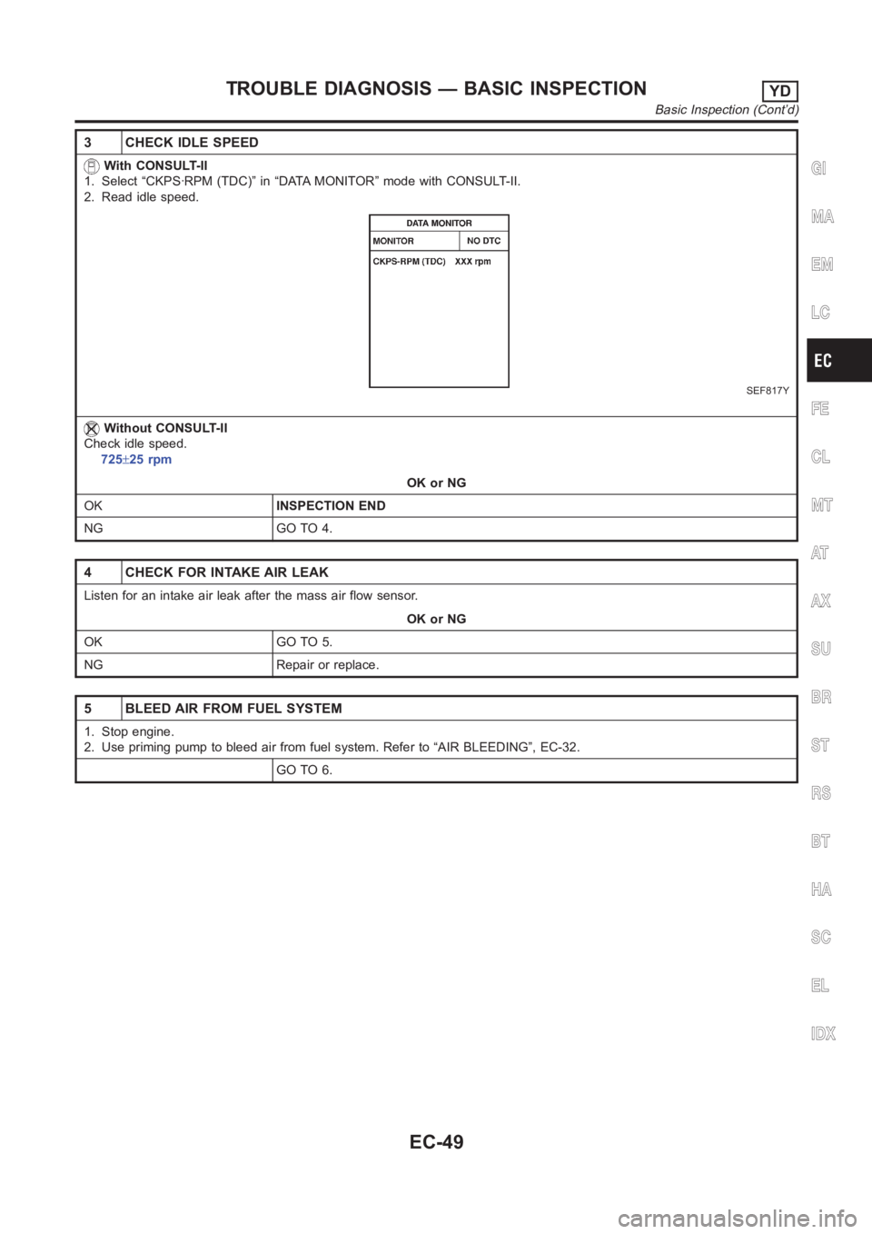
3 CHECK IDLE SPEED
With CONSULT-II
1. Select “CKPS·RPM (TDC)” in “DATA MONITOR” mode with CONSULT-II.
2. Read idle speed.
SEF817Y
Without CONSULT-II
Check idle speed.
725±25 rpm
OK or NG
OKINSPECTION END
NG GO TO 4.
4 CHECK FOR INTAKE AIR LEAK
Listen for an intake air leak after the mass air flow sensor.
OK or NG
OK GO TO 5.
NG Repair or replace.
5 BLEED AIR FROM FUEL SYSTEM
1. Stop engine.
2. Use priming pump to bleed air from fuel system. Refer to “AIR BLEEDING”, EC-32.
GO TO 6.
GI
MA
EM
LC
FE
CL
MT
AT
AX
SU
BR
ST
RS
BT
HA
SC
EL
IDX
TROUBLE DIAGNOSIS — BASIC INSPECTIONYD
Basic Inspection (Cont’d)
EC-49
Page 1497 of 3189
![NISSAN ALMERA N16 2003 Electronic Repair Manual ON BOARD DIAGNOSTIC SYSTEM DESCRIPTION
AT-41
[EURO-OBD]
D
E
F
G
H
I
J
K
L
MA
B
AT
Malfunction Indicator (MI)ECS007NR
1. The malfunction indicator lamp will light up when the ignition
switch NISSAN ALMERA N16 2003 Electronic Repair Manual ON BOARD DIAGNOSTIC SYSTEM DESCRIPTION
AT-41
[EURO-OBD]
D
E
F
G
H
I
J
K
L
MA
B
AT
Malfunction Indicator (MI)ECS007NR
1. The malfunction indicator lamp will light up when the ignition
switch](/manual-img/5/57350/w960_57350-1496.png)
ON BOARD DIAGNOSTIC SYSTEM DESCRIPTION
AT-41
[EURO-OBD]
D
E
F
G
H
I
J
K
L
MA
B
AT
Malfunction Indicator (MI)ECS007NR
1. The malfunction indicator lamp will light up when the ignition
switch is turned ON without the engine running. This is for
checking the lamp.
●If the malfunction indicator does not light up, refer to EC-397
or EC-715 .
(Or see MI & CONSULT-II in EC section. Refer to EC-49
, EC-
87 .
2. When the engine is started, the malfunction indicator should
turned OFF.
If the lamp remains ON, the on board diagnostic system has
detected an emission-related (EURO-OBD) malfunction. For
detail, refer to EC-36.
CONSULT-IIECS007NS
After performing “SELF-DIAGNOSTIC PROCEDURE (WITH CONSULT-II)” AT- 4 1 , place check marks for
results on the “DIAGNOSTIC WORKSHEET”, AT- 5 7
. Reference pages are provided following the items.
NOTICE:
1. The CONSULT-II electrically displays shift timing and lock-up timing (that is, operation timing of each sole-
noid valve).
Check for time difference between actual shift timing and the CONSULT-II display. If the difference is
noticeable, mechanical parts (except solenoid valves, sensors, etc.) may be malfunctioning. Check
mechanical parts using applicable diagnostic procedures.
2. Shift schedule (which implies gear position) displayed on CONSULT-II and that indicated in Service Man-
ual may differ slightly. This occurs because of the following reasons:
–Actual shift schedule has more or less tolerance or allowance,
–Shift schedule indicated in Service Manual refers to the point where shifts start, and
–Gear position displayed on CONSULT-II indicates the point where shifts are completed.
3. Shift solenoid valve “A” or “B” is displayed on CONSULT-II at the start of shifting. Gear position is dis-
played upon completion of shifting (which is computed by TCM).
4. Additional CONSULT-II information can be found in the Operation Manual supplied with the CONSULT-II
unit.
SELF-DIAGNOSTIC PROCEDURE (WITH CONSULT-II)
1. Turn on CONSULT-II and touch “ENGINE” for EURO-OBD
detected items or touch “A/T” for TCM self-diagnosis.
If A/T is not displayed, check TCM power supply and ground cir-
cuit. Refer to AT- 1 0 6 , "
TCM Terminals and Reference Value" . If
result is NG, refer to EL-11, "POWER SUPPLY ROUTING".
2. Touch “SELF DIAGNOSIS”.
Display shows malfunction experienced since the last erasing
operation.
CONSULT-II performs “real time diagnosis”.
Also, any malfunction detected while in this mode will be dis-
played at real time.
SAT652J
SAT014K
SAT987J
Page 1506 of 3189
![NISSAN ALMERA N16 2003 Electronic Repair Manual AT-50
[EURO-OBD]
ON BOARD DIAGNOSTIC SYSTEM DESCRIPTION
DTC WORK SUPPORT MODE
Diagnostic Procedure Without CONSULT-IIECS007NT
EURO-OBD SELF-DIAGNOSTIC PROCEDURE (WITH GST)
Refer to EC-97, "Generic NISSAN ALMERA N16 2003 Electronic Repair Manual AT-50
[EURO-OBD]
ON BOARD DIAGNOSTIC SYSTEM DESCRIPTION
DTC WORK SUPPORT MODE
Diagnostic Procedure Without CONSULT-IIECS007NT
EURO-OBD SELF-DIAGNOSTIC PROCEDURE (WITH GST)
Refer to EC-97, "Generic](/manual-img/5/57350/w960_57350-1505.png)
AT-50
[EURO-OBD]
ON BOARD DIAGNOSTIC SYSTEM DESCRIPTION
DTC WORK SUPPORT MODE
Diagnostic Procedure Without CONSULT-IIECS007NT
EURO-OBD SELF-DIAGNOSTIC PROCEDURE (WITH GST)
Refer to EC-97, "Generic Scan Tool (GST) Function" .
EURO-OBD SELF-DIAGNOSTIC PROCEDURE (NO TOOLS)
Refer to EC-49, "Malfunction Indicator (MI)" .
DTC work support item Description Check items (Possible cause)
1ST GR FNCTN P0731Following items for “A/T 1st gear function (P0731)” can be con-
firmed.
●Self-diagnosis status (whether the diagnosis is being conducted
or not)
●Self-diagnosis result (OK or NG)
●Shift solenoid valve A
●Shift solenoid valve B
●Each clutch
●Hydraulic control circuit
2ND GR FNCTN P0732Following items for “A/T 2nd gear function (P0732)” can be con-
firmed.
●Self-diagnosis status (whether the diagnosis is being conducted
or not)
●Self-diagnosis result (OK or NG)
●Shift solenoid valve B
●Each clutch
●Hydraulic control circuit
3RD GR FNCTN P0733Following items for “A/T 3rd gear function (P0733)” can be con-
firmed.
●Self-diagnosis status (whether the diagnosis is being conducted
or not)
●Self-diagnosis result (OK or NG)
●Shift solenoid valve A
●Each clutch
●Hydraulic control circuit
4TH GR FNCTN P0734Following items for “A/T 4th gear function (P0734)” can be con-
firmed.
●Self-diagnosis status (whether the diagnosis is being conducted
or not)
●Self-diagnosis result (OK or NG)
●Shift solenoid valve A
●Shift solenoid valve B
●Overrun clutch solenoid valve
●Line pressure solenoid valve
●Each clutch
●Hydraulic control circuit
Page 2851 of 3189

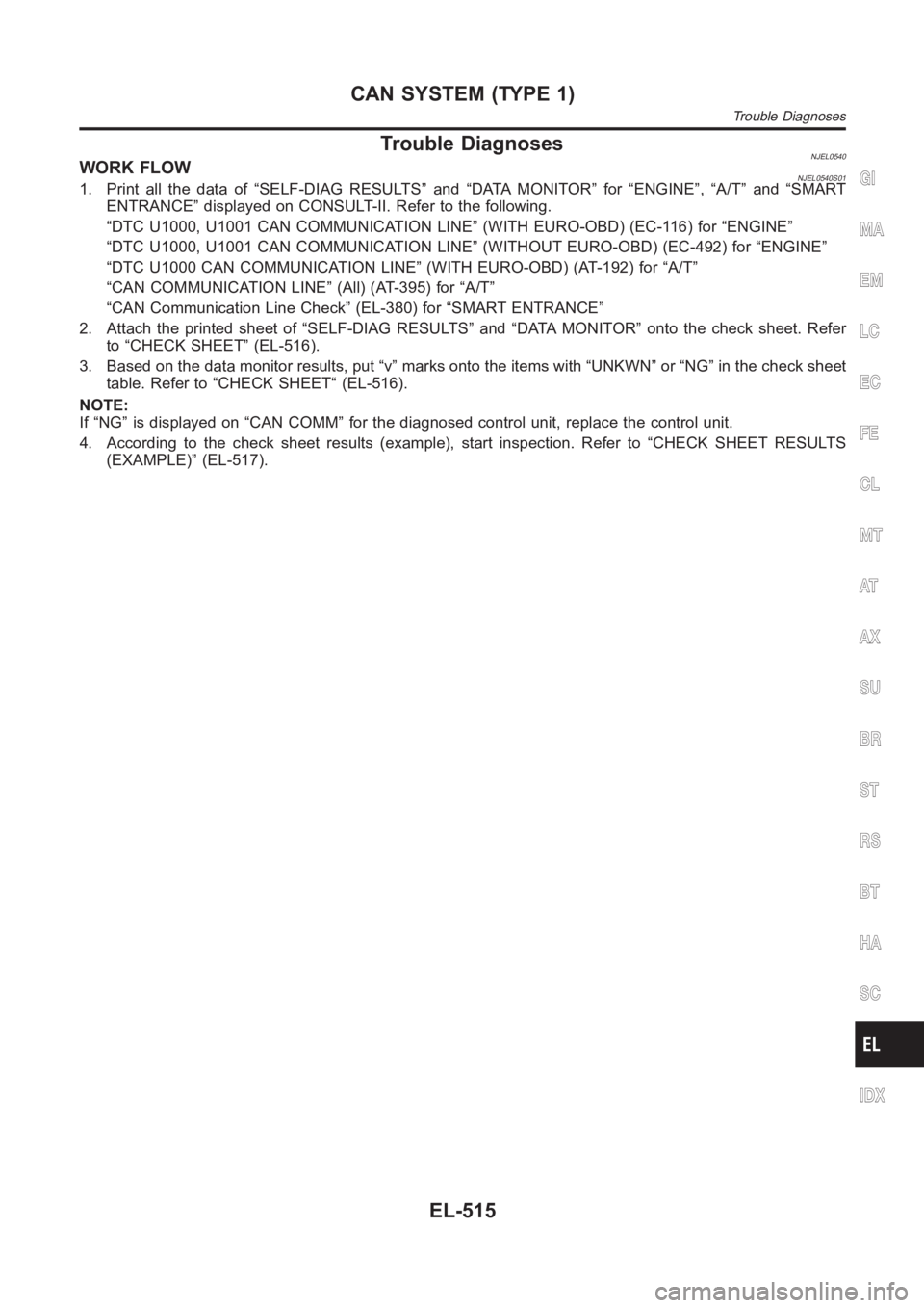
Trouble DiagnosesNJEL0540WORK FLOWNJEL0540S011. Print all the data of “SELF-DIAG RESULTS” and “DATA MONITOR” for “ENGINE”, “A/T” and “SMART
ENTRANCE” displayed on CONSULT-II. Refer to the following.
“DTC U1000, U1001 CAN COMMUNICATION LINE” (WITH EURO-OBD) (EC-116) for “ENGINE”
“DTC U1000, U1001 CAN COMMUNICATION LINE” (WITHOUT EURO-OBD) (EC-492) for “ENGINE”
“DTC U1000 CAN COMMUNICATION LINE” (WITH EURO-OBD) (AT-192) for “A/T”
“CAN COMMUNICATION LINE” (All) (AT-395) for “A/T”
“CAN Communication Line Check” (EL-380) for “SMART ENTRANCE”
2. Attach the printed sheet of “SELF-DIAG RESULTS” and “DATA MONITOR” ontothe check sheet. Refer
to “CHECK SHEET” (EL-516).
3. Based on the data monitor results, put “v” marks onto the items with “UNKWN” or “NG” in the check sheet
table. Refer to “CHECK SHEET“ (EL-516).
NOTE:
If “NG” is displayed on “CAN COMM” for the diagnosed control unit, replace the control unit.
4. According to the check sheet results (example), start inspection. Refer to “CHECK SHEET RESULTS
(EXAMPLE)” (EL-517).GI
MA
EM
LC
EC
FE
CL
MT
AT
AX
SU
BR
ST
RS
BT
HA
SC
IDX
CAN SYSTEM (TYPE 1)
Trouble Diagnoses
EL-515
Page 2869 of 3189

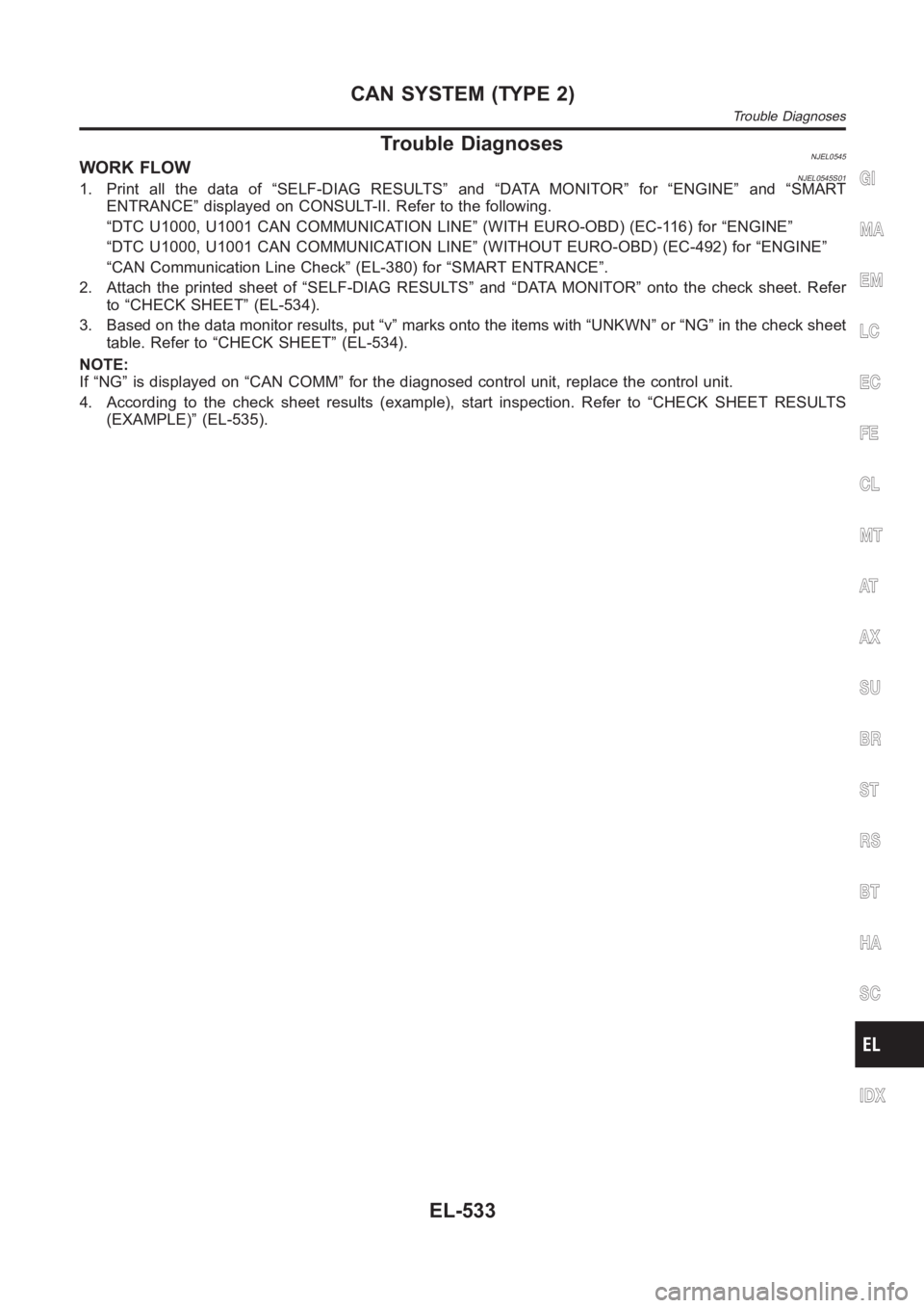
Trouble DiagnosesNJEL0545WORK FLOWNJEL0545S011. Print all the data of “SELF-DIAG RESULTS” and “DATA MONITOR” for “ENGINE” and “SMART
ENTRANCE” displayed on CONSULT-II. Refer to the following.
“DTC U1000, U1001 CAN COMMUNICATION LINE” (WITH EURO-OBD) (EC-116) for “ENGINE”
“DTC U1000, U1001 CAN COMMUNICATION LINE” (WITHOUT EURO-OBD) (EC-492) for “ENGINE”
“CAN Communication Line Check” (EL-380) for “SMART ENTRANCE”.
2. Attach the printed sheet of “SELF-DIAG RESULTS” and “DATA MONITOR” ontothe check sheet. Refer
to “CHECK SHEET” (EL-534).
3. Based on the data monitor results, put “v” marks onto the items with “UNKWN” or “NG” in the check sheet
table. Refer to “CHECK SHEET” (EL-534).
NOTE:
If “NG” is displayed on “CAN COMM” for the diagnosed control unit, replace the control unit.
4. According to the check sheet results (example), start inspection. Refer to “CHECK SHEET RESULTS
(EXAMPLE)” (EL-535).GI
MA
EM
LC
EC
FE
CL
MT
AT
AX
SU
BR
ST
RS
BT
HA
SC
IDX
CAN SYSTEM (TYPE 2)
Trouble Diagnoses
EL-533
Page 3176 of 3189

A
A/C air flow (manual A/C) ..............................HA-19
A/C air flow <0011001100110011001100110011001100110011001100110011001100110011001100110011001100110011001100110011001100110011001100110011001100110011001100110011001100110011001100110011001100110011001100110011001100
110024>�TC-27
A/C component layout (manual A/C) .............HA-17
A/C compressor clutch removal and
installation (manual A/C).............................HA-82
A/C compressor clutch removal and
installation ...............................................ATC-139
A/C compressor precaution (manual
A/C) <0011001100110011001100110011001100110011001100110011001100110011001100110011001100110011001100110011001100110011001100110011001100110011001100110011001100110011001100110011001100110011001100110011001100
1100110011001100110011001100110011[....HA-5
A/C compressor precaution ............................ATC-7
A/C compressor special service tool
(manual A/C) .................................................HA-9
A/C compressor special service tool ............ATC-11
A/C control linkage adjustment (manual
A/C) <0011001100110011001100110011001100110011001100110011001100110011001100110011001100110011001100110011001100110011001100110011001100110011001100110011001100110011001100110011001100110011001100110011001100
1100110011001100110011001100110011[..HA-42
A/C control operation (manual A/C) ...............HA-18
A/C diagnostic work flow (manual A/C)..........HA-34
A/C evaporator (manual A/C) .........................HA-87
A/C HFC134a (R134a) system precau-
tion (manual A/C) ..........................................HA-2
A/C HFC134a (R134a) system
precaution <0011001100110011001100110011001100110011001100110011001100110011001100110011001100110011001100110011001100110011001100110011001100110011001100110011001100110011001100110011001100110011001100110011001100
110024>�TC-4
A/C HFC134a (R134a) system service
procedure (manual A/C) .............................HA-77
A/C HFC134a (R134a) system service
procedure ................................................ATC-133
A/C HFC134a (R134a) system service
tools (manual A/C) ......................................HA-10
A/C HFC134a (R134a) system service
tools<0011001100110011001100110011001100110011001100110011001100110011001100110011001100110011001100110011001100110011001100110011001100110011001100110011001100110011001100110011001100110011001100110011001100
110011001100110011001100110011[.ATC-11
A/C HFC134a system service equip-
ment precaution (manual A/C)......................HA-6
A/C HFC134a system service equip-
ment precaution ..........................................ATC-7
A/C lubricant (R134a) (manual A/C) ..............HA-79
A/C lubricant (R134a) ...................................ATC-20
A/C lubrication oil .......................................ATC-150
A/C operational check (manual A/C)..............HA-35
A/C operational check ..................................ATC-51
A/C performance chart (manual A/C).............HA-69
A/C performance test diagnoses
(manual A/C) ...............................................HA-67
A/C performance test diagnoses ..................ATC-89
A/C relay (manual A/C) ..................................HA-65
A/C reray <0011001100110011001100110011001100110011001100110011001100110011001100110011001100110011001100110011001100110011001100110011001100110011001100110011001100110011001100110011001100110011001100110011001100
110011001100110024[TC-85
A/C self-diagnoses (auto A/C) ......................ATC-42
A/C service data specification (manual
A/C) <0011001100110011001100110011001100110011001100110011001100110011001100110011001100110011001100110011001100110011001100110011001100110011001100110011001100110011001100110011001100110011001100110011001100
1100110011001100110011001100110011[..HA-96
A/C service data specification ....................ATC-150
A/C switch (manual A/C) ................................HA-65
A/C system description (auto A/C) ...............ATC-22
A/C trouble diagnoses (auto A/C) ................ATC-29
A/C, A - Wiring diagram................................ATC-33
A/C, M - Wiring diagram (manual A/C) ..........HA-25
A/CCUT - Wiring diagram (YD engine) ........EC-212
A/T - Wiring diagram - AT - FTS ...................AT-120
A/T - Wiring diagram - AT - MAIN .................AT-341A/T - Wiring diagram - AT - PNP/SW ............AT-114
A/T - Wiring diagram - AT -
VSS A/T........................................AT-127, AT-346
A/T fluid checking ............................................AT-13
A/T fluid replacement ......................................AT-13
A/T fluid temperature sensor.........................AT-123
A/T shift lock system - Wiring diagram .........AT-400
A/T shift lock system .....................................AT-399
A/T trouble diagnoses ........................AT-56, AT-256
A/T Wiring diagram - AT -
ENG SS........................................AT-131, AT-386
A/T Wiring diagram AT - 1ST ........................AT-137
A/T Wiring diagram AT - 2ND .......................AT-143
A/T Wiring diagram AT - 3RD .......................AT-149
A/T Wiring diagram AT - 4TH ........................AT-155
A/T Wiring diagram AT - BA/FTS.....AT-198, AT-380
A/T Wiring diagram AT - LPSV ........AT-167, AT-391
A/T Wiring diagram AT - OVRCSV ..AT-190, AT-370
A/T Wiring diagram AT - SSV/A.......AT-174, AT-360
A/T Wiring diagram AT - SSV/B.......AT-179, AT-365
A/T Wiring diagram AT - TCV ..........AT-162, AT-375
A/T Wiring diagram AT - TPS ..........AT-185, AT-355
A/T Wiring diagrawm AT -
VSSMTR ......................................AT-204, AT-351
ABS (anti-lock brake system).........................BR-45
ABS - Wiring diagram ....................................BR-50
ABS sensor rotor ............................................AX-24
Accelerator control system .........................FE-3, 14
Accelerator pedal position (APP) sen-
sor (QG engine) ..........EC-212, EC-219, EC-346,
EC-538, EC-545, EC-619
Accelerator pedal released position
learning (QG engine)....................EC-31, EC-426
Accelerator position sensor
(YD engine).................................................EC-89
Air bag disposal..............................................RS-35
Air bag precautions ...........................................GI-3
Air bag <0011001100110011001100110011001100110011001100110011001100110011001100110011001100110011001100110011001100110011001100110011001100110011001100110011001100110011001100110011001100110011001100110011001100
11001100110011001100110011[...RS-20
Air bleeding (hydraulic clutch) ........................CL-10
Air bleeding for brake system ..........................BR-8
Air cleaner and air duct (QG engine) ............EM-14
Air cleaner filter (QG engine).........................EM-14
Air conditioner cut control
(QG engine)..................................EC-26, EC-421
Air conditioner cut control (YD engine) ..........EC-19
Air flow meter - See Mass air flow sen-
sor (QG engine) .........................EC-135, EC-497
Air flow meter - See Mass air flow sen-
sor (YD engine) ..........................................EC-78
Air mix door control linkage adjustment
(manual A/C) ...............................................HA-44
Air mix door control linkage
adjustment ................................ATC-65, ATC-127
Air mix. door motor.......................ATC-63, ATC-127
Air spoiler, rear................................................BT-47
Alternator <0011001100110011001100110011001100110011001100110011001100110011001100110011001100110011001100110011001100110011001100110011001100110011001100110011001100110011001100110011001100110011001100110011001100
1100110011[...SC-30
Ambient sensor...........ATC-101, ATC-103, ATC-116
Angular tightening application
(QG engine)..................................................EM-3
Angular tightening application
(YD engine) ..................................................EM-3
ALPHABETICAL INDEX
IDX-2