2003 NISSAN ALMERA N16 Resistor
[x] Cancel search: ResistorPage 1980 of 3189
![NISSAN ALMERA N16 2003 Electronic Repair Manual AT-524
[ALL]
SERVICE DATA AND SPECIFICATIONS (SDS)
Band Servo
ECS007U9
RETURN SPRING
Unit: mm (in)
*: Always check with the Parts Department for the latest parts information.
Removal and InstallationE NISSAN ALMERA N16 2003 Electronic Repair Manual AT-524
[ALL]
SERVICE DATA AND SPECIFICATIONS (SDS)
Band Servo
ECS007U9
RETURN SPRING
Unit: mm (in)
*: Always check with the Parts Department for the latest parts information.
Removal and InstallationE](/manual-img/5/57350/w960_57350-1979.png)
AT-524
[ALL]
SERVICE DATA AND SPECIFICATIONS (SDS)
Band Servo
ECS007U9
RETURN SPRING
Unit: mm (in)
*: Always check with the Parts Department for the latest parts information.
Removal and InstallationECS007UA
Unit: mm (in)
Shift Solenoid ValvesECS007UB
Solenoid ValvesECS007UC
A/T Fluid Temperature SensorECS007UD
Remarks: Specification data are reference values.
Revolution SensorECS007UE
Dropping ResistorECS007UF
Return spring Free length Outer diameter Part number*
2nd servo return spring 32.5 (1.280) 25.9 (1.020) 31605-31X20
OD servo return spring 38.52 (1.5165) 22.0 (0.866) 31605-31X21
Distance between end of converter housing and torque converter 21.1 (0.831) or more
Gear Solenoid A Solenoid B
1st ON ON
2nd OFF ON
3rd OFF OFF
4th ON OFF
Solenoid valve Resistance (Approx.) Terminal number
Shift solenoid A 20 - 30Ω2
Shift solenoid B 5 - 20Ω1
Ovr. clutch sol. 20 - 30Ω3
Line pres. sol. 2.5 - 5Ω4
T/conv. clutch sol. 5 - 20Ω5
Monitor item Condition Specification (Approximately)
A/T fluid temperature sensorCold [20°C (68°F)]
↓
Hot [80°C (176°F)]1.5V
↓
0.5V2.5 kΩ
↓
0.3 kΩ
Condition Judgement standard
When moving at 20 km/h (12 MPH), use the CONSULT-II pulse frequency measuring func-
tion.*1
CAUTION:
Connect the diagnosis data link cable to the vehicle diagnosis connector.
*1: A circuit tester cannot be used to test this item.150 Hz (Approx.)
When vehicle parks.Under 1.3V or over 4.5V
Resistance10 - 15Ω
Page 2471 of 3189
NEL796
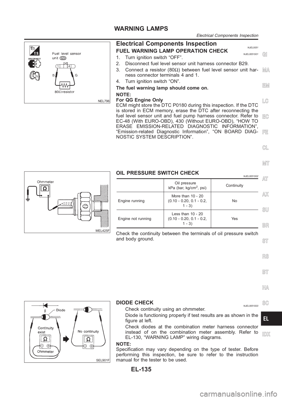
Electrical Components InspectionNJEL0051FUEL WARNING LAMP OPERATION CHECKNJEL0051S011. Turn ignition switch “OFF”.
2. Disconnect fuel level sensor unit harness connector B29.
3. Connect a resistor (80Ω) between fuel level sensor unit har-
ness connector terminals 4 and 1.
4. Turn ignition switch “ON”.
The fuel warning lamp should come on.
NOTE:
For QG Engine Only
ECM might store the DTC P0180 during this inspection. If the DTC
is stored in ECM memory, erase the DTC after reconnecting the
fuel level sensor unit and fuel pump harness connector. Refer to
EC-48 (With EURO-OBD), 430 (Without EURO-OBD), “HOW TO
ERASE EMISSION-RELATED DIAGNOSTIC INFORMATION”,
“Emission-related Diagnostic Information”, “ON BOARD DIAG-
NOSTIC SYSTEM DESCRIPTION”.
MEL425F
OIL PRESSURE SWITCH CHECKNJEL0051S02
Oil pressure
kPa (bar, kg/cm2, psi)Continuity
Engine runningMore than 10 - 20
(0.10 - 0.20, 0.1 - 0.2,
1-3)No
Engine not runningLess than 10 - 20
(0.10 - 0.20, 0.1 - 0.2,
1-3)Ye s
Check the continuity between the terminals of oil pressure switch
and body ground.
SEL901F
DIODE CHECKNJEL0051S03Check continuity using an ohmmeter.
Diode is functioning properly if test results are as shown in the
figure at left.
Check diodes at the combination meter harness connector
instead of on the combination meter assembly. Refer to
EL-130, “WARNING LAMP” wiring diagrams.
NOTE:
Specification may vary depending on the type of tester. Before
performing this inspection, be sure to refer to the instruction
manual for the tester to be used.
GI
MA
EM
LC
EC
FE
CL
MT
AT
AX
SU
BR
ST
RS
BT
HA
SC
IDX
WARNING LAMPS
Electrical Components Inspection
EL-135
Page 2983 of 3189
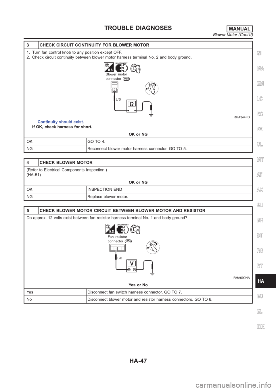
3 CHECK CIRCUIT CONTINUITY FOR BLOWER MOTOR
1. Turn fan control knob to any position except OFF.
2. Check circuit continuity between blower motor harness terminal No. 2 and body ground.
RHA344FD
Continuity should exist.
If OK, check harness for short.
OK or NG
OK GO TO 4.
NG Reconnect blower motor harness connector. GO TO 5.
4 CHECK BLOWER MOTOR
(Refer to Electrical Components Inspection.)
(HA-51)
OK or NG
OK INSPECTION END
NG Replace blower motor.
5 CHECK BLOWER MOTOR CIRCUIT BETWEEN BLOWER MOTOR AND RESISTOR
Do approx. 12 volts exist between fan resistor harness terminal No. 1 and body ground?
RHA699HA
YesorNo
Yes Disconnect fan switch harness connector. GO TO 7.
No Disconnect blower motor and resistor harness connectors. GO TO 6.
GI
MA
EM
LC
EC
FE
CL
MT
AT
AX
SU
BR
ST
RS
BT
SC
EL
IDX
TROUBLE DIAGNOSESMANUAL
Blower Motor (Cont’d)
HA-47
Page 2984 of 3189
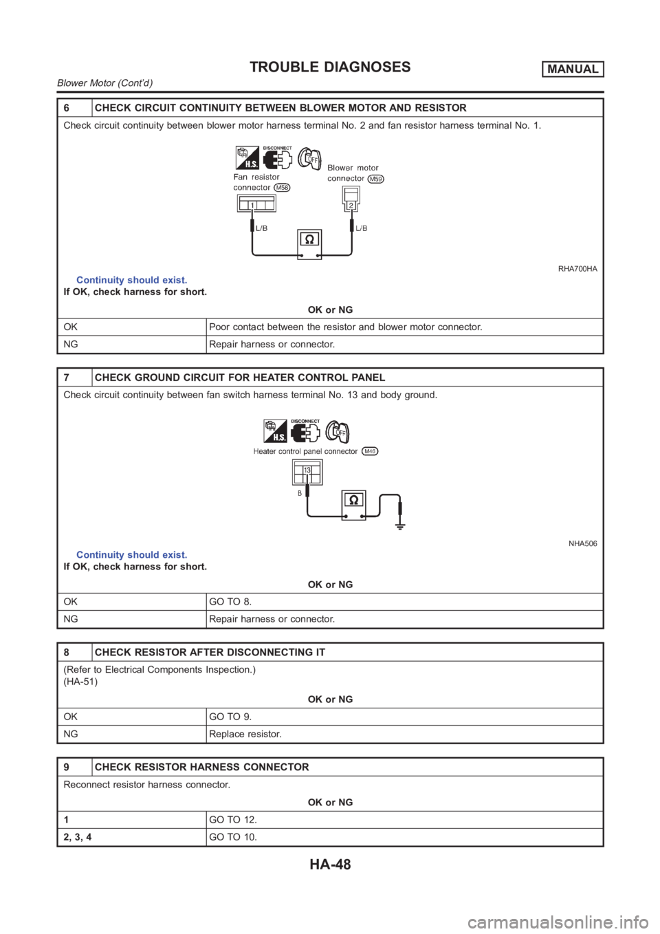
6 CHECK CIRCUIT CONTINUITY BETWEEN BLOWER MOTOR AND RESISTOR
Check circuit continuity between blower motor harness terminal No. 2 and fan resistor harness terminal No. 1.
RHA700HA
Continuity should exist.
If OK, check harness for short.
OK or NG
OK Poor contact between the resistor and blower motor connector.
NG Repair harness or connector.
7 CHECK GROUND CIRCUIT FOR HEATER CONTROL PANEL
Check circuit continuity between fan switch harness terminal No. 13 and body ground.
NHA506
Continuity should exist.
If OK, check harness for short.
OK or NG
OK GO TO 8.
NG Repair harness or connector.
8 CHECK RESISTOR AFTER DISCONNECTING IT
(Refer to Electrical Components Inspection.)
(HA-51)
OK or NG
OK GO TO 9.
NG Replace resistor.
9 CHECK RESISTOR HARNESS CONNECTOR
Reconnect resistor harness connector.
OK or NG
1GO TO 12.
2, 3, 4GO TO 10.
TROUBLE DIAGNOSESMANUAL
Blower Motor (Cont’d)
HA-48
Page 2985 of 3189
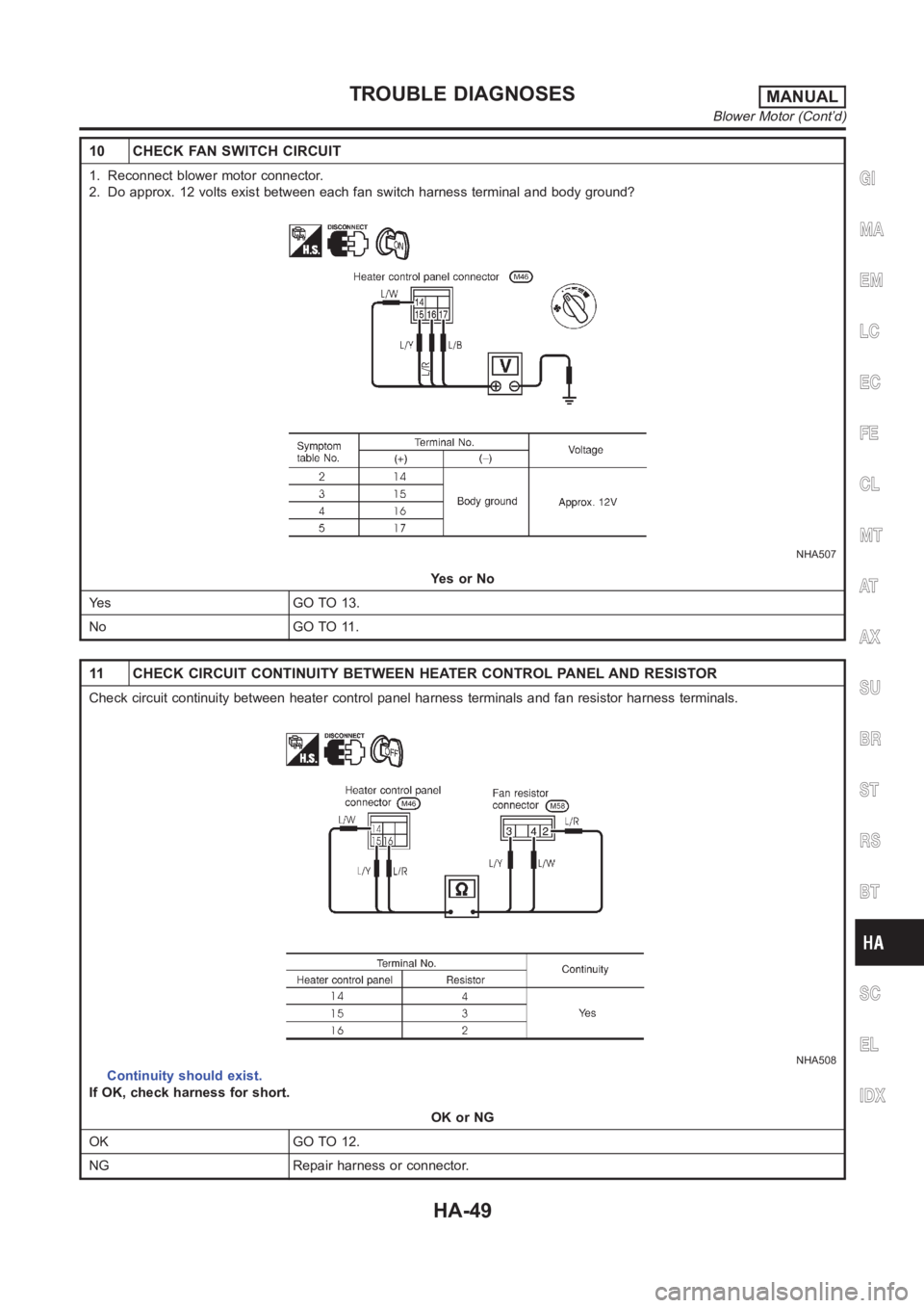
10 CHECK FAN SWITCH CIRCUIT
1. Reconnect blower motor connector.
2. Do approx. 12 volts exist between each fan switch harness terminal and body ground?
NHA507
YesorNo
Yes GO TO 13.
No GO TO 11.
11 CHECK CIRCUIT CONTINUITY BETWEEN HEATER CONTROL PANEL AND RESISTOR
Check circuit continuity between heater control panel harness terminalsand fan resistor harness terminals.
NHA508
Continuity should exist.
If OK, check harness for short.
OK or NG
OK GO TO 12.
NG Repair harness or connector.
GI
MA
EM
LC
EC
FE
CL
MT
AT
AX
SU
BR
ST
RS
BT
SC
EL
IDX
TROUBLE DIAGNOSESMANUAL
Blower Motor (Cont’d)
HA-49
Page 2987 of 3189
NHA386
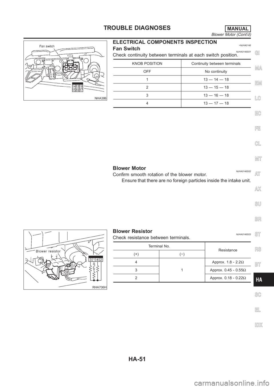
ELECTRICAL COMPONENTS INSPECTION=NJHA0146Fan SwitchNJHA0146S01Check continuity between terminals at each switch position.
KNOB POSITION Continuity between terminals
OFF No continuity
113—14—18
213—15—18
313—16—18
413—17—18
Blower MotorNJHA0146S02Confirm smooth rotation of the blower motor.
Ensure that there are no foreign particles inside the intake unit.
RHA706H
Blower ResistorNJHA0146S03Check resistance between terminals.
Terminal No.
Resistance
(+) (−)
4
1Approx. 1.8 - 2.2Ω
3 Approx. 0.45 - 0.55Ω
2 Approx. 0.18 - 0.22Ω
GI
MA
EM
LC
EC
FE
CL
MT
AT
AX
SU
BR
ST
RS
BT
SC
EL
IDX
TROUBLE DIAGNOSESMANUAL
Blower Motor (Cont’d)
HA-51
Page 3025 of 3189
RJIA0842E
3. Install the lower cover, then slide evaporator to forward.
4. Install the expansion valve from engine compartment.
Expansion valve mounting bolts
Tightening torque:
2.9 - 5.0 N·m (0.30 - 0.50 kg-m, 26 - 44 in-lb)
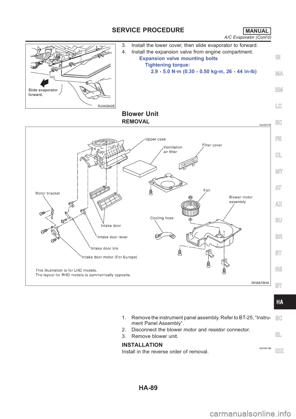
Blower Unit
REMOVALNJHA0195
RHA676HA
1. Remove the instrument panel assembly. Refer to BT-25, “Instru-
ment Panel Assembly”.
2. Disconnect the blower motor and resistor connector.
3. Remove blower unit.
INSTALLATIONNJHA0196Install in the reverse order of removal.
GI
MA
EM
LC
EC
FE
CL
MT
AT
AX
SU
BR
ST
RS
BT
SC
EL
IDX
SERVICE PROCEDUREMANUAL
A/C Evaporator (Cont’d)
HA-89
Page 3177 of 3189
Antenna - See Power antenna .....................EL-214
Anti-lock brake system - See ABS .................BR-45
Anti-lock brake system - Wiring
diagram <0011001100110011001100110011001100110011001100110011001100110011001100110011001100110011001100110011001100110011001100110011001100110011001100110011001100110011001100110011001100110011001100110011001100
1100110011001100110025[R-50
APPS1 - Wiring diagram
(QG engine)................................EC-221, EC-547
APPS2 - Wiring diagram
(QG engine)................................EC-348, EC-621
APPS3 - Wiring diagram
(QG engine)................................EC-214, EC-540
APS - Wiring diagram (YD engine) ................EC-89
Audio and A/C control removal and
installation - See Instrument panel .............BT-25
Audio <0011001100110011001100110011001100110011001100110011001100110011001100110011001100110011001100110011001100110011001100110011001100110011001100110011001100110011001100110011001100110011001100110011001100
110011001100110011001100110011[...EL-192
Auto air conditioner - Wiring diagram ..........ATC-33
Automatic amplifier .........................ATC-40, ATC-55
Automatic transaxle number............................GI-42
B
Back-up lamp switch (M/T) ............................MT-21
Back-up lamp <0011001100110011001100110011001100110011001100110011001100110011001100110011001100110011001100110011001100110011001100110011001100110011001100110011001100110011001100110011001100110011001100110011001100
28002f[-60
Ball joint (front) ...............................................SU-13
Basic inspection (QG engine) ..........EC-65, EC-444
Basic inspection (YD engine) .........................EC-48
Battery <0011001100110011001100110011001100110011001100110011001100110011001100110011001100110011001100110011001100110011001100110011001100110011001100110011001100110011001100110011001100110011001100110011001100
1100110011001100110011[......SC-3
Baulk ring (M/T) .................................MT-31, 55, 93
Blower motor (manual A/C) ............................HA-51
Blower motor ..................ATC-69, ATC-74, ATC-121
Blower resistor (manual A/C) .........................HA-51
Blower unit (manual A/C) ...............................HA-89
Blower unit <0011001100110011001100110011001100110011001100110011001100110011001100110011001100110011001100110011001100110011001100110011001100110011001100110011001100110011001100110011001100110011001100110011001100
24>�7�C-120
Board-on lift <0011001100110011001100110011001100110011001100110011001100110011001100110011001100110011001100110011001100110011001100110011001100110011001100110011001100110011001100110011001100110011001100110011001100
11[..GI-45
Body alignment ...............................................BT-74
Brake booster .................................................BR-20
Brake fluid change ...........................................BR-7
Brake fluid level and line check .......................BR-7
Brake hydraulic line ..........................................BR-9
Brake master cylinder ....................................BR-14
Brake pedal <0011001100110011001100110011001100110011001100110011001100110011001100110011001100110011001100110011001100110011001100110011001100110011001100110011001100110011001100110011001100110011001100110011001100
1100110025[R-12
Brake switch (QG engine) .............EC-361, EC-630
BRK/SW - Wiring diagram
(QG engine)................................EC-362, EC-631
Bulb specifications ........................................EL-598
Bumper, front <0011001100110011001100110011001100110011001100110011001100110011001100110011001100110011001100110011001100110011001100110011001100110011001100110011001100110011001100110011001100110011001100110011001100
11[.BT-7
Bumper, rear <0011001100110011001100110011001100110011001100110011001100110011001100110011001100110011001100110011001100110011001100110011001100110011001100110011001100110011001100110011001100110011001100110011001100
110025[T- 1 0
C
Camshaft (QG engine)...................................EM-32
Camshaft inspection (YD engine) ..................EM-49
Camshaft position sensor (PHASE)
(QG engine)................................EC-241, EC-563
CAN (Controller Area Network)........AT-110, AT-306
CAN (Controller Area Network) ....EL-509, 512, 530
CAN - Wiring diagram
(QG engine) ................................EC-118, EC-495
CAN - Wiring diagram ..........................EL-513, 531CAN communication
(QG engine) .....EC-117, EC-494, AT-110, AT-306
CAN communication .....................EL-509, 512, 530
Canister-See EVAP canister
(QG engine)................................EC-402, EC-721
CHARGE - Wiring diagram ............................SC-28
Charging system ............................................SC-27
CHIME - Wiring diagram...............................EL-139
CIGAR - Wiring diagram ...............................EL-171
Cigarette lighter.............................................EL-171
Circuit breaker.................................................EL-23
CKPS - Wiring diagram (YD engine) .............EC-99
Closed loop control (QG engine) .....EC-24, EC-419
Clutch cover <0011001100110011001100110011001100110011001100110011001100110011001100110011001100110011001100110011001100110011001100110011001100110011001100110011001100110011001100110011001100110011001100110011001100
110011[CL-22
Clutch disc <0011001100110011001100110011001100110011001100110011001100110011001100110011001100110011001100110011001100110011001100110011001100110011001100110011001100110011001100110011001100110011001100110011001100
1100110011[.CL-22
Clutch master cylinder ....................................CL-11
Clutch operating cylinder ................................CL-14
Clutch pedal <0011001100110011001100110011001100110011001100110011001100110011001100110011001100110011001100110011001100110011001100110011001100110011001100110011001100110011001100110011001100110011001100110011001100
110011[CL-10
Clutch release bearing .............................CL-17, 20
Clutch release mechanism .......................CL-17, 20
Clutch withdrawal lever ............................CL-17, 20
Coil spring (front)..............................................SU-9
Coil spring (rear) ............................................SU-21
Collision diagnosis..........................................RS-71
Combination lamp, rear, removal and
installation <0011001100110011001100110011001100110011001100110011001100110011001100110011001100110011001100110011001100110011001100110011001100110011001100110011001100110011001100110011001100110011001100110011001100
11[BT-47
Combination meter removal and instal-
lation - See Instrument panel ......................BT-25
Combination meter ........................................EL-110
Combination switch .........................................EL-39
Component Location (auto A/C) ...................ATC-30
Component Location (manual A/C) ................HA-21
Compression pressure (QG engine)..............EM-57
Compression pressure (YD engine) ................EM-9
Compressor clutch removal and instal-
lation (manual A/C) .....................................HA-82
Compressor clutch removal and
installation ...............................................ATC-139
Compressor precaution (manual A/C)..............HA-5
Compressor special service tool
(manual A/C) .................................................HA-9
Compressor special service tool ..................ATC-11
Condenser <0011001100110011001100110011001100110011001100110011001100110011001100110011001100110011001100110011001100110011001100110011001100110011001100110011001100110011001100110011001100110011001100110011001100
24>�7�&�-144
Connecting rod (QG engine) .........................EM-86
Connecting rod (YD engine) ..........................EM-72
Connecting rod bearing clearance
(QG engine)................................................EM-87
Connecting rod bearing clearance
(YD engine) ................................................EM-77
Connecting rod bushing clearance
(QG engine)................................................EM-87
Connecting rod bushing clearance
(YD engine) ................................................EM-79
Console box - See Instrument panel ..............BT-25
CONSULT for engine (QG engine) ..EC-88, EC-467
CONSULT for engine (YD engine) .................EC-39
Control lever (M/T) .........................................MT-29
Control unit .................................................ATC-114
Controller Area Network (CAN)........AT-110, AT-306
Controller Area Network (CAN) ....EL-509, 512, 530
Converter housing installation .........AT-412, AT-509
GI
MA
EM
LC
EC
FE
CL
MT
AT
AX
SU
BR
ST
RS
BT
HA
SC
EL
ALPHABETICAL INDEX
IDX-3