Page 251 of 3189
Removal and InstallationNJEM0071CAUTION:
When installing bearings, pistons, or other sliding parts,
lubricate contacting surfaces with new engine oil.
Place removed parts such as bearings and bearing caps
in their proper order and direction.
When installing connecting rod nuts, and main bearing
cap bolts, apply new engine oil to threads and seating
surfaces.
Do not allow any magnetic materials to contact the signal
plate of flywheel.
Do not remove the signal plate at back.
Do not place the signal plate side facing under.
Handle with care so as not to damage the signal plate
[especially four places on protrusions for signal of crank
position sensor (TDC sensor)].
DisassemblyNJEM0072PISTON AND CRANKSHAFTNJEM0072S011. Remove engine. Refer to “ENGINE ASSEMBLY”, “Removal
and Installation”, EM-63.
2. Place engine on a work stand.
a. Remove flywheel.
Hold ring gear with ring gear stopper (KV10105630,
KV10105610). Then, loosen securing bolts with TORX socket
(size: Q8 E20, Commercial Service Tool) and remove them.
As an alternative method, hold the crankshaft pulley with a
pulley holder (SST) to remove the flywheel.
JEM192G
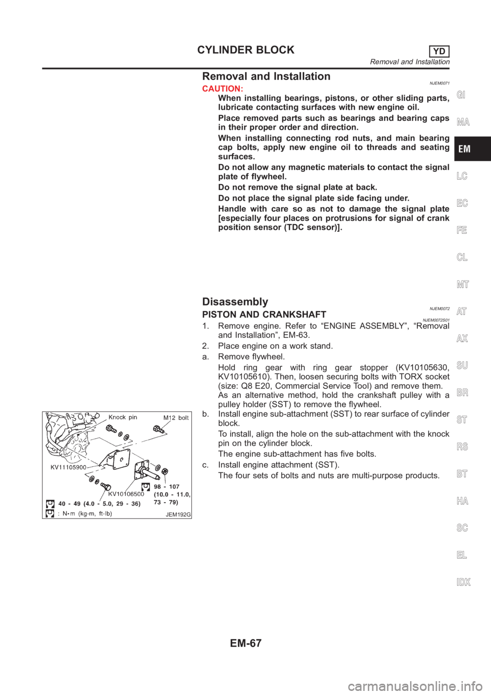
b. Install engine sub-attachment (SST) to rear surface of cylinder
block.
To install, align the hole on the sub-attachment with the knock
pin on the cylinder block.
The engine sub-attachment has five bolts.
c. Install engine attachment (SST).
The four sets of bolts and nuts are multi-purpose products.
GI
MA
LC
EC
FE
CL
MT
AT
AX
SU
BR
ST
RS
BT
HA
SC
EL
IDX
CYLINDER BLOCKYD
Removal and Installation
EM-67
Page 264 of 3189
JEM220G
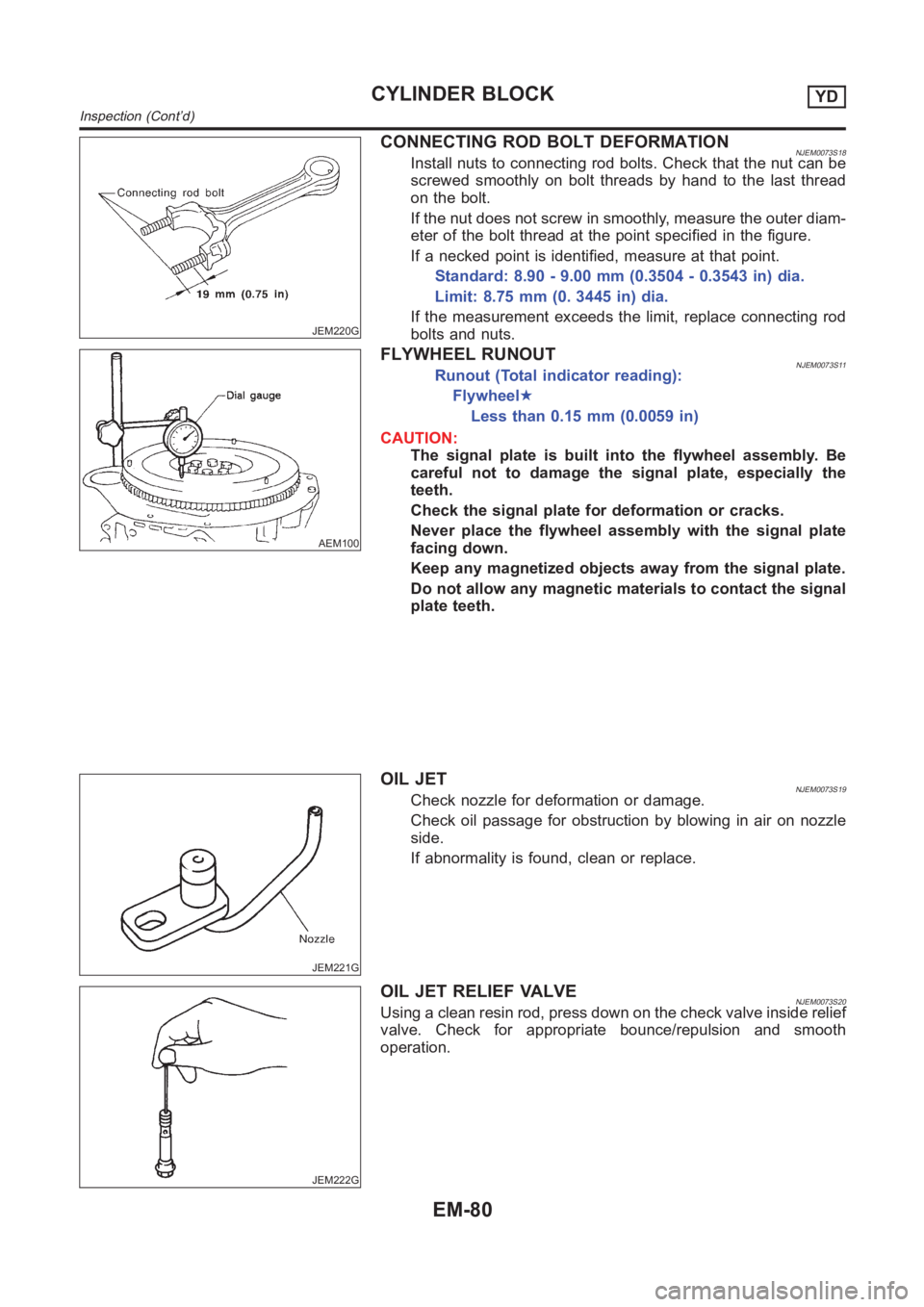
CONNECTING ROD BOLT DEFORMATIONNJEM0073S18Install nuts to connecting rod bolts. Check that the nut can be
screwed smoothly on bolt threads by hand to the last thread
on the bolt.
If the nut does not screw in smoothly, measure the outer diam-
eter of the bolt thread at the point specified in the figure.
If a necked point is identified, measure at that point.
Standard: 8.90 - 9.00 mm (0.3504 - 0.3543 in) dia.
Limit: 8.75 mm (0. 3445 in) dia.
If the measurement exceeds the limit, replace connecting rod
bolts and nuts.
AEM100
FLYWHEEL RUNOUTNJEM0073S11Runout (Total indicator reading):
Flywheel★
Less than 0.15 mm (0.0059 in)
CAUTION:
The signal plate is built into the flywheel assembly. Be
careful not to damage the signal plate, especially the
teeth.
Check the signal plate for deformation or cracks.
Never place the flywheel assembly with the signal plate
facing down.
Keep any magnetized objects away from the signal plate.
Do not allow any magnetic materials to contact the signal
plate teeth.
JEM221G
OIL JETNJEM0073S19Check nozzle for deformation or damage.
Check oil passage for obstruction by blowing in air on nozzle
side.
If abnormality is found, clean or replace.
JEM222G
OIL JET RELIEF VALVENJEM0073S20Using a clean resin rod, press down on the check valve inside relief
valve. Check for appropriate bounce/repulsion and smooth
operation.
CYLINDER BLOCKYD
Inspection (Cont’d)
EM-80
Page 268 of 3189
JEM233G
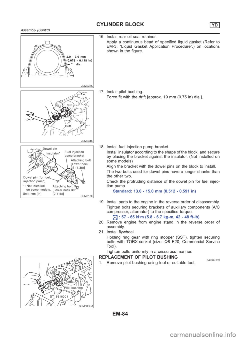
16. Install rear oil seal retainer.
Apply a continuous bead of specified liquid gasket (Refer to
EM-3, “Liquid Gasket Application Procedure”.) on locations
shown in the figure.
JEM234G
17. Install pilot bushing.
Force fit with the drift [approx. 19 mm (0.75 in) dia.].
SEM513G
18. Install fuel injection pump bracket.
Install insulator according to the shape of the block, and secure
by placing the bracket against the insulator. (Not installed on
some models)
Align the bracket with the dowel pins on the block to install.
The two bolts used for dowel pins have a longer shanks than
the other two.
Check the protruding distance of the dowel pin for fuel injec-
tion pump.
Standard: 13.0 - 15.0 mm (0.512 - 0.591 in)
19. Install parts to the engine in the reverse order of disassembly.
Tighten bolts securing brackets of auxiliary components (A/C
compressor, alternator) to the specified torque.
: 57 - 65 N·m (5.8 - 6.7 kg-m, 42 - 48 ft-lb)
20. Remove engine from engine stand in the reverse order of
assembly.
21. Install flywheel.
Holding ring gear with ring stopper (SST), tighten securing
bolts with TORX-socket (size: Q8 E20, Commercial Service
Tool).
Tighten bolts uniformly in a crisscross manner.
SEM500GA
REPLACEMENT OF PILOT BUSHINGNJEM0074S031. Remove pilot bushing using tool or suitable tool.
CYLINDER BLOCKYD
Assembly (Cont’d)
EM-84
Page 296 of 3189
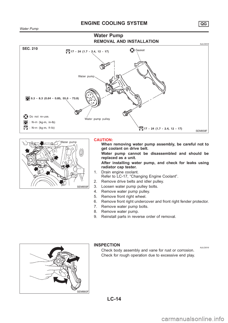
Water Pump
REMOVAL AND INSTALLATIONNJLC0018
SEM858F
SEM859F
CAUTION:
When removing water pump assembly, be careful not to
get coolant on drive belt.
Water pump cannot be disassembled and should be
replaced as a unit.
After installing water pump, and check for leaks using
radiator cap tester.
1. Drain engine coolant.
Refer to LC-17, “Changing Engine Coolant”.
2. Remove drive belts and idler pulley.
3. Loosen water pump pulley bolts.
4. Remove water pump pulley.
5. Remove front right wheel.
6. Remove front right undercover and front right fender protector.
7. Remove water pump bolts.
8. Remove water pump.
9. Reinstall parts in reverse order of removal.
SEM860F
INSPECTIONNJLC0019Check body assembly and vane for rust or corrosion.
Check for rough operation due to excessive end play.
ENGINE COOLING SYSTEMQG
Water Pump
LC-14
Page 1319 of 3189
SCL466-C
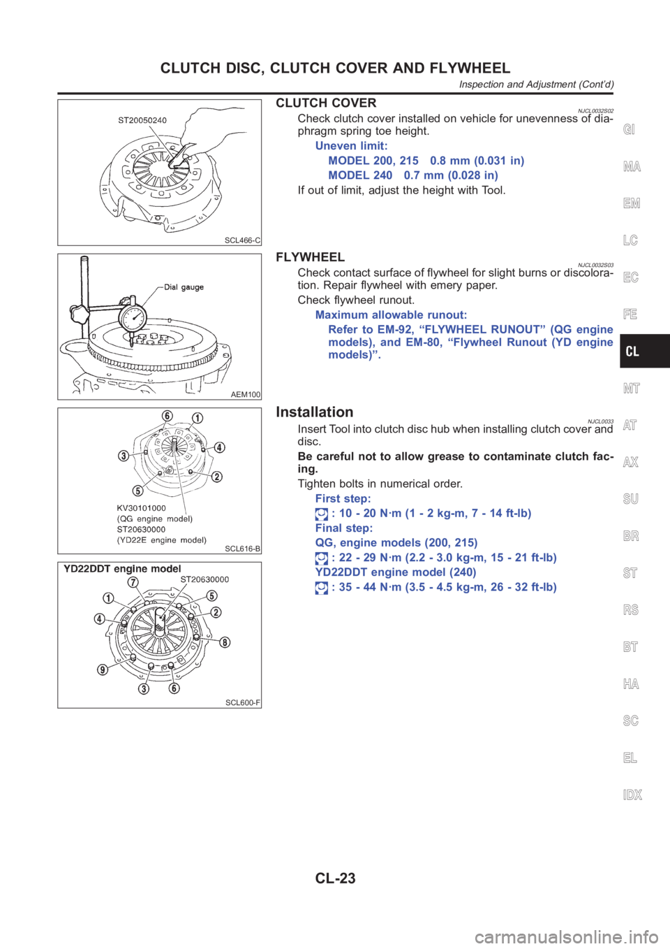
CLUTCH COVERNJCL0032S02Check clutch cover installed on vehicle for unevenness of dia-
phragm spring toe height.
Uneven limit:
MODEL 200, 215 0.8 mm (0.031 in)
MODEL 240 0.7 mm (0.028 in)
If out of limit, adjust the height with Tool.
AEM100
FLYWHEELNJCL0032S03Check contact surface of flywheel for slight burns or discolora-
tion. Repair flywheel with emery paper.
Check flywheel runout.
Maximum allowable runout:
Refer to EM-92, “FLYWHEEL RUNOUT” (QG engine
models), and EM-80, “Flywheel Runout (YD engine
models)”.
SCL616-B
SCL600-F
InstallationNJCL0033Insert Tool into clutch disc hub when installing clutch cover and
disc.
Be careful not to allow grease to contaminate clutch fac-
ing.
Tighten bolts in numerical order.
First step:
: 10 - 20 N·m (1 - 2 kg-m, 7 - 14 ft-lb)
Final step:
QG, engine models (200, 215)
: 22 - 29 N·m (2.2 - 3.0 kg-m, 15 - 21 ft-lb)
YD22DDT engine model (240)
: 35 - 44 N·m (3.5 - 4.5 kg-m, 26 - 32 ft-lb)
GI
MA
EM
LC
EC
FE
MT
AT
AX
SU
BR
ST
RS
BT
HA
SC
EL
IDX
CLUTCH DISC, CLUTCH COVER AND FLYWHEEL
Inspection and Adjustment (Cont’d)
CL-23
Page 1523 of 3189
TROUBLE DIAGNOSIS — BASIC INSPECTION
AT-67
[EURO-OBD]
D
E
F
G
H
I
J
K
L
MA
B
AT
Line Pressure TestECS007NY
LINE PRESSURE TEST PORTS
Location of line pressure test ports are shown in the illustration.
●Always replace pressure plugs as they are self-sealing
bolts.
LINE PRESSURE TEST PROCEDURE
1. Check A/T fluid and engine oil levels. If necessary, add fluid or
oil.
2. Drive vehicle for approx. 10 minutes or until engine oil and AT F
reach operating temperature.
3. Install pressure gauge to corresponding line pressure port.
4. Set parking brake and block wheels.
●Continue to depress brake pedal fully while line pressure test is being performed at stall speed.
5. Start engine and measure line pressure at idle and stall speed.
●When measuring line pressure at stall speed, follow the
stall test procedure.
Line pressure: Refer to AT- 5 1 5 , "
SERVICE DATA AND SPECIFI-
CATIONS (SDS)" .
SAT561J
ATF operating temperature: 50 - 80°C (122 -176°F)
SAT647B
UAT008
SAT493G
Page 1721 of 3189
TROUBLE DIAGNOSIS — BASIC INSPECTION
AT-265
[EXC.F/EURO-OBD]
D
E
F
G
H
I
J
K
L
MA
B
AT
Line Pressure TestECS007QT
LINE PRESSURE TEST PORTS
Location of line pressure test ports are shown in the illustration.
●Always replace pressure plugs as they are self-sealing
bolts.
LINE PRESSURE TEST PROCEDURE
1. Check A/T fluid and engine oil levels. If necessary, add fluid or
oil.
2. Drive vehicle for approx. 10 minutes or until engine oil and AT F
reach operating temperature.
3. Install pressure gauge to corresponding line pressure port.
4. Set parking brake and block wheels.
●Continue to depress brake pedal fully while line pressure test is being performed at stall speed.
5. Start engine and measure line pressure at idle and stall speed.
●When measuring line pressure at stall speed, follow the
stall test procedure.
Line pressure: Refer to AT- 5 1 5 , "
SERVICE DATA AND SPECIFI-
CATIONS (SDS)" .
SAT561J
ATF operating temperature: 50 - 80°C (122 -176°F)
SAT647B
UAT008
SAT493G
Page 1867 of 3189
![NISSAN ALMERA N16 2003 Electronic Repair Manual REMOVAL AND INSTALLATION
AT-411
[ALL]
D
E
F
G
H
I
J
K
L
MA
B
AT
15. Remove suspension member. Refer to SU-5, "FRONTSUSPEN-
SION MEMBER".
16. Remove dust cover from converter housing.
Rotate cr](/manual-img/5/57350/w960_57350-1866.png "NISSAN ALMERA N16 2003 Electronic Repair Manual REMOVAL AND INSTALLATION
AT-411
[ALL]
D
E
F
G
H
I
J
K
L
MA
B
AT
15. Remove suspension member. Refer to SU-5, \"FRONTSUSPEN-
SION MEMBER\".
16. Remove dust cover from converter housing.
Rotate cr")
REMOVAL AND INSTALLATION
AT-411
[ALL]
D
E
F
G
H
I
J
K
L
MA
B
AT
15. Remove suspension member. Refer to SU-5, "FRONTSUSPEN-
SION MEMBER".
16. Remove dust cover from converter housing.
Rotate crankshaft to gain access to securing bolts.
17. Remove securing bolts between drive plate and torque con-
verter. when crank shaft rotates, turn to right at the front side of
engine.
18. Support engine with a jack.
19. Remove bolts fixing transaxle to engine.
20. Lower transaxle while supporting it with a jack.
InstallationECS007T5
1. Check drive plate runout.
CAUTION:
Do not allow any magnetic materials to contact the ring
gear teeth.
●If this runout is out of allowance, replace drive plate with ring
gear.
2. When connecting torque converter to transaxle, measure dis-
tance “A” to be certain that they are correctly assembled.
3. Install torque converter to drive plate.
●With converter installed, rotate crankshaft several turns
to check that transaxle rotates freely without binding.
AAT259A
Maximum allowable runout :
Refer to EM-92, "
FLYWHEEL RUNOUT" .
SAT977H
Distance “A”: 21.1 mm (0.831 in) or more
SAT573D
AAT266A
![NISSAN ALMERA N16 2003 Electronic Repair Manual TROUBLE DIAGNOSIS — BASIC INSPECTION
AT-67
[EURO-OBD]
D
E
F
G
H
I
J
K
L
MA
B
AT
Line Pressure TestECS007NY
LINE PRESSURE TEST PORTS
Location of line pressure test ports are shown in the illustration](/manual-img/5/57350/w960_57350-1522.png "NISSAN ALMERA N16 2003 Electronic Repair Manual TROUBLE DIAGNOSIS — BASIC INSPECTION
AT-67
[EURO-OBD]
D
E
F
G
H
I
J
K
L
MA
B
AT
Line Pressure TestECS007NY
LINE PRESSURE TEST PORTS
Location of line pressure test ports are shown in the illustration")
![NISSAN ALMERA N16 2003 Electronic Repair Manual TROUBLE DIAGNOSIS — BASIC INSPECTION
AT-265
[EXC.F/EURO-OBD]
D
E
F
G
H
I
J
K
L
MA
B
AT
Line Pressure TestECS007QT
LINE PRESSURE TEST PORTS
Location of line pressure test ports are shown in the illus](/manual-img/5/57350/w960_57350-1720.png "NISSAN ALMERA N16 2003 Electronic Repair Manual TROUBLE DIAGNOSIS — BASIC INSPECTION
AT-265
[EXC.F/EURO-OBD]
D
E
F
G
H
I
J
K
L
MA
B
AT
Line Pressure TestECS007QT
LINE PRESSURE TEST PORTS
Location of line pressure test ports are shown in the illus")