Page 73 of 3189

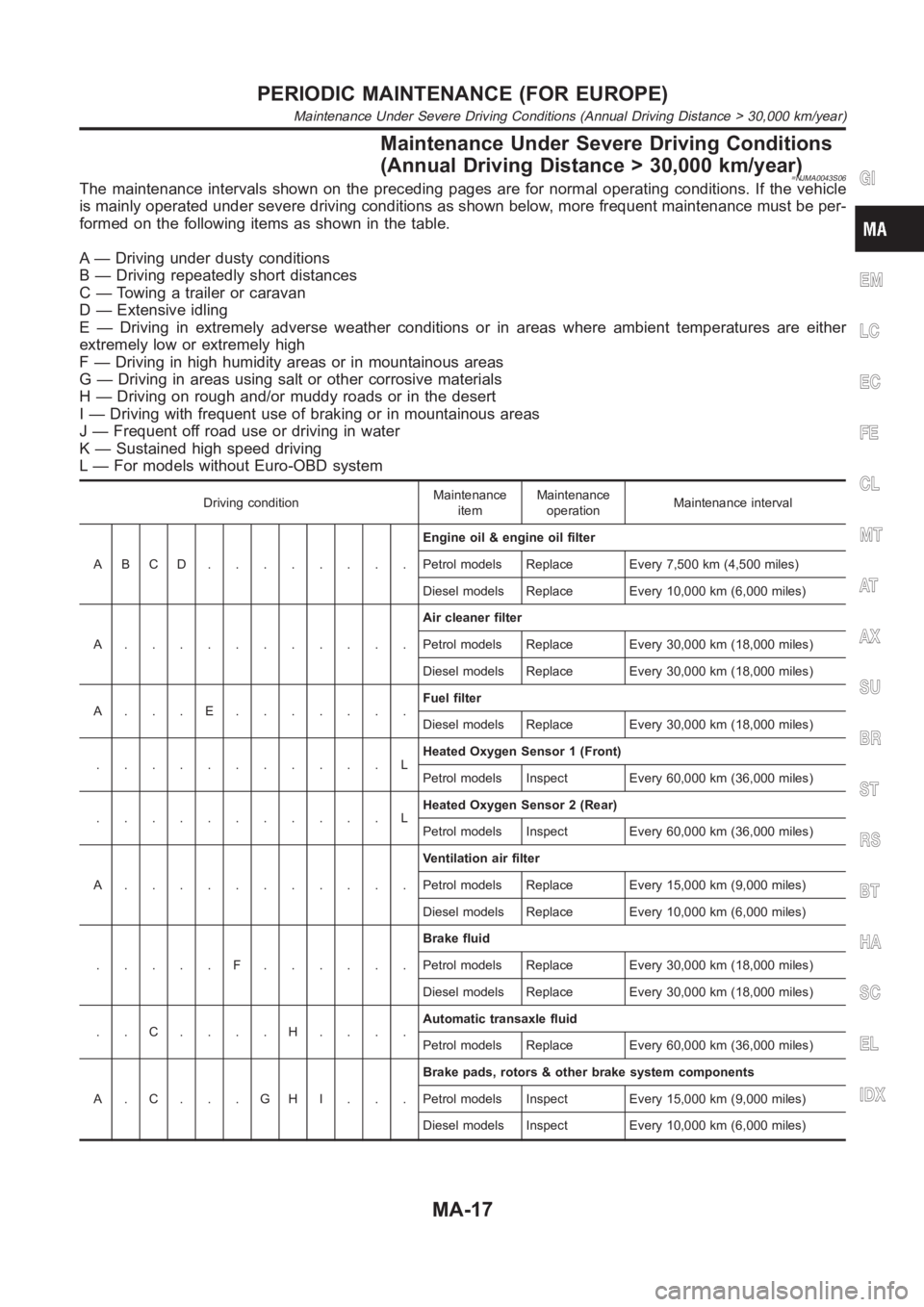
Maintenance Under Severe Driving Conditions
(Annual Driving Distance > 30,000 km/year)
=NJMA0043S06The maintenance intervals shown on the preceding pages are for normal operating conditions. If the vehicle
is mainly operated under severe driving conditions as shown below, more frequent maintenance must be per-
formed on the following items as shown in the table.
A — Driving under dusty conditions
B — Driving repeatedly short distances
C — Towing a trailer or caravan
D — Extensive idling
E — Driving in extremely adverse weather conditions or in areas where ambient temperatures are either
extremely low or extremely high
F — Driving in high humidity areas or in mountainous areas
G — Driving in areas using salt or other corrosive materials
H — Driving on rough and/or muddy roads or in the desert
I — Driving with frequent use of braking or in mountainous areas
J — Frequent off road use or driving in water
K — Sustained high speed driving
L — For models without Euro-OBD system
Driving conditionMaintenance
itemMaintenance
operationMaintenance interval
ABCD........Engine oil & engine oil filter
Petrol models Replace Every 7,500 km (4,500 miles)
Diesel models Replace Every 10,000 km (6,000 miles)
A...........Air cleaner filter
Petrol models Replace Every 30,000 km (18,000 miles)
Diesel models Replace Every 30,000 km (18,000 miles)
A...E.......Fuel filter
Diesel models Replace Every 30,000 km (18,000 miles)
...........LHeated Oxygen Sensor 1 (Front)
Petrol models Inspect Every 60,000 km (36,000 miles)
...........LHeated Oxygen Sensor 2 (Rear)
Petrol models Inspect Every 60,000 km (36,000 miles)
A...........Ventilation air filter
Petrol models Replace Every 15,000 km (9,000 miles)
Diesel models Replace Every 10,000 km (6,000 miles)
.....F......Brake fluid
Petrol models Replace Every 30,000 km (18,000 miles)
Diesel models Replace Every 30,000 km (18,000 miles)
..C....H....Automatic transaxle fluid
Petrol models Replace Every 60,000 km (36,000 miles)
A.C...GHI...Brake pads, rotors & other brake system components
Petrol models Inspect Every 15,000 km (9,000 miles)
Diesel models Inspect Every 10,000 km (6,000 miles)
GI
EM
LC
EC
FE
CL
MT
AT
AX
SU
BR
ST
RS
BT
HA
SC
EL
IDX
PERIODIC MAINTENANCE (FOR EUROPE)
Maintenance Under Severe Driving Conditions (Annual Driving Distance > 30,000 km/year)
MA-17
Page 74 of 3189
Driving conditionMaintenance
itemMaintenance
operationMaintenance interval
......GH....Steering gear & linkage, axle & suspension parts, drive shafts,
exhaust system
Petrol models Inspect Every 30,000 km (18,000 miles)
Diesel models Inspect Every 30,000 km (18,000 miles)
PERIODIC MAINTENANCE (FOR EUROPE)
Maintenance Under Severe Driving Conditions (Annual Driving Distance > 30,000 km/year) (Cont’d)
MA-18
Page 1463 of 3189

PRECAUTIONS
AT-7
D
E
F
G
H
I
J
K
L
MA
B
AT
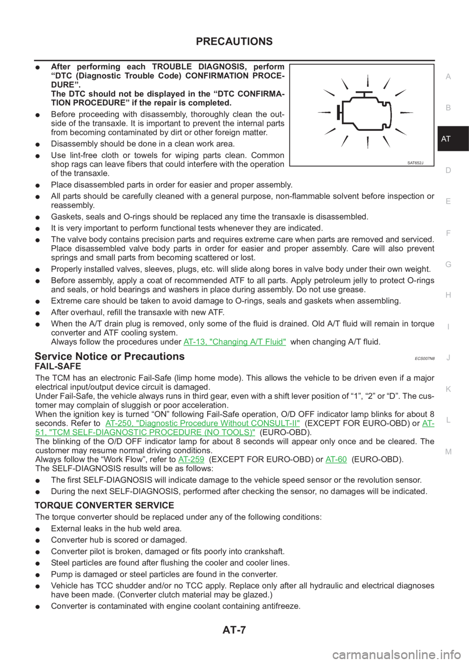
●After performing each TROUBLE DIAGNOSIS, perform
“DTC (Diagnostic Trouble Code) CONFIRMATION PROCE-
DURE”.
The DTC should not be displayed in the “DTC CONFIRMA-
TION PROCEDURE” if the repair is completed.
●Before proceeding with disassembly, thoroughly clean the out-
side of the transaxle. It is important to prevent the internal parts
from becoming contaminated by dirt or other foreign matter.
●Disassembly should be done in a clean work area.
●Use lint-free cloth or towels for wiping parts clean. Common
shop rags can leave fibers that could interfere with the operation
of the transaxle.
●Place disassembled parts in order for easier and proper assembly.
●All parts should be carefully cleaned with a general purpose, non-flammable solvent before inspection or
reassembly.
●Gaskets, seals and O-rings should be replaced any time the transaxle is disassembled.
●It is very important to perform functional tests whenever they are indicated.
●The valve body contains precision parts and requires extreme care when parts are removed and serviced.
Place disassembled valve body parts in order for easier and proper assembly. Care will also prevent
springs and small parts from becoming scattered or lost.
●Properly installed valves, sleeves, plugs, etc. will slide along bores in valve body under their own weight.
●Before assembly, apply a coat of recommended ATF to all parts. Apply petroleum jelly to protect O-rings
and seals, or hold bearings and washers in place during assembly. Do not use grease.
●Extreme care should be taken to avoid damage to O-rings, seals and gaskets when assembling.
●After overhaul, refill the transaxle with new ATF.
●When the A/T drain plug is removed, only some of the fluid is drained. Old A/T fluid will remain in torque
converter and ATF cooling system.
Always follow the procedures under AT-13, "
Changing A/T Fluid" when changing A/T fluid.
Service Notice or PrecautionsECS007N8
FA I L - S A F E
The TCM has an electronic Fail-Safe (limp home mode). This allows the vehicle to be driven even if a major
electrical input/output device circuit is damaged.
Under Fail-Safe, the vehicle always runs in third gear, even with a shift lever position of “1”, “2” or “D”. The cus-
tomer may complain of sluggish or poor acceleration.
When the ignition key is turned “ON” following Fail-Safe operation, O/D OFF indicator lamp blinks for about 8
seconds. Refer to AT- 2 5 0 , "
Diagnostic Procedure Without CONSULT-II" (EXCEPT FOR EURO-OBD) or AT-
51, "TCM SELF-DIAGNOSTIC PROCEDURE (NO TOOLS)" (EURO-OBD).
The blinking of the O/D OFF indicator lamp for about 8 seconds will appear only once and be cleared. The
customer may resume normal driving conditions.
Always follow the “Work Flow”, refer to AT- 2 5 9
(EXCEPT FOR EURO-OBD) or AT- 6 0 (EURO-OBD).
The SELF-DIAGNOSIS results will be as follows:
●The first SELF-DIAGNOSIS will indicate damage to the vehicle speed sensor or the revolution sensor.
●During the next SELF-DIAGNOSIS, performed after checking the sensor, no damages will be indicated.
TORQUE CONVERTER SERVICE
The torque converter should be replaced under any of the following conditions:
●External leaks in the hub weld area.
●Converter hub is scored or damaged.
●Converter pilot is broken, damaged or fits poorly into crankshaft.
●Steel particles are found after flushing the cooler and cooler lines.
●Pump is damaged or steel particles are found in the converter.
●Vehicle has TCC shudder and/or no TCC apply. Replace only after all hydraulic and electrical diagnoses
have been made. (Converter clutch material may be glazed.)
●Converter is contaminated with engine coolant containing antifreeze.
SAT652J
Page 1894 of 3189
AT-438
[ALL]
REPAIR FOR COMPONENT PARTS
3. Install inner and outer gears on oil pump housing.
●Take care with the direction of inner gear.
4. Install oil pump cover on oil pump housing.
a. Wrap masking tape around splines of oil pump cover assembly
to protect seal. Position oil pump cover assembly on oil pump
housing assembly, then remove masking tape.
b. Tighten bolts in a crisscross pattern. Tighten oil pump cover
bolts to the specified torque. Refer to AT- 4 3 5 , "
COMPONENTS"
.
5. Install new seal rings carefully after packing ring groove with
petroleum jelly.
●Do not spread gap of seal ring excessively while install-
ing. The ring may be deformed.
SAT092D
SAT101D
SAT699H
Page 1919 of 3189
REPAIR FOR COMPONENT PARTS
AT-463
[ALL]
D
E
F
G
H
I
J
K
L
MA
B
AT
7. Measure clearance between retaining plate and snap ring. If not
within allowable limit, select proper retaining plate.
8. Check operation of high clutch.
Refer to AT-459, "
High Clutch" .
9. Install seal rings to input shaft.
●Apply petroleum jelly to seal rings.
●Always replace when removed.
●Roll paper around seal rings to prevent seal rings from
spreading.Specified clearance:
Standard 1.4 - 1.8 mm (0.055 - 0.071 in)
Allowable limit 2.4 mm (0.094 in)
Retaining plate:
Refer to AT-515, "
SERVICE DATA AND SPECIFICA-
TIONS (SDS)" .
SAT199D
SAT196D
SAT197D
SAT198D
Page 1932 of 3189
AT-476
[ALL]
REPAIR FOR COMPONENT PARTS
INSPECTION
Rear Internal Gear, Forward Clutch Hub and Overrun Clutch Hub
●Check rubbing surfaces for wear or damage.
Snap Ring, End Bearings and Forward One-way Clutch
●Check snap ring and end bearings for deformation and damage.
●Check forward one-way clutch for wear and damage.
ASSEMBLY
1. Install forward one-way clutch on forward clutch.
●Take care with the direction of forward one-way clutch.
2. Install end bearing on forward one-way clutch.
●Apply petroleum jelly to bearing.
SAT256D
SAT257D
SAT976H
MCIB9019E
Page 1933 of 3189
REPAIR FOR COMPONENT PARTS
AT-477
[ALL]
D
E
F
G
H
I
J
K
L
MA
B
AT
3. Install thrust washer on rear internal gear.
●Apply petroleum jelly to thrust washer.
●Align hooks of thrust washer with holes of rear internal
gear.
4. Install end bearing on rear internal gear.
●Apply petroleum jelly to end bearing.
5. Install forward clutch hub on rear internal gear.
●Check operation of forward one-way clutch.
Hold rear internal gear and turn forward clutch hub.
Check forward clutch hub for correct locking and unlock-
ing directions.
●If not as shown in illustration, check installation direction
of forward one-way clutch.
6. Install thrust washer and overrun clutch hub.
●Apply petroleum jelly to thrust washer.
●Align pawls of thrust washer with holes of overrun clutch
hub.
7. Install overrun clutch hub on rear internal gear.
●Align projections of rear internal gear with holes of over-
run clutch hub.
SAT160F
MCIB9021E
SAT713H
SAT263D
SAT264D
Page 1938 of 3189
AT-482
[ALL]
REPAIR FOR COMPONENT PARTS
5. Press output shaft bearing on output shaft.
6. Press needle bearing on bearing retainer.
7. Install snap ring to bearing retainer.
8. After packing ring grooves with petroleum jelly, carefully install
new seal rings on output shaft and bearing retainer.
●Roll paper around seal rings to prevent seal rings from
spreading.
SAT939D
SAT658D
SAT659D
SAT660D
SAT661D