2003 NISSAN ALMERA N16 ESP
[x] Cancel search: ESPPage 166 of 3189
![NISSAN ALMERA N16 2003 Electronic Repair Manual EM-88
[QG]
CYLINDER BLOCK
●If replacing the piston and piston pin assembly, refer to the “Piston Selection Table” to select the piston
corresponding to the applicable bore](/manual-img/5/57350/w960_57350-165.png "NISSAN ALMERA N16 2003 Electronic Repair Manual EM-88
[QG]
CYLINDER BLOCK
●If replacing the piston and piston pin assembly, refer to the “Piston Selection Table” to select the piston
corresponding to the applicable bore")
EM-88
[QG]
CYLINDER BLOCK
●If replacing the piston and piston pin assembly, refer to the “Piston Selection Table” to select the piston
corresponding to the applicable bore grade of the cylinder block to be used. Refer to EM-80, "
HOW TO
SELECT PISTON" .
Factory installed parts grading:
●Service parts apply only to grade 0.
Unit: mm (in)
CYLINDER BLOCK DISTORTION
●Using a scraper, remove gasket on the cylinder block surface,
and also remove oil, scale, carbon, or other contamination.
CAUTION:
Be careful not to allow gasket flakes to enter the oil or cool-
ant passages.
●Measure the distortion on the block upper face at some different
points in 6 directions.
●If out of the distortion limit, replace the cylinder block.
INNER DIAMETER OF MAIN BEARING HOUSING
●Install the main bearing caps with the main bearings removed,
and tighten the mounting bolts to the specified torque.
●Using a bore gauge, measure the inner diameter of the main
bearing housing.
●If out of the standard, replace the cylinder block and lower cylin-
der block assembly.
NOTE:
These components cannot be replaced as a single unit because
they were processed together.
PISTON TO CYLINDER BORE CLEARANCE
Inner Diameter of Cylinder Bore
●Using a bore gauge, measure cylinder bore for wear, out-of-
round and taper at 6 different points on each cylinder. (X and Y
directions at A, B and C) (Y is in longitudinal direction of engine)
Grade 0 1
Connecting rod small end inner diam-
eter19.000 - 19.006
(0.7480 - 0.7483)19.006 - 19.012
(0.7483 - 0.7485)
Piston pin outer diameter18.989 - 18.995
(0.7476 - 0.7478)18.995 - 19.001
(0.7478 - 0.7481)
Piston pin hole diameterQG15DE18.987 - 18.993
(0.7475 - 0.7478)18.993 - 18.999
(0.7478 - 0.7480)
QG18DE18.993 - 18.996
(0.7478- 0.7479)18.996 - 18.999
(0.7479 - 0.7480)
PBIC0591E
Limit : 0.1 mm (0.004 in)
PBIC0121E
Standard : 53.644 - 53.668 mm (2.1120 - 2.1129 in) dia.
PBIC0611E
PBIC0612E
Page 247 of 3189
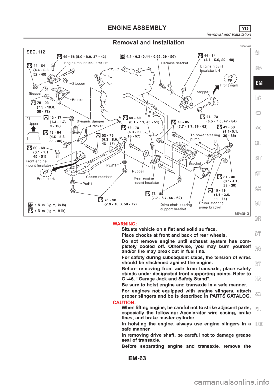
Removal and InstallationNJEM0069
SEM554G
WARNING:
Situate vehicle on a flat and solid surface.
Place chocks at front and back of rear wheels.
Do not remove engine until exhaust system has com-
pletely cooled off. Otherwise, you may burn yourself
and/or fire may break out in fuel line.
For safety during subsequent steps, the tension of wires
should be slackened against the engine.
Before removing front axle from transaxle, place safety
stands under designated front supporting points. Refer to
GI-46, “Garage Jack and Safety Stand”.
Be sure to hoist engine and transaxle in a safe manner.
For engines not equipped with engine slingers, attach
proper slingers and bolts described in PARTS CATALOG.
CAUTION:
When lifting engine, be careful not to strike adjacent parts,
especially the following: Accelerator wire casing, brake
lines, and brake master cylinder.
In hoisting the engine, always use engine slingers in a
safe manner.
In removing drive shaft, be careful not to damage grease
seal of transaxle.
Before separating engine and transaxle, remove the
GI
MA
LC
EC
FE
CL
MT
AT
AX
SU
BR
ST
RS
BT
HA
SC
EL
IDX
ENGINE ASSEMBLYYD
Removal and Installation
EM-63
Page 251 of 3189
Removal and InstallationNJEM0071CAUTION:
When installing bearings, pistons, or other sliding parts,
lubricate contacting surfaces with new engine oil.
Place removed parts such as bearings and bearing caps
in their proper order and direction.
When installing connecting rod nuts, and main bearing
cap bolts, apply new engine oil to threads and seating
surfaces.
Do not allow any magnetic materials to contact the signal
plate of flywheel.
Do not remove the signal plate at back.
Do not place the signal plate side facing under.
Handle with care so as not to damage the signal plate
[especially four places on protrusions for signal of crank
position sensor (TDC sensor)].
DisassemblyNJEM0072PISTON AND CRANKSHAFTNJEM0072S011. Remove engine. Refer to “ENGINE ASSEMBLY”, “Removal
and Installation”, EM-63.
2. Place engine on a work stand.
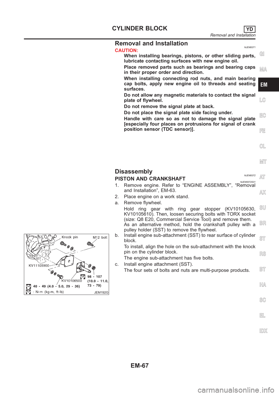
a. Remove flywheel.
Hold ring gear with ring gear stopper (KV10105630,
KV10105610). Then, loosen securing bolts with TORX socket
(size: Q8 E20, Commercial Service Tool) and remove them.
As an alternative method, hold the crankshaft pulley with a
pulley holder (SST) to remove the flywheel.
JEM192G
b. Install engine sub-attachment (SST) to rear surface of cylinder
block.
To install, align the hole on the sub-attachment with the knock
pin on the cylinder block.
The engine sub-attachment has five bolts.
c. Install engine attachment (SST).
The four sets of bolts and nuts are multi-purpose products.
GI
MA
LC
EC
FE
CL
MT
AT
AX
SU
BR
ST
RS
BT
HA
SC
EL
IDX
CYLINDER BLOCKYD
Removal and Installation
EM-67
Page 264 of 3189
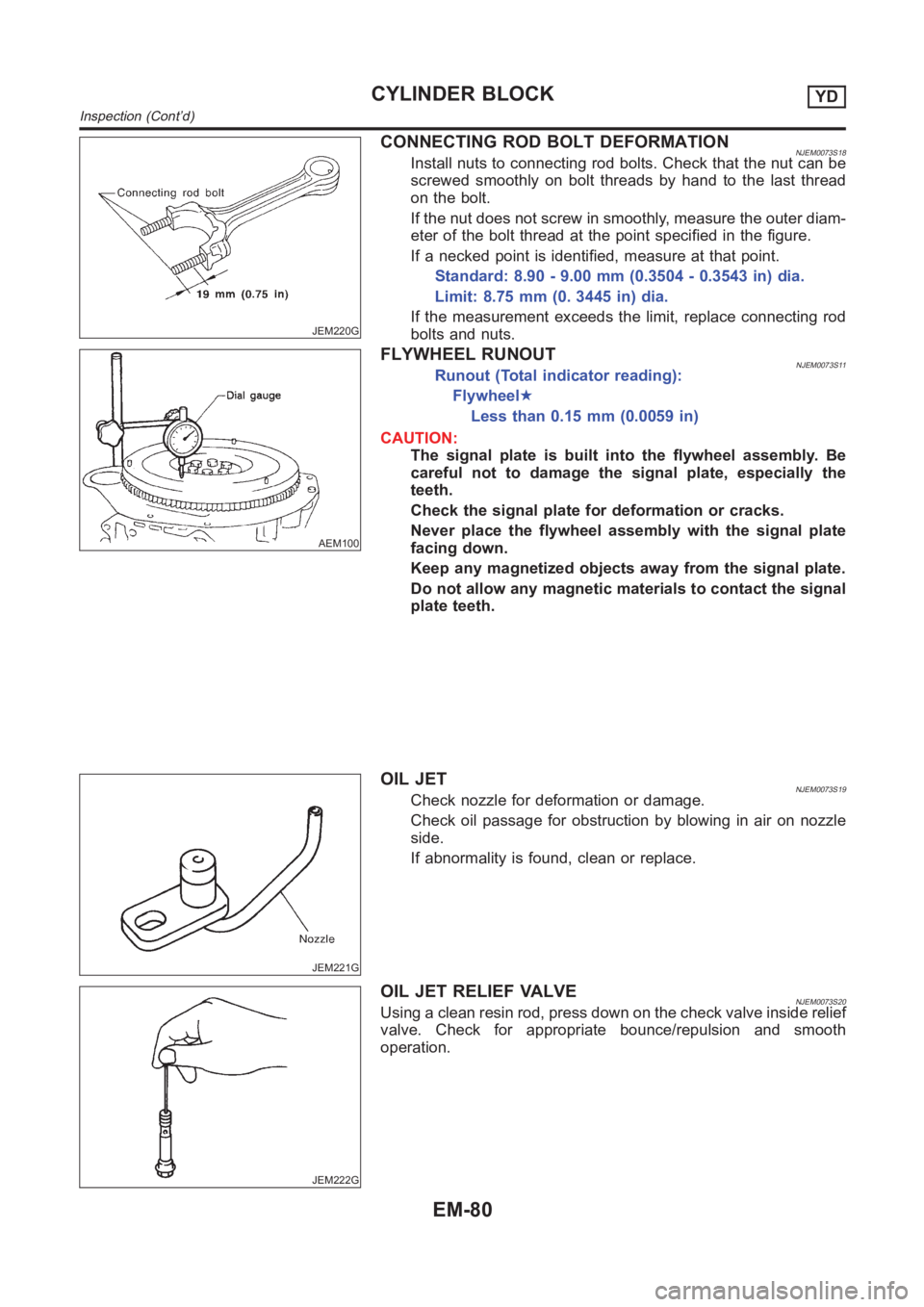
JEM220G
CONNECTING ROD BOLT DEFORMATIONNJEM0073S18Install nuts to connecting rod bolts. Check that the nut can be
screwed smoothly on bolt threads by hand to the last thread
on the bolt.
If the nut does not screw in smoothly, measure the outer diam-
eter of the bolt thread at the point specified in the figure.
If a necked point is identified, measure at that point.
Standard: 8.90 - 9.00 mm (0.3504 - 0.3543 in) dia.
Limit: 8.75 mm (0. 3445 in) dia.
If the measurement exceeds the limit, replace connecting rod
bolts and nuts.
AEM100
FLYWHEEL RUNOUTNJEM0073S11Runout (Total indicator reading):
Flywheel★
Less than 0.15 mm (0.0059 in)
CAUTION:
The signal plate is built into the flywheel assembly. Be
careful not to damage the signal plate, especially the
teeth.
Check the signal plate for deformation or cracks.
Never place the flywheel assembly with the signal plate
facing down.
Keep any magnetized objects away from the signal plate.
Do not allow any magnetic materials to contact the signal
plate teeth.
JEM221G
OIL JETNJEM0073S19Check nozzle for deformation or damage.
Check oil passage for obstruction by blowing in air on nozzle
side.
If abnormality is found, clean or replace.
JEM222G
OIL JET RELIEF VALVENJEM0073S20Using a clean resin rod, press down on the check valve inside relief
valve. Check for appropriate bounce/repulsion and smooth
operation.
CYLINDER BLOCKYD
Inspection (Cont’d)
EM-80
Page 345 of 3189
![NISSAN ALMERA N16 2003 Electronic Repair Manual PRECAUTIONS
EC-15
[QG (WITH EURO-OBD)]
C
D
E
F
G
H
I
J
K
L
MA
EC
PRECAUTIONSPFP:00001
Precautions for Supplemental Restraint System (SRS) “AIR BAG” and “SEAT
BELT PRE-TENSIONER”
EBS00K2V
The](/manual-img/5/57350/w960_57350-344.png "NISSAN ALMERA N16 2003 Electronic Repair Manual PRECAUTIONS
EC-15
[QG (WITH EURO-OBD)]
C
D
E
F
G
H
I
J
K
L
MA
EC
PRECAUTIONSPFP:00001
Precautions for Supplemental Restraint System (SRS) “AIR BAG” and “SEAT
BELT PRE-TENSIONER”
EBS00K2V
The")
PRECAUTIONS
EC-15
[QG (WITH EURO-OBD)]
C
D
E
F
G
H
I
J
K
L
MA
EC
PRECAUTIONSPFP:00001
Precautions for Supplemental Restraint System (SRS) “AIR BAG” and “SEAT
BELT PRE-TENSIONER”
EBS00K2V
The Supplemental Restraint System such as “AIR BAG” and “SEAT BELT PRE-TENSIONER”, used along
with a front seat belt, helps to reduce the risk or severity of injury to the driver and front passenger for certain
types of collision. Information necessary to service the system safely is included in the SRS and SB section of
this Service Manual.
WARNING:
●To avoid rendering the SRS inoperative, which could increase the risk of personal injury or death
in the event of a collision which would result in air bag inflation, all maintenance must be per-
formed by an authorized NISSAN/INFINITI dealer.
●Improper maintenance, including incorrect removal and installation of the SRS, can lead to per-
sonal injury caused by unintentional activation of the system. For removal of Spiral Cable and Air
Bag Module, see the SRS section.
●Do not use electrical test equipment on any circuit related to the SRS unless instructed to in this
Service Manual. SRS wiring harnesses can be identified by yellow and/or orange harness connec-
tors.
On Board Diagnostic (OBD) System of Engine and A/TEBS00K2W
The ECM has an on board diagnostic system. It will light up the malfunction indicator (MI) to warn the driver of
a malfunction causing emission deterioration.
CAUTION:
●Be sure to turn the ignition switch OFF and disconnect the battery ground cable before any repair
or inspection work. The open/short circuit of related switches, sensors, solenoid valves, etc. will
cause the MI to light up.
●Be sure to connect and lock the connectors securely after work. A loose (unlocked) connector will
cause the MI to light up due to the open circuit. (Be sure the connector is free from water, grease,
dirt, bent terminals, etc.)
●Certain systems and components, especially those related to OBD, may use a new style slide-
locking type harness connector. For description and how to disconnect, refer to EL-7.
●Be sure to route and secure the harnesses properly after work. The interference of the harness
with a bracket, etc. may cause the MI to light up due to the short circuit.
●Be sure to connect rubber tubes properly after work. A misconnected or disconnected rubber tube
may cause the MI to light up due to the malfunction of the fuel injection system, etc.
●Be sure to erase the unnecessary malfunction information (repairs completed) from the ECM and
TCM (Transmission control module) before returning the vehicle to the customer.
PrecautionEBS00K2X
●Always use a 12 volt battery as power source.
●Do not attempt to disconnect battery cables while engine is
running.
●Before connecting or disconnecting the ECM harness con-
nector, turn ignition switch OFF and disconnect battery
ground cable. Failure to do so may damage the ECM
because battery voltage is applied to ECM even if ignition
switch is turned off.
●Before removing parts, turn ignition switch OFF and then
disconnect battery ground cable.
SEF289H
Page 372 of 3189
![NISSAN ALMERA N16 2003 Electronic Repair Manual EC-42
[QG (WITH EURO-OBD)]
ON BOARD DIAGNOSTIC (OBD) SYSTEM
SRT Item
The table below shows required self-diagnostic items to set the SRT to “CMPLT”.
*1: If completion of several SRTs is required,](/manual-img/5/57350/w960_57350-371.png "NISSAN ALMERA N16 2003 Electronic Repair Manual EC-42
[QG (WITH EURO-OBD)]
ON BOARD DIAGNOSTIC (OBD) SYSTEM
SRT Item
The table below shows required self-diagnostic items to set the SRT to “CMPLT”.
*1: If completion of several SRTs is required,")
EC-42
[QG (WITH EURO-OBD)]
ON BOARD DIAGNOSTIC (OBD) SYSTEM
SRT Item
The table below shows required self-diagnostic items to set the SRT to “CMPLT”.
*1: If completion of several SRTs is required, perform driving patterns (DTC confirmation procedure), one by one based on the priority for
models with CONSULT-II.
SRT Set Timing
SRT is set as “CMPLT” after self-diagnosis has been performed one or more times. Completion of SRT is
done regardless of whether the result is OK or NG. The set timing is different between OK and NG results and
is shown in the table below.
OK: Self-diagnosis is carried out and the result is OK.
NG: Self-diagnosis is carried out and the result is NG.
—: Self-diagnosis is not carried out.
When all SRT related self-diagnoses showed OK results in a single cycle (Ignition OFF-ON-OFF), the SRT will
indicate “CMPLT”. → Case 1 above
When all SRT related self-diagnoses showed OK results through several different cycles, the SRT will indicate
“CMPLT” at the time the respective self-diagnoses have at least one OK result. → Case 2 above
SRT item
(CONSULT-II indi-
cation)Performance
Priority
*1Required self-diagnostic items to set the SRT to “CMPLT”
Corresponding DTC
No.
CATALYST 2 Three way catalyst function P0420
HO2S 1 Heated oxygen sensor 1 P0132
Heated oxygen sensor 1 P0133
Heated oxygen sensor 1 P0134
Heated oxygen sensor 1 P1143
Heated oxygen sensor 1 P1144
Heated oxygen sensor 2 P0138
Heated oxygen sensor 2 P0139
Heated oxygen sensor 2 P1146
Heated oxygen sensor 2 P1147
HO2S HTR 1 Heated oxygen sensor 1 heater P0031, P0032
Heated oxygen sensor 2 heater P0037, P0038
Self-diagnosis resultExample
DiagnosisIgnition cycle
← ON → OFF ← ON → OFF ← ON → OFF ← ON →
All OK Case 1 P0400 OK (1) — (1) OK (2) — (2)
P0402 OK (1) — (1) — (1) OK (2)
P1402 OK (1) OK (2) — (2) — (2)
SRT of EGR “CMPLT” “CMPLT” “CMPLT” “CMPLT”
Case 2 P0400 OK (1) — (1) — (1) — (1)
P0402 — (0) — (0) OK (1) — (1)
P1402 OK (1) OK (2) — (2) — (2)
SRT of EGR “INCMP” “INCMP” “CMPLT” “CMPLT”
NG exists Case 3 P0400 OK OK — —
P0402 — — — —
P1402 NG — NGNG
(Consecutive
NG)
(1st trip)
DTC1st trip DTC — 1st trip DTCDTC
(= MI “ON”)
SRT of EGR “INCMP” “INCMP” “INCMP” “CMPLT”
Page 373 of 3189
![NISSAN ALMERA N16 2003 Electronic Repair Manual ON BOARD DIAGNOSTIC (OBD) SYSTEM
EC-43
[QG (WITH EURO-OBD)]
C
D
E
F
G
H
I
J
K
L
MA
EC
If one or more SRT related self-diagnoses showed NG results in 2 consecutive cycles, the SRT will also indi-
cate](/manual-img/5/57350/w960_57350-372.png "NISSAN ALMERA N16 2003 Electronic Repair Manual ON BOARD DIAGNOSTIC (OBD) SYSTEM
EC-43
[QG (WITH EURO-OBD)]
C
D
E
F
G
H
I
J
K
L
MA
EC
If one or more SRT related self-diagnoses showed NG results in 2 consecutive cycles, the SRT will also indi-
cate")
ON BOARD DIAGNOSTIC (OBD) SYSTEM
EC-43
[QG (WITH EURO-OBD)]
C
D
E
F
G
H
I
J
K
L
MA
EC
If one or more SRT related self-diagnoses showed NG results in 2 consecutive cycles, the SRT will also indi-
cate “CMPLT”. → Case 3 above
The table above shows that the minimum number of cycles for setting SRT as “INCMP” is one (1) for each
self-diagnosis (Case 1 & 2) or two (2) for one of self-diagnoses (Case 3). However, in preparation for the state
emissions inspection, it is unnecessary for each self-diagnosis to be executed twice (Case 3) for the following
reasons:
●The SRT will indicate “CMPLT” at the time the respective self-diagnoses have one (1) OK result.
●The emissions inspection requires “CMPLT” of the SRT only with OK self-diagnosis results.
●When, during SRT driving pattern, 1st trip DTC (NG) is detected prior to “CMPLT” of SRT, the self-diagno-
sis memory must be erased from ECM after repair.
●If the 1st trip DTC is erased, all the SRT will indicate “INCMP”.
NOTE:
SRT can be set as “CMPLT” together with the DTC(s). Therefore, DTC check must always be carried out
prior to the state emission inspection even though the SRT indicates “CMPLT”.
SRT Service Procedure
If a vehicle has failed the state emissions inspection due to one or more SRT items indicating “INCMP”, review
the flowchart diagnostic sequence on the next page.
Page 375 of 3189
![NISSAN ALMERA N16 2003 Electronic Repair Manual ON BOARD DIAGNOSTIC (OBD) SYSTEM
EC-45
[QG (WITH EURO-OBD)]
C
D
E
F
G
H
I
J
K
L
MA
EC
How to Set SRT Code
To set all SRT codes, self-diagnosis for the items indicated above must be performed one or mo](/manual-img/5/57350/w960_57350-374.png "NISSAN ALMERA N16 2003 Electronic Repair Manual ON BOARD DIAGNOSTIC (OBD) SYSTEM
EC-45
[QG (WITH EURO-OBD)]
C
D
E
F
G
H
I
J
K
L
MA
EC
How to Set SRT Code
To set all SRT codes, self-diagnosis for the items indicated above must be performed one or mo")
ON BOARD DIAGNOSTIC (OBD) SYSTEM
EC-45
[QG (WITH EURO-OBD)]
C
D
E
F
G
H
I
J
K
L
MA
EC
How to Set SRT Code
To set all SRT codes, self-diagnosis for the items indicated above must be performed one or more times. Each
diagnosis may require a long period of actual driving under various conditions.
WITH CONSULT-II
Perform corresponding DTC Confirmation Procedure one by one based on “Performance Priority” in the table
on EC-42, "
SRT Item" .
WITHOUT CONSULT-II
The most efficient driving pattern in which SRT codes can be properly set is explained on the next page. The
driving pattern should be performed one or more times to set all SRT codes.