2003 NISSAN 350Z warning light
[x] Cancel search: warning lightPage 76 of 227
WARNING
IDo not use the HomeLink
Universal
Transceiver with any garage door
opener that lacks safety stop and
reverse features as required by fed-
eral safety standards. (These stan-
dards became effective for opener
models manufactured after April 1,
1982). A garage door opener which
cannot detect an object in the path of
a closing garage door and then auto-
matically stop and reverse, does not
meet current federal safety stan-
dards. Using a garage door opener
without these features increases the
risk of serious injury or death.
IDuring programming, your garage
door or gate may open or close.
Make sure that people and objects
are clear of the garage door or gate
that you are programming.
IYour vehicle's engine should be
turned off while programming the
HomeLink
Universal Transceiver.
PROGRAMMING HomeLinkTo program your HomeLink Transceiver to oper-
ate a garage door, gate, or entry door opener,
home or office lighting, you need to be at the
same location as the device. Note: Garage door
openers (manufactured after 1996) have ªrolling
code protectionº. To program a garage door
opener equipped with ªrolling code protectionº;
you will need to use a ladder to get up to the
garage door opener motor to be able to access
the ªsmart or learnº program button.
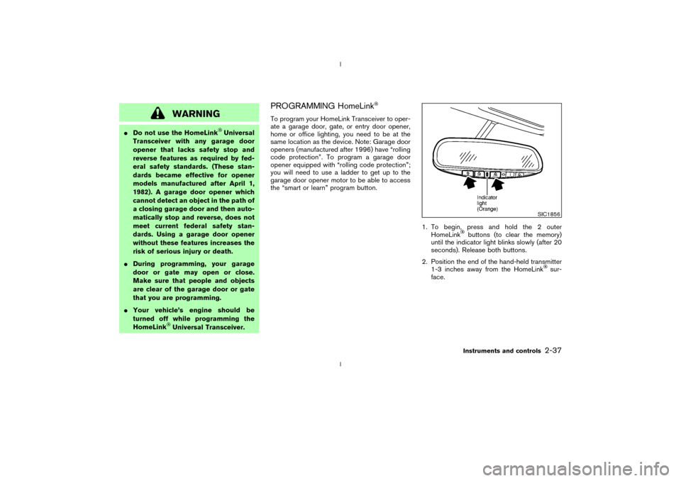
1. To begin, press and hold the 2 outer
HomeLink
buttons (to clear the memory)
until the indicator light blinks slowly (after 20
seconds). Release both buttons.
2. Position the end of the hand-held transmitter
1-3 inches away from the HomeLink
sur-
face.
SIC1856
Instruments and controls
2-37
Z
02.9.13/Z33-D/V5.0
X
Page 88 of 227

LOCK button again for 3 more seconds.Releasing the rear hatch1. Push the REAR HATCH button on the keyfob
for longer than 0.5 seconds with the key
removed from the ignition key cylinder.
2. The rear hatch opens.Using the panic alarmIf you are near your vehicle and feel threatened,
you may activate the alarm to call attention as
follows:
1. Push the PANIC button on the keyfob for
longer than 0.5 secondswith the key
removed from the ignition key cylinder.
2. The theft warning alarm and headlights will
stay on for 30 seconds.
3. The panic alarm stops when:
IIt has run for 30 seconds, or
IThe LOCK or the UNLOCK button is
pressed, or
IThe PANIC or the REAR HATCH button is
pushed on the keyfob for longer than 0.5
seconds.
BATTERY REPLACEMENTReplace the battery as follows:
1. Open the lid using a suitable tool.
2. Replace the battery with a new one.Recommended battery: CR2025 or equiva-
lent
Make sure that theÅside faces the
bottom case.
3. Close the lid securely.
4. Push the keyfob button two or three times to
check its operation.
See your NISSAN dealer if you need any assis-
tance for replacement.
If the battery is removed for any reason
other than replacement, perform step 4
above.
IBe careful not to touch the circuit board
and the battery terminal.
IAn improperly disposed battery can
harm the environment. Always confirm
local regulations for battery disposal.
IThe keyfob is water-resistant; however,
if it gets wet, immediately wipe it com-
pletely dry.
IWhen changing batteries, do not let
dust or oil get on the keyfob.
FCC Notice:
Changes or modifications not expressly
approved by the manufacturer compliance
SPA1374
Pre-driving checks and adjustments
3-7
Z
02.9.13/Z33-D/V5.0
X
Page 89 of 227
could void the user's authority to operate
the equipment. This device complies with
Part 15 of the FCC Rules and RSS-210 of
Industry Canada. Operation is subject to
the following two conditions: (1) This de-
vice may not cause harmful interference,
and (2) this device must accept any inter-
ference received, including interference
that may cause undesired operation of the
device.
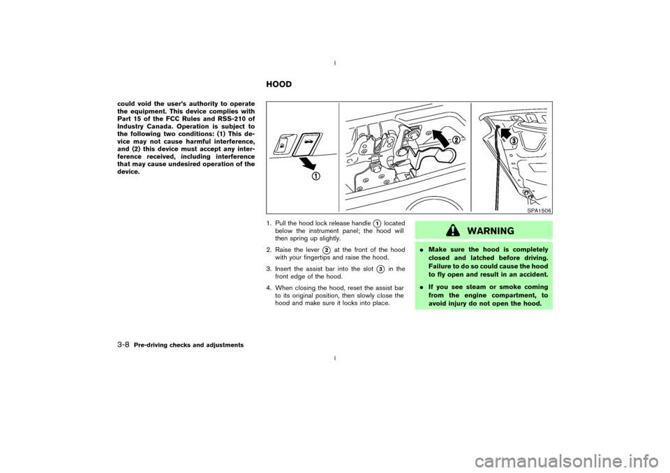
1. Pull the hood lock release handle
q1
located
below the instrument panel; the hood will
then spring up slightly.
2. Raise the lever
q2
at the front of the hood
with your fingertips and raise the hood.
3. Insert the assist bar into the slot
q3
in the
front edge of the hood.
4. When closing the hood, reset the assist bar
to its original position, then slowly close the
hood and make sure it locks into place.
WARNING
IMake sure the hood is completely
closed and latched before driving.
Failure to do so could cause the hood
to fly open and result in an accident.
IIf you see steam or smoke coming
from the engine compartment, to
avoid injury do not open the hood.
SPA1506
HOOD
3-8
Pre-driving checks and adjustments
Z
02.9.13/Z33-D/V5.0
X
Page 90 of 227
WARNING
Do not drive with the rear hatch open.
This could allow dangerous exhaust
gases to be drawn into the vehicle. See
ªPrecautions when starting and drivingº
in the ª5. Starting and drivingº section
for exhaust gas.
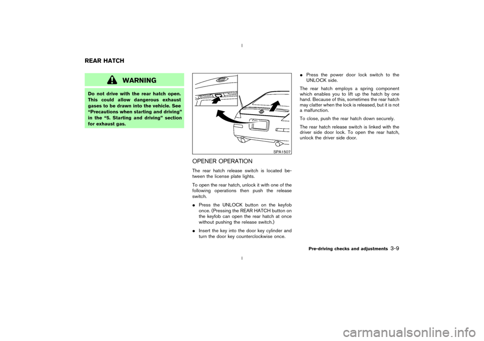
OPENER OPERATIONThe rear hatch release switch is located be-
tween the license plate lights.
To open the rear hatch, unlock it with one of the
following operations then push the release
switch.
IPress the UNLOCK button on the keyfob
once. (Pressing the REAR HATCH button on
the keyfob can open the rear hatch at once
without pushing the release switch.)
IInsert the key into the door key cylinder and
turn the door key counterclockwise once.IPress the power door lock switch to the
UNLOCK side.
The rear hatch employs a spring component
which enables you to lift up the hatch by one
hand. Because of this, sometimes the rear hatch
may clatter when the lock is released, but it is not
a malfunction.
To close, push the rear hatch down securely.
The rear hatch release switch is linked with the
driver side door lock. To open the rear hatch,
unlock the driver side door.
SPA1507
REAR HATCH
Pre-driving checks and adjustments
3-9
Z
02.9.13/Z33-D/V5.0
X
Page 94 of 227
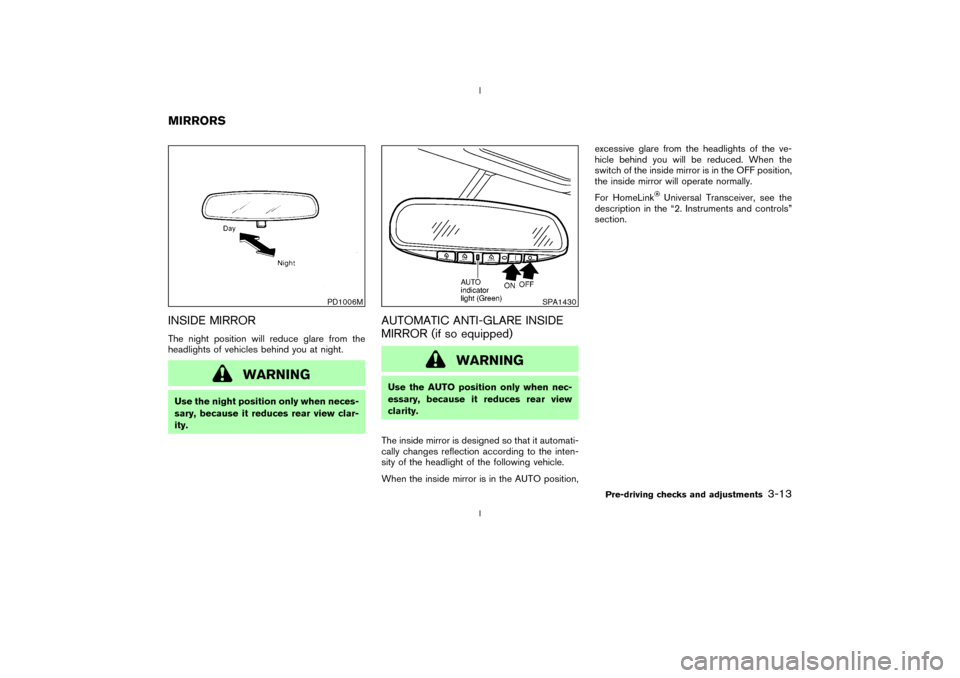
INSIDE MIRRORThe night position will reduce glare from the
headlights of vehicles behind you at night.
WARNING
Use the night position only when neces-
sary, because it reduces rear view clar-
ity.
AUTOMATIC ANTI-GLARE INSIDE
MIRROR (if so equipped)
WARNING
Use the AUTO position only when nec-
essary, because it reduces rear view
clarity.
The inside mirror is designed so that it automati-
cally changes reflection according to the inten-
sity of the headlight of the following vehicle.
When the inside mirror is in the AUTO position,excessive glare from the headlights of the ve-
hicle behind you will be reduced. When the
switch of the inside mirror is in the OFF position,
the inside mirror will operate normally.
For HomeLink
Universal Transceiver, see the
description in the ª2. Instruments and controlsº
section.
PD1006M
SPA1430
MIRRORS
Pre-driving checks and adjustments
3-13
Z
02.9.13/Z33-D/V5.0
X
Page 120 of 227
d. You have had an accident involv-
ing damage to the exhaust system,
underbody, or rear of the vehicle.
THREE WAY CATALYSTThe three way catalyst is an emission control
device installed in the exhaust system. Exhaust
gases in the converter are burned at high tem-
peratures to help reduce pollutants.
WARNING
IThe exhaust gas and the exhaust sys-
tem are very hot. Keep people, ani-
mals or flammable materials away
from the exhaust system compo-
nents.
IDo not stop or park the vehicle over
flammable materials such as dry
grass, waste paper or rags. They may
ignite and cause a fire.
CAUTION
IDo not use leaded gasoline. Deposits
from leaded gasoline seriously re-
duce the three way catalyst's ability
to help reduce exhaust pollutants.
IKeep your engine tuned up. Malfunc-
tions in the ignition, fuel injection, or
electrical systems can cause overrich
fuel flow into the three way catalyst,
causing it to overheat. Do not keep
driving if the engine misfires, or if
noticeable loss of performance or
other unusual operating conditions
are detected. Have the vehicle in-
spected promptly by a NISSAN
dealer.
IAvoid driving with an extremely low
fuel level. Running out of fuel could
cause the engine to misfire, damag-
ing the three way catalyst.
IDo not race the engine while warm-
ing it up.
IDo not push or tow your vehicle to
start the engine.
LOW TIRE PRESSURE WARNING
SYSTEM (if so equipped)The low tire pressure warning system displays
pressure of all tires (except the spare tire) on the
trip computer by sending a signal from a sensor
that is installed in each wheel.
The low tire pressure warning system will acti-
vate only when the vehicle is driven at speeds
above 20 MPH (32 km/h). Also, this system may
not detect a sudden drop in tire pressure (for
example, a flat tire by catching something while
driving).
Frequently check the tire pressure indicator on
the trip computer and adjust pressure of each
tire properly. See ªTrip computerº in the ª2.
Instruments and controlsº section for the tire
pressure indicator.Flat tire warningIf the vehicle is being driven with a flat tire or
extremely low tire pressure (lower than 28 psi),
the low tire pressure warning light comes on,
and the chime sounds for about 10 seconds. On
the trip computer, the PSI indicator starts flash-
ing and the current display switches to the tire
pressure indicator.
For additional information regarding the above
warning, see ªTrip computerº and
Starting and driving
5-3
Z
02.9.13/Z33-D/V5.0
X
Page 121 of 227
ªWarning/indicator lights and audible remind-
ersº in the ª2. Instruments and controlsº section.
WARNING
IIf the low tire pressure warning light
in the meter panel comes on and/or
the PSI indicator on the trip computer
flashes while driving, avoid sudden
steering maneuvers or abrupt brak-
ing, reduce vehicle speed, pull off the
road to a safe location and stop the
vehicle as soon as possible. Serious
vehicle damage could occur and may
lead to an accident and could result
in serious personal injury. Check the
pressure for all four tires and adjust
the pressure to the COLD tire pres-
sure shown on the tire placard. If you
have a flat tire, replace it with a spare
tire as soon as possible. (See ªFlat
tireº in the ª6. In case of emergencyº
section for changing a flat tire.)
IWhen a spare tire is mounted or a
wheel is replaced, tire pressure will
not be indicated and the low tirepressure warning system will not
function. Contact your NISSAN
dealer as soon as possible for tire
replacement and/or system reset-
ting.
IDo not inject any tire liquid or aerosol
tire sealant into the tires, as this may
cause a malfunction of the tire pres-
sure sensors.
CAUTION
Do not place metalized film or any metal
parts (antenna, etc.) on the windows.
This may cause poor reception of the
signals from the tire pressure sensors,
and the low tire pressure warning sys-
tem will not function properly.
FCC Notice:
Changes or modifications not expressly
approved by the manufacturer compliance
could void the user's authority to operate
the equipment.This device complies with Part 15 of the
FCC Rules and RSS-210 of Industry
Canada.
Operation is subject to the following two
conditions: (1) This device may not cause
harmful interference, and (2) this device
must accept any interference received, in-
cluding interference that may cause undes-
ired operation of the device.
AVOIDING COLLISION AND
ROLLOVER
WARNING
Failure to operate this vehicle in a safe
and prudent manner may result in loss
of control or an accident.
Be alert and drive defensively at all times. Obey
all traffic regulations. Avoid excessive speed,
high speed cornering, or sudden steering ma-
neuvers, because these driving practices could
cause you to lose control of your vehicle.As
with any vehicle, a loss of control could
result in a collision with other vehicles or
objects, or cause the vehicle to rollover,
particularly if the loss of control causes the
vehicle to slide sideways.Be attentive at all
5-4
Starting and driving
Z
02.9.13/Z33-D/V5.0
X
Page 123 of 227
1. Move the selector lever into the P (Park)
position.
2. Turn the ignition key slightly in the ON direc-
tion.
3. Turn the key toward the LOCK position.
4. Remove the key.
If the key is removed from the ignition switch, the
selector lever cannot be moved from P (Park)
position.The selector lever can be moved if
the ignition switch is in the ON position
and the foot brake pedal is depressed.
There is an OFF position in between LOCK and
ACC, although it does not show on the lock
cylinder. When the ignition is in OFF the steering
wheel is not locked.
In order for the steering wheel to be locked, it
must be turned about 1/6 of a turn counterclock-
wise from the straight up position.
To lock the steering wheel, turn the key to
the LOCK position. Remove the key. To
unlock the steering wheel, insert the key
and turn it gently while rotating the steer-
ing wheel slightly right and left.
WARNING
Never remove or turn the key to the
LOCK position while driving. The steer-
ing wheel will lock. This may cause the
driver to lose control of the vehicle and
could result in serious vehicle damage
and/or personal injury.
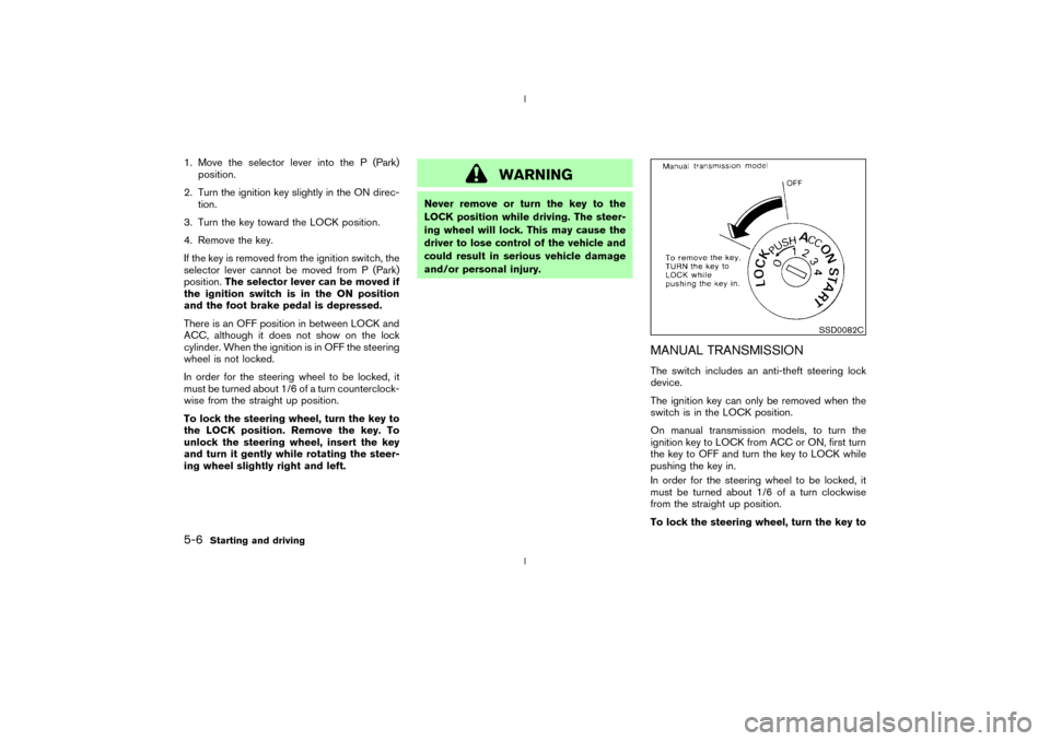
MANUAL TRANSMISSIONThe switch includes an anti-theft steering lock
device.
The ignition key can only be removed when the
switch is in the LOCK position.
On manual transmission models, to turn the
ignition key to LOCK from ACC or ON, first turn
the key to OFF and turn the key to LOCK while
pushing the key in.
In order for the steering wheel to be locked, it
must be turned about 1/6 of a turn clockwise
from the straight up position.
To lock the steering wheel, turn the key to
SSD0082C
5-6
Starting and driving
Z
02.9.13/Z33-D/V5.0
X