Page 256 of 376
256 Practical hintsWhat to do if …Problem
Possible cause
Suggested solution
?
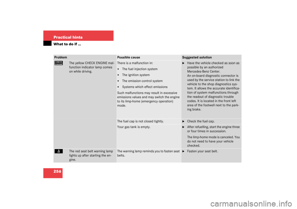
The yellow CHECK ENGINE mal-
function indicator lamp comes
on while driving.
There is a malfunction in:�
The fuel injection system
�
The ignition system
�
The emission control system
�
Systems which effect emissions
Such malfunctions may result in excessive
emissions values and may switch the engine
to its limp-home (emergency operation)
mode.
�
Have the vehicle checked as soon as
possible by an authorized
Mercedes-Benz Center.
An on-board diagnostic connector is
used by the service station to link the
vehicle to the shop diagnostics sys-
tem. It allows the accurate identifica-
tion of system malfunctions through
the readout of diagnostic trouble
codes. It is located in the front left
area of the footwell next to the park-
ing brake.
The fuel cap is not closed tightly.
�
Check the fuel cap.
Your gas tank is empty.
�
After refuelling, start the engine three
or four times in succession.
The limp-home mode is canceled. You
do not need to have your vehicle
checked.
<
The red seat belt warning lamp
lights up after starting the en-
gine.
The warning lamp reminds you to fasten seat
belts.
�
Fasten your seat belt.
Page 275 of 376
275 Practical hints
What to do if …
Left display
Right display
Possible cause
Possible solution
.
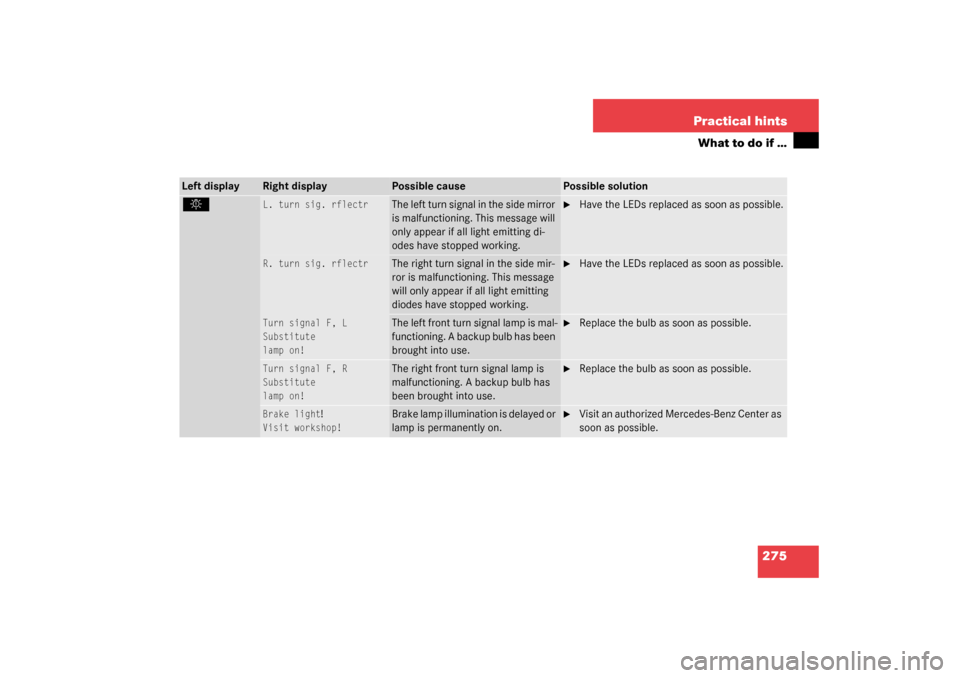
L. turn sig. rflectr
The left turn signal in the side mirror
is malfunctioning. This message will
only appear if all light emitting di-
odes have stopped working.
�
Have the LEDs replaced as soon as possible.
R. turn sig. rflectr
The right turn signal in the side mir-
ror is malfunctioning. This message
will only appear if all light emitting
diodes have stopped working.
�
Have the LEDs replaced as soon as possible.
Turn signal F, L
Substitute
lamp on!
The left front turn signal lamp is mal-
functioning. A backup bulb has been
brought into use.
�
Replace the bulb as soon as possible.
Turn signal F, R
Substitute
lamp on!
The right front turn signal lamp is
malfunctioning. A backup bulb has
been brought into use.
�
Replace the bulb as soon as possible.
Brake light
!
Visit workshop!
Brake lamp illumination is delayed or
lamp is permanently on.
�
Visit an authorized Mercedes-Benz Center as
soon as possible.
Page 276 of 376
276 Practical hintsWhat to do if …Left display
Right display
Possible cause
Possible solution
.
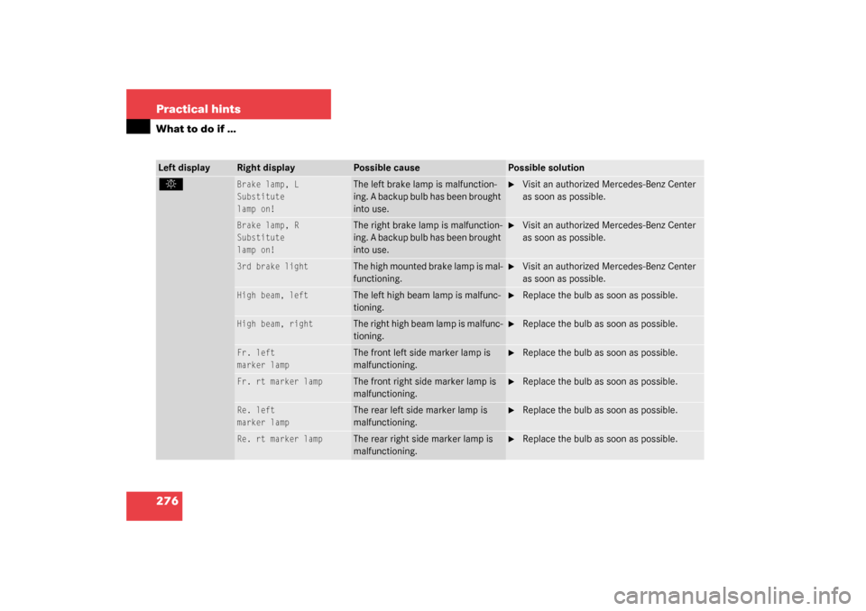
Brake lamp, L
Substitute
lamp on!
The left brake lamp is malfunction-
ing. A backup bulb has been brought
into use.
�
Visit an authorized Mercedes-Benz Center
as soon as possible.
Brake lamp, R
Substitute
lamp on!
The right brake lamp is malfunction-
ing. A backup bulb has been brought
into use.
�
Visit an authorized Mercedes-Benz Center
as soon as possible.
3rd brake light
The high mounted brake lamp is mal-
functioning.
�
Visit an authorized Mercedes-Benz Center
as soon as possible.
High beam, left
The left high beam lamp is malfunc-
tioning.
�
Replace the bulb as soon as possible.
High beam, right
The right high beam lamp is malfunc-
tioning.
�
Replace the bulb as soon as possible.
Fr. left
marker lamp
The front left side marker lamp is
malfunctioning.
�
Replace the bulb as soon as possible.
Fr. rt marker lamp
The front right side marker lamp is
malfunctioning.
�
Replace the bulb as soon as possible.
Re. left
marker lamp
The rear left side marker lamp is
malfunctioning.
�
Replace the bulb as soon as possible.
Re. rt marker lamp
The rear right side marker lamp is
malfunctioning.
�
Replace the bulb as soon as possible.
Page 295 of 376
295 Practical hints
Replacing bulbs
Replacing bulbs
Bulbs
Safe vehicle operation depends on proper
exterior lighting and signaling. It is there-
fore essential that all bulbs and lamp as-
semblies are in good working order at all
times.
Correct headlamp adjustment is extremely
important. Have headlamps checked and
readjusted at regular intervals and when a
bulb has been replaced. See your autho-
rized Mercedes-Benz Center for headlamp
adjustment
iIf the headlamps are fogged up on the
inside as a result of high humidity, driv-
ing the vehicle a distance should clear
up the fogging.
iBackup bulbs will be brought into use
when the following lamps malfunction:�
Turn signal lamps
�
Brake lamps
�
Parking lamps
�
Tail lamps
Page 297 of 376
297 Practical hints
Replacing bulbs
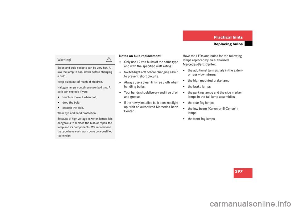
Notes on bulb replacement�
Only use 12 volt bulbs of the same type
and with the specified watt rating.
�
Switch lights off before changing a bulb
to prevent short circuits.
�
Always use a clean lint-free cloth when
handling bulbs.
�
Your hands should be dry and free of oil
and grease.
�
If the newly installed bulb does not light
up, visit an authorized Mercedes-Benz
Center.Have the LEDs and bulbs for the following
lamps replaced by an authorized
Mercedes-Benz Center:
�
the additional turn signals in the exteri-
or rear view mirrors
�
the high mounted brake lamp
�
the brake lamps
�
the parking lamps and the side marker
lamps in the tail lamp assemblies
�
the rear fog lamps
�
the low beam (Xenon or Bi-Xenon*)
lamps
�
the front fog lamps
Warning!
G
Bulbs and bulb sockets can be very hot. Al-
low the lamp to cool down before changing
a bulb.
Keep bulbs out of reach of children.
Halogen lamps contain pressurized gas. A
bulb can explode if you:�
touch or move it when hot,
�
drop the bulb,
�
scratch the bulb.
Wear eye and hand protection.
Because of high voltage in Xenon lamps, it is
dangerous to replace the bulb or repair the
lamp and its components. We recommend
that you have such work done by a qualified
technician.
Page 305 of 376
305 Practical hints
Flat tire
�
Drive the vehicle back and forth very
slowly approximately 30 ft (10 m).
This distributes the TIREFIT sealant ma-
terial inside the tire.
�
Take the electric air pump out of the
trunk.
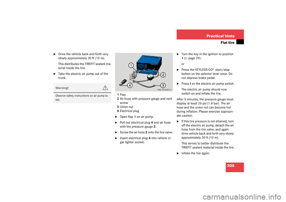
1Flap
2Air hose with pressure gauge and vent
screw
3Union nut
4Electrical plug
�
Open flap 1 on air pump.
�
Pull out electrical plug 4 and air hose
with the pressure gauge 2.
�
Screw the air hose 2 onto the tire valve.
�
Insert electrical plug 4 into vehicle ci-
gar lighter socket.
�
Turn the key in the ignition to position
1 (
�page 29).
or
�
Press the KEYLESS-GO* start/stop
button on the selector lever once. Do
not depress brake pedal.
�
Press I on the electric air pump switch.
The electric air pump should now
switch on and inflate the tire.
After 5 minutes, the pressure gauge must
display at least 26 psi (1.8 bar). The air
hose and the union nut can become hot
during inflation. Please exercise appropri-
ate caution.
�
If this tire pressure is not attained, turn
off the electric air pump, detach the air
hose from the tire valve, and again
drive vehicle back and forth very slowly
approximately 30 ft (10 m).
This serves to better distribute the
TIREFIT sealant material inside the tire.
�
Inflate the tire again.
Warning!
G
Observe safety instructions on air pump la-
bel.
Page 309 of 376
309 Practical hints
Flat tire
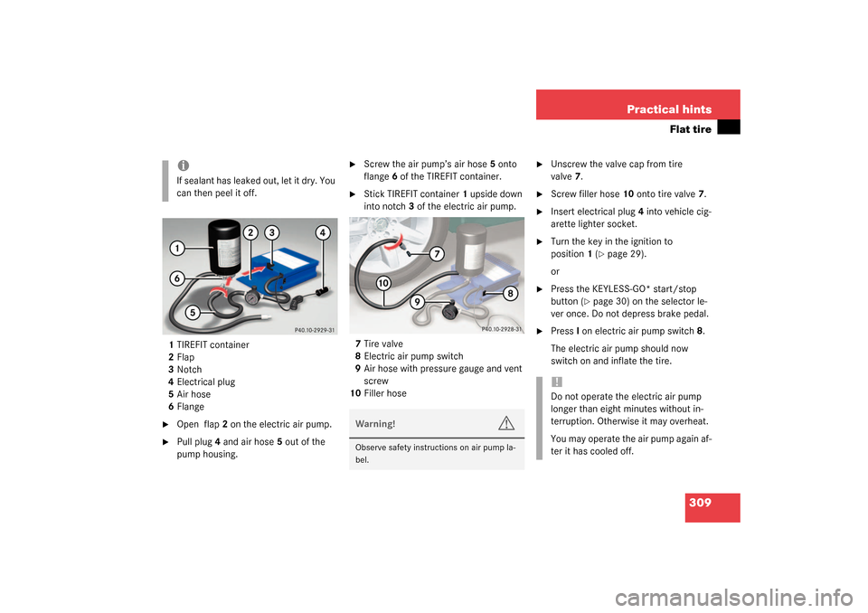
1TIREFIT container
2Flap
3Notch
4Electrical plug
5Air hose
6Flange�
Open flap2 on the electric air pump.
�
Pull plug4 and air hose5 out of the
pump housing.
�
Screw the air pump’s air hose5 onto
flange6 of the TIREFIT container.
�
Stick TIREFIT container1 upside down
into notch3 of the electric air pump.
7Tire valve
8Electric air pump switch
9Air hose with pressure gauge and vent
screw
10Filler hose
�
Unscrew the valve cap from tire
valve7.
�
Screw filler hose10 onto tire valve7.
�
Insert electrical plug4 into vehicle cig-
arette lighter socket.
�
Turn the key in the ignition to
position1 (
�page 29).
or
�
Press the KEYLESS-GO* start/stop
button (
�page 30) on the selector le-
ver once. Do not depress brake pedal.
�
PressI on electric air pump switch8.
The electric air pump should now
switch on and inflate the tire.
iIf sealant has leaked out, let it dry. You
can then peel it off.
Warning!
G
Observe safety instructions on air pump la-
bel.
!Do not operate the electric air pump
longer than eight minutes without in-
terruption. Otherwise it may overheat.
You may operate the air pump again af-
ter it has cooled off.
Page 316 of 376
316 Practical hintsFlat tireInflating the spare tire�
Take the electric air pump out of the
trunk (
�page 289).
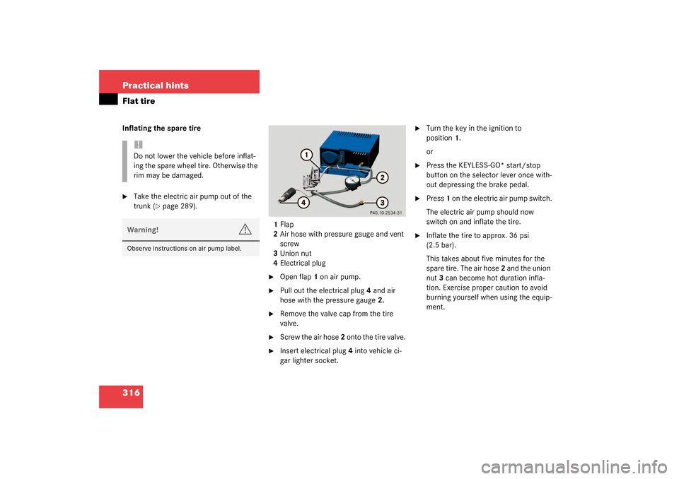
1Flap
2Air hose with pressure gauge and vent
screw
3Union nut
4Electrical plug
�
Open flap 1 on air pump.
�
Pull out the electrical plug 4 and air
hose with the pressure gauge 2.
�
Remove the valve cap from the tire
valve.
�
Screw the air hose 2 onto the tire valve.
�
Insert electrical plug 4 into vehicle ci-
gar lighter socket.
�
Turn the key in the ignition to
position1.
or
�
Press the KEYLESS-GO* start/stop
button on the selector lever once with-
out depressing the brake pedal.
�
Press 1 on the electric air pump switch.
The electric air pump should now
switch on and inflate the tire.
�
Inflate the tire to approx. 36 psi
(2.5 bar).
This takes about five minutes for the
spare tire. The air hose 2 and the union
nut 3 can become hot duration infla-
tion. Exercise proper caution to avoid
burning yourself when using the equip-
ment.
!Do not lower the vehicle before inflat-
ing the spare wheel tire. Otherwise the
rim may be damaged.Warning!
G
Observe instructions on air pump label.