Page 256 of 321
.
The jack take-up brackets are located di-
rectly behi")
256 Practical hintsFlat tire
�
On wheel to be changed, loosen but do
not yet remove the wheel bolts (ap-
proximately one full turn with wrench).
The jack take-up brackets are located di-
rectly behind the front wheel housings and
in front of the rear wheel housings.1Take-up bracket
2Jack
�
Place jack on firm ground.
�
Position jack2 under the take-up
bracket1 so that it is always vertical
(plumb-line) as seen from the side,
even if the vehicle is parked on an in-
cline.
�
Jack up the vehicle until the wheel is a
maximum of 1.2 in (3 cm) from the
ground. Never start engine while vehi-
cle is raised.
Warning!
G
The jack is designed exclusively for jacking
up the vehicle at the jack take-up brackets
built into both sides of the vehicle. To help
avoid personal injury, use the jack only to lift
the vehicle during a wheel change. Never
get beneath the vehicle while it is supported
by the jack. Keep hands and feet away from
the area under the lifted vehicle. Always
firmly set parking brake and block wheels
before raising vehicle with jack.
Do not disengage parking brake while the
vehicle is raised. Be certain that the jack is
always vertical (plumb line) when in use, es-
pecially on hills. Always try to use the jack
on level surface. Make sure that the jack
arm is fully seated in the jack take-up brack-
et. Always lower the vehicle onto sufficient
capacity jackstands before working under
the vehicle.
!Do not position the jack on the body of
the vehicle, as this may cause damage
to the vehicle.
Page 258 of 321

258 Practical hintsFlat tireLowering the vehicle�
Lower vehicle by turning crank coun-
terclockwise until vehicle is resting ful-
ly on its own weight.
�
Remove the jack.1-5 Wheel bolts
�
Tighten the five wheel bolts evenly, fol-
lowing the diagonal sequence illustrat-
ed (1 to 5), until all bolts are tight.
Observe a tightening torque of
110 ft lb (150 Nm).
�
Store jack and tool kit.
Warning!
G
Use only genuine equipment
Mercedes-Benz wheel bolts. They are identi-
fied by the Mercedes star. Other wheel bolts
may come loose.
Do not tighten the wheel bolts when the ve-
hicle is raised. Otherwise the vehicle could
tip over.
Warning!
G
Have the tightening torque checked after
changing a wheel. The wheels could come
loose if they are not tightened to a torque of
110 ft lb (150 Nm).iThe removed road wheel cannot be
stored in the spare wheel carrier or in-
side the storage compartment in the
rear cargo area (ML 55 AMG), but
should be transported in the rear cargo
compartment wrapped in a protective
cover supplied with the vehicle.
The protective cover is located in the
rear cargo compartment behind the
cover in the right side trim panel.
Page 261 of 321

261 Practical hints
Battery
Battery
The battery is located in the engine com-
partment on the right-hand side.
Disconnecting the battery�
Turn off all electrical consumers.
�
Open the hood (
�page 202).
�
Disconnect the battery negative lead.
�
Remove the cover from the positive ter-
minal.
�
Disconnect the battery positive lead.
Warning!
G
Failure to follow these instructions can re-
sult in severe injury or death.
Never lean over batteries while connecting,
you might get injured.
Battery fluid contains sulfuric acid. Do not
allow this fluid to come in contact with eyes,
skin or clothing. In case it does, immediately
flush affected area with water and seek
medical help if necessary.
A battery will also produce hydrogen gas,
which is flammable and explosive. Keep
flames or sparks away from battery, avoid
improper connection of jumper cables,
smoking etc.
!Never loosen or detach battery termi-
nal clamps while the engine is running
or the key is in the steering lock. Other-
wise the alternator and other electronic
components could be severely dam-
aged.
Have the battery checked regularly by
an authorized Mercedes-Benz Light
Truck Center.
Refer to Service Booklet for mainte-
nance intervals or contact your autho-
rized Mercedes-Benz Light Truck
Center for further information.Warning!
G
Do not place metal objects on the battery as
this could result in a short circuit.
Use leak-proof battery only to avoid the risk
of acid burns in the event of an accident.
Warning!
G
With a disconnected battery�
y o u w i l l n o l o n g e r b e a b l e t o t u r n t h e k e y
in the steering lock
�
the selector lever will remain locked in
positionP
Page 262 of 321

262 Practical hintsBatteryRemoving the batteries�
Remove the screw securing the bat-
tery.
�
Remove the battery support and brack-
et. Take out the battery.
Charging and reinstalling batteries�
Charge battery in accordance with the
instructions of the battery charger
manufacturer.
�
Reinstall the charged battery. Follow
the previously described steps in re-
verse order.
Reconnecting the batteries�
Turn off all electrical consumers.
�
Connect the positive lead and fasten its
cover.
�
Connect the negative lead.
Warning!
G
Never charge a battery while still installed in
the vehicle. Gases may escape during charg-
ing and cause explosions that may result in
paint damage, corrosion or personal injury.
!Never invert the terminal connections!!The battery, its filler caps and the vent
tube must always be securely installed
when the vehicle is in operation.
iThe following procedures must be car-
ried out following any interruption of
battery power (e.g. due to reconnec-
tion):�
Set the clock (
�page 112).
�
Set the date in trip computer
(�page 172).
�
Calibrate the compass
(�page 174).
�
Resynchronize the ESP
(�page 225).
�
Resynchronize side windows
(�page 136).
�
Resynchronize sliding/pop-up
roof*(
�page 138).
Page 267 of 321

267 Practical hints
Towing the vehicle
Towing the vehicle
Mercedes-Benz recommends that the vehi-
cle be transported with all wheels off the
ground using flatbed or appropriate wheel
lift/dolly equipment. This method is pref-
erable to other types of towing.When circumstances do not permit the
recommended towing methods, the vehi-
cle may be towed with all wheels on the
ground only so far as necessary to have the
vehicle moved to a safe location where the
recommended towing methods can be em-
ployed.
!Use flatbed or wheel lift/dolly equip-
ment, with key in steering lock turned
to position0.
Do not tow with sling-type equipment.
Towing with sling-type equipment over
bumpy roads will damage radiator and
supports.
To prevent damage during transport,
do not tie down vehicle by its chassis or
suspension parts. Use the towing eyes.
Switch off the ESP (
�page 76),
tow-away alarm (
�page 80) and the
automatic central locking (
�page 89).
!When towing the vehicle with all wheels
on the ground, the selector lever must
be in position N and the key m us t be in
steering lock position 2.
When towing the vehicle with all wheels
on the ground, the vehicle may be
towed only for distances up to 30 miles
(50 km) and at a speed not to exceed
30 mph (50 km/h).
If the vehicle is towed with the front
axle raised (observe instructions re-
garding flexible drive shaft), the engine
must be shut off (key in steering lock
position1). Otherwise, the 4-ETS may
become engaged which may cause loss
of towing control.
!To be certain to avoid additional dam-
age to the vehicle powertrain, however
you should observe the following:�
With damage to the front axle�
raise front axle
�
remove flexible drive shaft be-
tween rear axle and transfer
case
�
With damage to the rear axle�
raise rear axle
�
tow vehicle with wheel lift or
dolly placed under front wheels
�
With damage to the transfer case�
remove flexible drive shaft to
the drive axles
Always install new self-locking nuts
when reinstalling flexible drive shaft.
Page 268 of 321

268 Practical hintsTowing the vehicleWarning!
G
If circumstances require towing the vehicle
with all wheels on the ground, always tow
with a tow bar if:�
the engine will not run
�
there is a malfunction in the power sup-
ply or in the vehicle’s electrical system
Prior to towing the vehicle with all wheels on
the ground, make certain that the key is in
steering lock position2.
If the key is left in steering lock position0
for an extended period of time, it can no
longer be turned in the switch. In this case,
the steering is locked. To unlock, remove
key from steering lock and reinsert.
Warning!
G
With the engine not running, there is no
power assistance for the braking and steer-
ing systems. In this case, it is important to
keep in mind that a considerably higher de-
gree of effort is necessary to brake and
steer the vehicle. Adapt your driving accord-
ingly.iTo signal turns while being towed with
hazard warning flasher in use, turn key
in steering lock to position2 and acti-
vate combination switch for left or right
turn signal in usual manner – only the
selected turn signal will operate.
Upon canceling the turn signal, the haz-
ard warning flasher will operate again.iThe vehicle cannot be started via
tow-start.
!When towing the vehicle with all wheels
on the ground, note the following:
With the automatic central locking acti-
vated and the key in steering lock
position2, the vehicle doors lock if the
left front wheel is turning at vehicle
speeds of approx. 9 mph (15 km/h) or
more.
To prevent the vehicle doors from lock-
ing, deactivate the automatic central
locking (
�page 89).
Towing of the vehicle should only be
done using the towing eye. Never at-
tach tow cable, tow rope or tow rod to
vehicle chassis, frame or suspension
parts.
Page 269 of 321
269 Practical hints
Towing the vehicle
Front towing eye
The front towing eye is located on the pas-
senger side below the bumper.
1Towing eyeRear towing eye The rear towing eye is located behind the
right side cover in the bumper panel.
ML 320, ML 350, ML 5001Cover
2Towing eye
To remove cover:�
Pry out the cover1 using a flat blade
screwdriver (
�page 237).
To reinstall cover:
�
Engage cover at bottom and press in
top securely.
iThe selector lever will remain locked in
positionP and the key will not turn in
the steering lock if the battery is dis-
connected or discharged. See notes on
the battery (
�page 261) or on jump
starting (
�page 264).
Manual unlocking of transmission se-
lector lever (�page 245)
Warning!
G
In order to avoid possible serious burns or
injury, use extreme caution when removing
the cover, because the rear exhaust pipe is
extremely hot.
Page 272 of 321
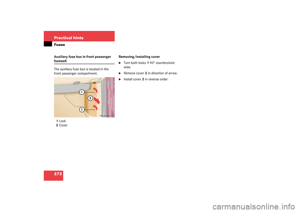
272 Practical hintsFusesAuxiliary fuse box in front passenger footwell
The auxiliary fuse box is located in the
front passenger compartment.
1Lock
2CoverRemoving/installing cover
�
Turn both locks1 90° counterclock-
wise.
�
Remove cover2 in direction of arrow.
�
Install cover2 in reverse order.