Page 89 of 370

95 Controls in detail
Memory function*
Memory function*
The memory button and stored position
switch are located on the door.
You can store up to three different settings
per key.
The following settings are saved for each
stored position:�
Driver’s seat and backrest position
�
Steering wheel position
�
Driver’s side exterior rear view mirror
position
�
Passenger side exterior rear view mir-
ror position
�
Front passenger seat position
These key-dependent memory settings
can be deactivated if desired
(
�page 127).
!Prior to operating the vehicle, the driv-
er should check and adjust the seat
height, seat position fore and aft, and
seat backrest angle if necessary, to en-
sure adequate control, reach and com-
fort. The head restraint should also be
adjusted for proper height. Also see air-
bag section (
�page 57) for proper seat
positioning.
In addition, adjust the steering wheel to
ensure adequate control, reach, opera-
tion and comfort. Both the inside and
outside rear view mirrors should be ad-
justed for adequate rear vision.
Fasten seat belts. Infants and small
children should be seated in a properly
secured restraint system that complies
with U.S. Federal Motor Vehicle Safety
Standards 213 and 225 and Canadian
Motor Vehicle Safety Standards 213
and 210.2.
Warning!
G
Do not activate the memory function while
driving. Activating the memory function
while driving could cause the driver to lose
control of the vehicle.
S203 MY03_A.book Page 95 Tuesday, January 28, 2003 2:22 PM
Page 90 of 370

96 Controls in detailMemory function*1Memory button
2Stored position button�
Make sure that the ignition is switched
on or the relevant door is open and the
SmartKey is inserted in the starter
switch.
Storing positions into memory�
Adjust the seats, steering wheel and
rear view mirrors to the desired posi-
tion (
�page 32).
�
Turn button2 to selected memory po-
sition.
�
Press memory button1.
�
Release memory button and push
button2 within three seconds.
All the settings are stored at the select-
ed position.
Recalling positions from memory�
Turn button2 to selected memory po-
sition.
�
Press and hold button2 until the seat,
steering wheel and rear view mirrors
have fully moved to the stored posi-
tions.iReleasing the button immediately
stops movement to the stored posi-
tions.Warning!
G
Do not operate the power seats using the
memory button if the seat backrest is in an
excessively reclined position. Doing so
could cause damage to front or rear seats.
First move backrest to an upright position.
S203 MY03_A.book Page 96 Tuesday, January 28, 2003 2:22 PM
Page 92 of 370

98 Controls in detailLighting
LightingFor notes on how to switch on the head-
lamps and use the turn signals, see the
“Getting started” section (
�page 47).
Exterior lamp switch
The exterior lamp switch is located on the
dashboard to the left of the steering wheel
M
Off
U
Automatic headlamp mode
C
Parking lamps (also side marker
lamps, tail lamps, license plate
lamps, instrument panel lamps)
Canada only: When engine is run-
ning, the low beam is also switched
on.
B
Low beam plus parking lamps or
high beam headlamps (combination
switch pushed forward).
ˆ
Standing lamps, right (turn left one
stop)
‚
Standing lamps, left (turn left two
stops)
iIf you remove the key and open the
driver’s door while the parking lamps or
low beam headlamps are switched on,
then �
a warning sounds
�
$
appears in the multifunction
display
�
the message
TURN OFF LAMPS
ap-
pears in the multifunction display
iWith the daytime running lamp mode
activated and the engine running, the
low beam headlamps cannot be
switched off manually.
S203 MY03_A.book Page 98 Tuesday, January 28, 2003 2:22 PM
Page 93 of 370

99 Controls in detail
Lighting
Manual headlamp mode
The low beam headlamps and parking
lamps can be switched on and off with the
exterior lamp switch. For exterior lamp
switch, see above.
Automatic headlamp mode
The parking lamps, low beam headlamps
and license plate lamps switch on and off
automatically depending on the brightness
of the ambient light.�
Turn the exterior lamp switch to
U
.
Warning!
G
In automatic headlamp mode, the head-
lamps will not be automatically switched on
under foggy conditions. To minimize risk to
you and to others, activate headlamps by
turning exterior lamp switch to
B
.
The driver is responsible for the operation of
the vehicle’s lights at all times. The automat-
ic headlamp feature is only an aid to the driv-
er. Switch on the vehicle lights manually
when driving or when traffic conditions re-
quire you to do so.
iWith the daytime running lamp mode
activated, the low beam headlamps will
not be switched off automatically.
iFront fog lamps and rear fog lamp can
not be switched on manually with exte-
rior lamp switch in position
U
. To
activate the fog lamps, turn exterior
lamp switch to position
B
.
iIf you drive in countries where vehicles
drive on the other side of the road than
the country where the vehicle is regis-
tered, you must have the headlamps
modified for symmetrical low beams.
Relevant information can be obtained
at your authorized Mercedes-Benz Cen-
ter.
S203 MY03_A.book Page 99 Tuesday, January 28, 2003 2:22 PM
Page 95 of 370

101 Controls in detail
Lighting
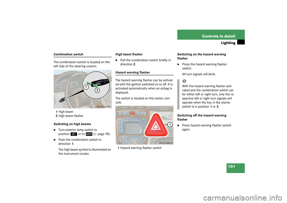
Combination switch
The combination switch is located on the
left side of the steering column.
1High beam
2High beam flasher
Switching on high beams�
Turn exterior lamp switch to
position
B
or to
U
(�page 98).
�
Push the combination switch in
direction1.
The high beam symbol is illuminated on
the instrument cluster.High beam flasher
�
Pull the combination switch briefly in
direction2.
Hazard warning flasher
The hazard warning flasher can be activat-
ed with the ignition switched on or off. It is
activated automatically when an airbag is
deployed.
The switch is located on the center con-
sole.
1Hazard warning flasher switchSwitching on the hazard warning
flasher
�
Press the hazard warning flasher
switch.
All turn signals will blink.
Switching off the hazard warning
flasher
�
Press hazard warning flasher switch
again.iWith the hazard warning flasher acti-
vated and the combination switch set
for either left or right turn, only the re-
spective left or right turn signals will
operate when the key in the starter
switch is in position1 or2.
S203 MY03_A.book Page 101 Tuesday, January 28, 2003 2:22 PM
Page 98 of 370

104 Controls in detailInstrument cluster
Instrument clusterA full view illustration of the instrument
cluster can be found in the “At a glance”
section of this manual (
�page 22).
The instrument cluster is activated when
you:
�
open a door
�
turn on the ignition
�
press the reset knob (
�page 22)
�
switch on the exterior lamps
You can change the instrument cluster set-
tings in the Instrument cluster submenu of
the control system (
�page 118).
Instrument cluster illumination
Use the reset knob (
�page 22) to adjust
the illumination brightness for the instru-
ment cluster.
To brighten illumination
�
Turn the reset knob in the instrument
cluster (
�page 22) clockwise.
The instrument cluster illumination will
brighten.To dim illumination
�
Turn the reset knob in the instrument
cluster (
�page 22) counterclockwise.
The instrument cluster illumination will
dim.
Coolant temperature display
iThe instrument cluster illumination is
dimmed or brightened automatically to
suit ambient light conditions.
The instrument cluster illumination will
also be adjusted automatically when
you switch on the vehicle’s exterior
lamps.
Warning!
G
�
Driving when your engine is badly over-
heated can cause some fluids which
may have leaked into the engine com-
partment to catch fire. You could be se-
riously burned.
�
Steam from an overheated engine can
cause serious burns and can occur just
by opening the engine hood. Stay away
f r o m t h e e n g i n e i f y o u s e e o r h e a r s t e a m
coming from it.
Turn off the engine, get out of the vehicle
and do not stand near the vehicle until it
cools down.
S203 MY03_A.book Page 104 Tuesday, January 28, 2003 2:22 PM
Page 99 of 370

105 Controls in detail
Instrument cluster
Turn the SmartKey in the starter switch to
position1 or2.�
Call up the trip odometer and main
odometer by pressing button
è
or
ÿ
on the multifunction steering
wheel (�page 108).
�
Press button
j
or
k
until the
coolant temperature display appears.During severe operating conditions and
stop-and-go city traffic, the coolant tem-
perature may rise close to 248°F (120°C).
The engine should not be operated with
the coolant temperature above 248°F
(120°C). Doing so may cause serious en-
gine damage which is not covered by the
Mercedes-Benz Limited Warranty.
Trip odometer�
Make sure you are viewing the trip
odometer and main odometer
(�page 107) in the multifunction dis-
play.
�
Press and hold the reset knob on the in-
strument cluster (
�page 22) until the
trip odometer is reset.
Tachometer
The red marking on the tachometer de-
notes excessive engine speed.
To help protect the engine, the fuel supply
is interrupted if the engine is operated
within the red marking.
iExcessive coolant temperatures trigger
a warning in the multifunction display.
!Avoid driving at excessive engine
speeds, as it may result in serious en-
gine damage that is not covered by the
Mercedes-Benz Limited Warranty.
S203 MY03_A.book Page 105 Tuesday, January 28, 2003 2:22 PM
Page 100 of 370

106 Controls in detailInstrument clusterOutside temperature indicatorThe temperature sensor is located in the
front bumper area. Due to its location, the
sensor can be affected by road or engine
heat during idling or slow driving. This
means that the accuracy of the displayed
temperature can only be verified by com-
parison to a thermometer placed next to
the sensor, not by comparison to external
displays (e.g. bank signs etc.).When moving the vehicle into colder ambi-
ent temperatures (e.g. when leaving your
garage), you will notice a delay before the
lower temperature is displayed.
A delay also occurs when ambient temper-
atures rise. This prevents inaccurate tem-
perature indications caused by heat
radiated from the engine during idling or
slow driving.Warning!
G
The outside temperature indicator is not de-
signed to serve as an ice-warning device and
is therefore unsuitable for that purpose.
Indicated temperatures just above the freez-
ing point do not guarantee that the road sur-
face is free of ice. The road may still be icy,
especially in wooded areas or on bridges.
S203 MY03_A.book Page 106 Tuesday, January 28, 2003 2:22 PM