Page 282 of 376
282 Practical hintsWhere will I find ...?Storing the spare wheel�
Place spare wheel2 in wheel well.
�
Turn storage tray3 clockwise to its
stop to secure the spare wheel.
�
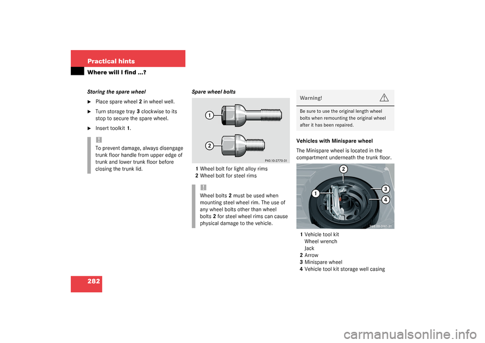
Insert toolkit1.Spare wheel bolts
1Wheel bolt for light alloy rims
2Wheel bolt for steel rimsVehicles with Minispare wheel
The Minispare wheel is located in the
compartment underneath the trunk floor.
1Vehicle tool kit
Wheel wrench
Jack
2Arrow
3Minispare wheel
4Vehicle tool kit storage well casing!To prevent damage, always disengage
trunk floor handle from upper edge of
trunk and lower trunk floor before
closing the trunk lid.
!Wheel bolts2 must be used when
mounting steel wheel rim. The use of
any wheel bolts other than wheel
bolts2 for steel wheel rims can cause
physical damage to the vehicle.
Warning!
G
Be sure to use the original length wheel
bolts when remounting the original wheel
after it has been repaired.
Page 284 of 376
284 Practical hintsWhere will I find ...?In the case of a flat tire, you may
temporarily use the Minispare wheel when
observing the following restrictions:�
Do not exceed a vehicle speed of
50 mph (80 km/h).
�
Drive to the nearest tire repair facility
to have the flat tire repaired or
replaced as appropriate.
�
Do not operate vehicle with more than
one Minispare wheel mounted.Minispare wheel bolts
1Wheel bolt for light alloy rims
2Wheel bolt for Minispare wheel or other
steel rims
!Wheel bolts2 must be used when
mounting the Minispare wheel. The use
of any wheel bolts other than wheel
bolts2 for the Minispare wheel can
cause physical damage to the vehicle.
Warning!
G
Be sure to use the original length wheel
bolts when remounting the original wheel
after it has been repaired.
Page 291 of 376

291 Practical hints
Replacing bulbs
Rear lamps Notes on bulb replacement
�
Use only 12 volt bulbs of the same type
and with the specified watt rating.
�
Switch lights off before changing a bulb
to prevent short circuits.
�
Always use a clean lint-free cloth when
handling bulbs.
�
Your hands should be dry and free of oil
and grease.
�
If the newly installed bulb does not light
up, visit an authorized Mercedes-Benz
Center.
�
Have the LEDs and bulbs for the follow-
ing lamps replaced by an authorized
Mercedes-Benz Center:�
Additional turn signal lamps in the
exterior rear view mirrors
�
High mounted brake lamp
�
Xenon lamps
�
Front fog lamps
Lamp
Type
7
High mounted brake
lamp
LED
8
Brake lamp
P21W
9
Turn signal lamp
PY 21 W
10
Backup lamp
P21W
11
Tail, parking,
standing and side
marker lamp
R5W
12
License plate lamps
C5W
13
Rear fog lamp,
driver’s side
P21W
Warning!
G
Keep bulbs out of reach of children.
Bulbs and bulb sockets can be very hot. Al-
low the lamp to cool down before changing
a bulb.
Halogen lamps contain pressurized gas.
A bulb can explode if you�
touch or move it when hot
�
drop the bulb
�
scratch the bulb
Wear eye and hand protection.
Because of high voltage in Xenon lamps, it is
dangerous to replace the bulb or repair the
lamp and its components. We recommend
that you have such work done by a qualified
technician.
Page 293 of 376
.
�
Press the clamp and remove headlamp
cover2.
�
Pull out the bulb socket6 with")
293 Practical hints
Replacing bulbs
Parking and standing lamp bulb�
Switch off the lights.
�
Open the hood (
�page 235).
�
Press the clamp and remove headlamp
cover2.
�
Pull out the bulb socket6 with the
bulb.
�
Pull the bulb out of the bulb socket.
�
Insert a new bulb in the socket.
�
Reinstall the bulb socket.
�
Align headlamp cover2 and click into
place.Bi-Xenon* headlamps
1Bulb socket for turn signal lamp
2Headlamp cover for high beam head-
lamp, parking and standing lamp
3Headlamp cover for Bi-Xenon lamp4High beam headlamp bulb
5Bayonet socket for high beam
headlamp bulb
6Bulb socket for parking and standing
lamp bulb
High beam bulb
�
Switch off the lights.
�
Open the hood (
�page 235).
�
Press the clamp and remove headlamp
cover2.
�
Pull electrical connector4 off.
Warning!
G
Do not remove the cover3 for the Bi-Xenon
headlamp. Because of high voltage in
Bi-Xenon lamps, it is dangerous to replace
the bulb or repair the lamp and its compo-
nents. We recommend that you have such
work done by a qualified technician.
��
Page 300 of 376

300 Practical hintsFlat tire
�
Unscrew the alignment bolt, install last
wheel bolt and tighten slightly.Minispare wheel
Warning!
G
Always replace wheel bolts that are
damaged or rusted.
Never apply oil or grease to wheel bolts.
Damaged wheel hub threads should be
repaired immediately. Do not continue to
drive under these circumstances! Contact
an authorized Mercedes-Benz Center or call
Roadside Assistance.
Incorrect mounting bolts or improperly
tightened mounting bolts can cause the
wheel to come off. This could cause an
accident. Be sure to use the correct mount-
ing bolts.
Warning!
G
Use only genuine equipment
Mercedes-Benz wheel bolts. They are identi-
fied by the Mercedes star. Other wheel bolts
may come loose.
Do not tighten the wheel bolts when the
vehicle is raised. Otherwise the vehicle
could tip over.
Warning!
G
The dimensions of the Minispare wheel are
different from those of the road wheels. As
a result, the vehicle handling characteristics
change when driving with a Minispare wheel
mounted.
The spare wheel should only be used
temporarily, and replaced with a regular
road wheel as quick as possible.
Page 307 of 376

307 Practical hints
Jump starting
The battery is located in the engine
compartment on the right hand side. The
terminals for jump starting are located in
front of the battery.�
Make sure that the two vehicles do not
touch.
�
Turn off all electrical consumers.
�
Apply parking brake.
�
Shift selector lever to positionP (man-
ual transmission to Neutral).1Positive terminal of charged battery
2Positive under hood terminal in front of
discharged battery
3Negative terminal of charged battery
4Negative under hood terminal in front
of discharged battery
�
Connect positive terminal1 of the
charged battery with the under hood
terminal2 in front of the discharged
battery with the jumper cables. Clamp
cable to charged battery1 first.
�
Start engine of the vehicle with the
charged battery and run at idle speed.
�
Connect negative terminal3 of the
charged battery with the under hood
terminal4 of the discharged battery
with the jumper cables. Clamp cable to
charged battery3 first.
�
Start the engine of the disabled vehi-
cle.
Now you can again turn on the electrical
consumers. Do not turn on the lights under
any circumstances.
�
Remove the jumper cables first from
negative terminals3 and4 and then
from positive terminals1 and2.
�
Have the battery checked at the near-
est authorized Mercedes-Benz Center.
Warning!
G
Keep flames or sparks away from battery.
Do not smoke.
Observe all safety instructions and precau-
tions when handling automotive batteries
(�page 240).
!Vehicles with automatic transmission
and/or 4MATIC*:
Do not tow-start the vehicle.
Page 341 of 376

Prevents the wheels from locking up
during braking so that the vehicle can
continue to be steered.
Alignment bolt
Metal pin with thread. The center")
341 Technical terms
ABS
(A
ntilock B
rake S
ystem)
Prevents the wheels from locking up
during braking so that the vehicle can
continue to be steered.
Alignment bolt
Metal pin with thread. The centering
pin is an aid used when changing a tire
to align the wheel with the wheel hub.
BabySmart
TM
airbag deactivation
system
This system detects if a special system
compatible child restraint seat is in-
stalled on the front passenger seat. The
system will automatically deactivate
the passenger front airbag when such a
seat is properly installed (indicator
lamp
7
located in the center con-
sole lights up). See your authorized
Mercedes-Benz Center for availability. BabySmart
TM
compatible child seats
Special restraint system for children.
The sensor system for the passenger
seat prevents deployment of the pas-
senger side airbag if a BabySmart
TM
compatible child seat is installed.
BAS
(B
rake A
ssist S
ystem)
System for potentially reducing braking
distances in emergency braking situa-
tions. The system is activated when it
senses an emergency based on how
fast the brake is applied.
Bi-Xenon headlamps*
Headlamps which use an electric arc as
the light source and produce a more
intense light than filament headlamps.
Bi-Xenon headlamps produce low
beam and high beam.CAC
(C
ustomer A
ssistance C
enter)
Mercedes-Benz customer service cen-
ter, which can help you with any ques-
tions about your vehicle and provide
assistance in the event of a break-
down.
CAN system
(C
ontroller A
rea N
etwork)
Data bus network serving to control
vehicle functions such as door locking
or windshield wiping.
Cockpit
All instruments, switches, buttons and
indicator/warning lamps in the passen-
ger compartment needed for vehicle
operation and monitoring.
Page 351 of 376

351 Index
Climate control 148
Adjusting 151
Defogging windshield 151
Defrosting 151
Setting the temperature 150
Clock 23, 122
Closing
Glove box 203
Hood 236
Side windows 187
Sliding/pop-up roof* 190, 289
Sliding/pop-up roof*
with SmartKey 191
Trunk lid 89
Windows 187
Windows with SmartKey 188
Closing sliding/pop-up roof*
In an emergency 289
Cockpit 20, 341
Cockpit management and data system
(COMAND*) 342
COMAND* see separate operating
instructionsCombination switch 104
High beam flasher 47
Turn signals 47
Windshield wipers 48
Consumer information 339
Control and operation of radio
transmitters 230
Control system 111, 342
AUDIO menu 116
Convenience submenu 129
Display digital speedometer 116
Functions 112, 115
Instrument cluster submenu 122
Lighting submenu 125
Malfunction memory menu 118
Menus 114, 115, 343
Multifunction display 111
Multifunction steering wheel 112
NAVI menu* 118
Selecting radio system 117
Settings menu 119
Standard display menu 116
Submenus 113, 115
TEL* menu 134
Trip computer menu 132
Vehicle submenu 128Convenience submenu 129
Activating easy-entry/exit
feature* 129
Setting key dependency 131
Setting parking position* for
exterior rear view mirror 131
Coolant 238, 336
Adding 239
Anticorrosion/antifreeze
quantity 336
Capacities 329
Checking level 238
Messages in display 266, 267
Temperature 232
Temperature display 108
Warning lamp 267
Coolant level
Checking 234, 238
Cruise control 193, 342
Canceling 194
Driving downhill 194
Driving uphill 194
Fine adjustment 195
Saving current speed 194
Setting speeds 195
Cruise control lever 193