Page 1770 of 4500
in the warning area.
SFI (EFI) system (see SYSTEM DIAGRAM )
VSC system (see HOW TO PROCEED WITH TROUBLESHOOTING )
CRUISE system (see HOW TO PROCEED WITH TROUBLESHOOTING)
Page 1782 of 4500

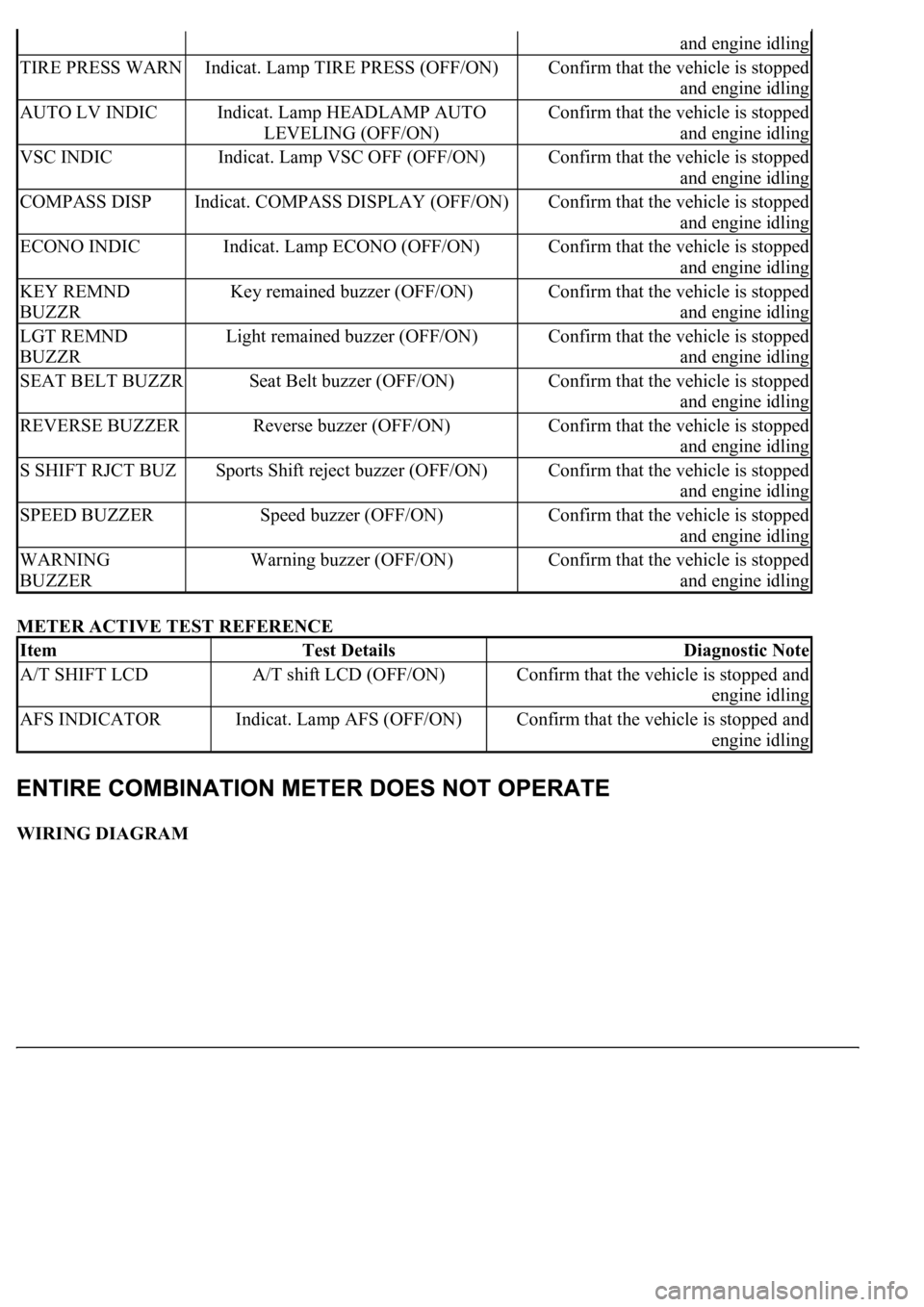
METER ACTIVE TEST REFERENCE
WIRING DIAGRAM
and engine idling
TIRE PRESS WARNIndicat. Lamp TIRE PRESS (OFF/ON)Confirm that the vehicle is stopped
and engine idling
AUTO LV INDICIndicat. Lamp HEADLAMP AUTO
LEVELING (OFF/ON)Confirm that the vehicle is stopped
and engine idling
VSC INDICIndicat. Lamp VSC OFF (OFF/ON)Confirm that the vehicle is stopped
and engine idling
COMPASS DISPIndicat. COMPASS DISPLAY (OFF/ON)Confirm that the vehicle is stopped
and engine idling
ECONO INDICIndicat. Lamp ECONO (OFF/ON)Confirm that the vehicle is stopped
and engine idling
KEY REMND
BUZZRKey remained buzzer (OFF/ON)Confirm that the vehicle is stopped
and engine idling
LGT REMND
BUZZRLight remained buzzer (OFF/ON)Confirm that the vehicle is stopped
and engine idling
SEAT BELT BUZZRSeat Belt buzzer (OFF/ON)Confirm that the vehicle is stopped
and engine idling
REVERSE BUZZERReverse buzzer (OFF/ON)Confirm that the vehicle is stopped
and engine idling
S SHIFT RJCT BUZSports Shift reject buzzer (OFF/ON)Confirm that the vehicle is stopped
and engine idling
SPEED BUZZERSpeed buzzer (OFF/ON)Confirm that the vehicle is stopped
and engine idling
WARNING
BUZZERWarning buzzer (OFF/ON)Confirm that the vehicle is stopped
and engine idling
ItemTest DetailsDiagnostic Note
A/T SHIFT LCDA/T shift LCD (OFF/ON)Confirm that the vehicle is stopped and
engine idling
AFS INDICATORIndicat. Lamp AFS (OFF/ON)Confirm that the vehicle is stopped and
engine idling
Page 1783 of 4500
Fig. 43: Combination Meter Wiring Diagram
Courtesy of TOYOTA MOTOR SALES, U.S.A., INC.
INSPECT PROCEDURE
1.INSPECT COMBINATION METER ASSY
a. Measure the resistance according to the value (s) in the table below.
Standard
COMBINATION METER RESISTANCE SPECIFICATIONS
Terminal NoConditionSpecified condition
Page 1785 of 4500
WIRING DIAGRAM
Fig. 45: Speedometer Wiring Diagram
Courtesy of TOYOTA MOTOR SALES, U.S.A., INC.
INSPECTION PROCEDURE
1.PERFORM ACTIVE TEST BY HAND-HELD TESTER
a. Operate the hand-held tester according to the steps on the display and select the "ACTIVE TEST".
METER:
SPEED METER ACTIVE TEST REFERENCE
OK:
Needle indication is normal.
NG: REPLACE COMBINATION METER ASSY (SEE OVERHAUL
)
OK: GO TO NEXT STEP
2.READ VALUE OF HAND-HELD TESTER (VEHICLE SPEED SIGNAL)
a. Operate the han
d-held tester according to the steps on the display and select the "DATA LIST"
ItemTest DetailsDiagnostic
Note
SPEED
METER0 / 40(24) / 80(48) / 120(72) / 1 60(96) / 180(108) / 200(120) km/h
(mph)-
Page 1792 of 4500
WIRING DIAGRAM
Fig. 50: Tachometer Wiring Diagram
Courtesy of TOYOTA MOTOR SALES, U.S.A., INC.
INSPECTION PROCEDURE
1.PERFORM ACTIVE TEST BY HAND-HELD TESTER
a. Operate the hand-held tester according to the steps on the display and select the "ACTIVE TEST".
METER:
TACHO METER ACTIVE TEST REFERENCE
OK:
Needle indication is normal.
NG: REPLACE COMBINATION METER ASSY (SEE OVERHAUL
)
OK: GO TO NEXT STEP
2.READ VALUE OF HAND-HELD TESTER (ENGINE SPEED SIGNAL)
a. Operate the han
d-held tester according to the steps on the display and select the "DATA LIST".
ItemTest DetailsDiagnostic
Note
TACHOMETEROrpm / 1000rpm / 2000rpm / 3000rpm / 4000rpm / 5000rpm /
6000rpm / 7000rpm-
Page 1798 of 4500
Courtesy of TOYOTA MOTOR SALES, U.S.A., INC.
OK: GO TO ENGINE CONTROL SYSTEM (SEE REPLACEMENT
)
WIRING DIAGRAM
Fig. 55: Fuel Receiver Gauge Wiring Diagram
Courtesy of TOYOTA MOTOR SALES, U.S.A., INC.
INSPECTION PROCEDURE
1.PERFORM ACTIVE TEST BY HAND-HELD TESTER
a. Operate the hand-held tester according to the steps on the display and select the "ACTIVE TEST".
METER:
METER ACTIVE TEST REFERENCE
OK:
Needle indication is normal.
NG: REPLACE COMBINATION METER ASSY (SEE OVERHAUL
)
ItemTest DetailsDiagnostic Note
FUEL GAUGEOFF, EMPTY, 1/2, FULL-
Page 1810 of 4500
Fig. 63: Identifying Fuel Sender Gauge Assy And Luggage Room Junction Block Assy Connector
Terminals
Courtesy of TOYOTA MOTOR SALES, U.S.A., INC.
NG: REPAIR OR REPLACE HARNESS OR CONNECTOR
OK: REPLACE LUGGAGE ROOM JUNCTION BLOCK ASSY
WIRING DIAGRAM
Fig. 64: Water Temperature Receiver Gauge Wiring Diagram
Courtesy of TOYOTA MOTOR SALES, U.S.A., INC.
INSPECTION PROCEDURE
HINT:
If there is an open or short in the engine coolant temperature sensor circuit, the ECM outputs DTCs. Perform
troubleshooting with the "SFI System 10-2".
1.PERFORM ACTIVE TEST BY HAND-HELD TESTER
a. Operate the hand-held tester according to the steps on the display and select the "ACTIVE TEST".
METER:
ACTIVE TEST REFERENCE
Page 1811 of 4500
OK:
Needle indication is normal.
NG: REPLACE COMBINATION METER ASSY (SEE OVERHAUL
)
OK: GO TO NEXT STEP
2.READ VALUE OF HAND-HELD TESTER (ENGINE COOLANT)
a. Operate the hand-held tester according to the steps on the display and select the "DATA LIST".
ENGINE:
DATA LIST REFERENCE
OK:
Coolant temperature displayed on the tester is between 80°C (176°F) and 95°C (203°F) after
warning up.
NG: GO TO ENGINE CONTROL SYSTEM (SEE REPLACEMENT
)
OK: GO TO NEXT STEP
3.REPLACE COMBINATION METER ASSY
OK:
Normal operation
NG: GO TO ENGINE CONTROL SYSTEM (SEE REPLACEMENT
)
OK: END
WIRING DIAGRAM
ItemTest DetailsDiagnostic Note
COOLANT TEMPLOW /NORMAL /HI-
ItemMeasurement Item/ Range
(Display)Normal ConditionDiagnostic Note
COOLANT
TEMPCoolant Temperature / Min.: -
40°C (-40°F), Max.: 140°C
(284 °F)After warming up: 80
to 95°C (176 to 203°
F)If the value is "-40°C (-40°F)" or
"140°C (284°F)", sensor circuit is
open or shorted.