2003 JEEP GRAND CHEROKEE floor jack
[x] Cancel search: floor jackPage 17 of 2199
DESCRIPTION - ENGINE OIL - DIESEL
ENGINES
Use only Diesel Engine Oil meeting standardMIL-
2104Cor API ClassificationCD or higherorCCML
D4, D5.
SAE VISCOSITY GRADE
CAUTION: Low viscosity oils must have the proper
API quality or the CCMC G5 designation.
To assure of properly formulated engine oils, it is
recommended that SAE Grade 10W-40 engine oils
that meet Chrysler material standard MS-6395, be
used. European Grade 10W-40 oils are also accept-
able.
Oils of the SAE 5W-40 or 8W-80 grade number are
preferred when minimum temperatures consistently
fall below -12ÉC.
OPERATION - AUTOMATIC TRANSMISSION
FLUID
The automatic transmission fluid is selected based
upon several qualities. The fluid must provide a high
level of protection for the internal components by
providing a lubricating film between adjacent metal
components. The fluid must also be thermally stable
so that it can maintain a consistent viscosity through
a large temperature range. If the viscosity stays con-
stant through the temperature range of operation,
transmission operation and shift feel will remain con-
sistent. Transmission fluid must also be a good con-
ductor of heat. The fluid must absorb heat from the
internal transmission components and transfer that
heat to the transmission case.
FLUID FILL/CHECK
LOCATIONS
INSPECTION - FLUID FILL/CHECK LOCATIONS
The fluid fill/check locations and lubrication points
are located in each applicable group.
MAINTENANCE SCHEDULES
DESCRIPTION
9Maintenance Schedule Information not included in
this section, is located in the appropriate Owner's
Manual.9
LIFT POINTS
STANDARD PROCEDURE - HOISTING AND
JACKING RECOMMENDATIONS
FLOOR JACK
When properly positioned, a floor jack can be used
to lift a WJ vehicle (Fig. 7). Support the vehicle in
the raised position with jack stands at the front and
rear ends of the frame rails.
CAUTION: Do not attempt to lift a vehicle with a
floor jack positioned under:
²An axle tube.
²Aluminum differential.
²A body side sill.
²A steering linkage component.
²A drive shaft.
²The engine or transmission oil pan.
²The fuel tank.
²A front suspension arm.
HOIST
A vehicle can be lifted with:
²A single-post, frame-contact hoist.
²A twin-post, chassis hoist.
²A ramp-type, drive-on hoist.
NOTE: When a frame-contact type hoist is used,
verify that the lifting pads are positioned properly
(Fig. 7).
WARNING: THE HOISTING AND JACK LIFTING
POINTS PROVIDED ARE FOR A COMPLETE VEHI-
CLE. WHEN A CHASSIS OR DRIVETRAIN COMPO-
NENT IS REMOVED FROM A VEHICLE, THE
CENTER OF GRAVITY IS ALTERED MAKING SOME
HOISTING CONDITIONS UNSTABLE. PROPERLY
SUPPORT OR SECURE VEHICLE TO HOISTING
DEVICE WHEN THESE CONDITIONS EXIST.
0 - 6 LUBRICATION & MAINTENANCEWJ
FLUID TYPES (Continued)
Page 467 of 2199

ness connector for the multi-function switch and the
instrument panel wire harness connector for the
BCM. There should be continuity. If OK, go to Step 3.
If not OK, repair the open headlamp switch mux cir-
cuit.
(3) Check for continuity between the headlamp
switch return circuit of the instrument panel wire
harness connector for the multi-function switch and a
good ground. There should be no continuity. If OK, go
to Step 4. If not OK, repair the shorted headlamp
switch return circuit.
(4) Check for continuity between the headlamp
switch return circuit of the instrument panel wire
harness connector for the multi-function switch and
the instrument panel wire harness connector for the
BCM. There should be continuity. If OK, use a
DRBIIItscan tool and the proper Diagnostic Proce-
dures manual to test the BCM. If not OK, repair the
open headlamp switch return circuit.
HEADLAMP UNIT
REMOVAL
(1) Remove the jack screw attaching the top of
headlamp to the headlamp mounting module (Fig.
14).
(2) Grasp upper inboard and lower outboard cor-
ners of headlamp (Fig. 15) and pull headlamp out-
ward.
(3) Remove all of the bulb sockets from headlamp
module.
(4) Separate the headlamp from vehicle.
INSTALLATION
CAUTION: Do not touch the bulb glass with fingers
or other oily surfaces. Reduced bulb life will result.
(1) Install all of the bulb sockets in headlamp mod-
ule.
(2) Position the headlamp on the vehicle and align
the ball studs with the sockets.
(3) Push the headlamp inward to secure the ball
studs with the sockets.
(4) Install the jack screw attaching the top of
headlamp to the headlamp mounting module.
ADJUSTMENTS
VEHICLE PREPARATION FOR LAMP ALIGNMENT
(1) Verify headlamp dimmer switch and high beam
indicator operation.
(2) Correct defective components that could hinder
proper lamp alignment.
(3) Verify proper tire inflation.
(4) Clean lamp lenses.
(5) Verify that luggage area is not heavily loaded.
(6) Fuel tank should be FULL. Add 2.94 kg (6.5
lbs.) of weight over the fuel tank for each estimated
gallon of missing fuel.
LAMP ALIGNMENT SCREEN PREPARATION
(1) Position vehicle on a level surface perpendicu-
lar to a flat wall 7.62 meters (25 ft) away from front
of headlamp lens (Fig. 16).
(2) If necessary, tape a line on the floor 7.62
meters (25 ft) away from and parallel to the wall.
(3) Measure from the floor up 1.27 meters (5 ft)
and tape a line on the wall at the centerline of the
vehicle. Sight along the centerline of the vehicle
Fig. 14 Headlamp Jackscrew
1 - JACKSCREW
2 - HEADLAMP
Fig. 15 Headlamp Removal
1 - HEADLAMP
8L - 16 LAMPS/LIGHTING - EXTERIORWJ
HEADLAMP SWITCH (Continued)
Page 1255 of 2199

(7) Remove the fan assembly from the water pump
(Refer to 7 - COOLING/ENGINE/RADIATOR FAN -
REMOVAL).
(8) Remove the fan shroud.
(9) Disconnect the transmission fluid cooler lines
(automatic transmission).
(10) Discharge the A/C system (Refer to 24 -
HEATING & AIR CONDITIONING/PLUMBING -
STANDARD PROCEDURE).
(11) Remove the service valves and cap the com-
pressor ports.
(12) Remove the radiator or radiator/condenser (if
equipped with A/C).
(13) Disconnect the heater hoses at the engine
thermostat housing and water pump.
(14) Disconnect the accelerator cable, transmission
line pressure cable and speed control cable (if
equipped) from the throttle body.
(15) Remove cables from the bracket and secure
out of the way.
(16) Disconnect the body ground at the engine.
(17) Disconnect the following connectors and
secure their harness out of the way.
²Power steering pressure switch
²Coolant temperature sensor
²Six (6) fuel injector connectors
²Intake air temperature sensor
²Throttle position sensor
²Map sensor
²Crankshaft position sensor
²Oxygen sensor
²Camshaft position sensor
²Generator connector and B+ terminal wire
(18) Disconnect the coil rail electrical connections
and the oil pressure switch connector.
(19) Perform the fuel pressure release procedure
(Refer to 14 - FUEL SYSTEM/FUEL DELIVERY -
STANDARD PROCEDURE).
(20) Disconnect the fuel supply line at the injector
rail (Refer to 14 - FUEL SYSTEM/FUEL DELIVERY/
QUICK CONNECT FITTING - STANDARD PROCE-
DURE).
(21) Remove the fuel line bracket from the intake
manifold.
(22) Remove the air cleaner assembly (Fig. 5).
(23) Disconnect the hoses from the fittings at the
steering gear.
(24) Drain the pump reservoir.
(25) Cap the fittings on the hoses and steering
gear to prevent foreign objects from entering the sys-
tem.
(26) Raise and support the vehicle.
(27) Disconnect the wires from the engine starter
motor solenoid.(28) Remove the engine starter motor (Refer to 8 -
ELECTRICAL/STARTING/STARTER MOTOR -
REMOVAL).
(29) Disconnect the oxygen sensor from the
exhaust pipe.
(30) Disconnect the exhaust pipe from the mani-
fold.
(31) Remove the exhaust pipe support.
(32) Remove the bending brace (Refer to 9 -
ENGINE/ENGINE BLOCK/STRUCT SUPPORT -
REMOVAL).
(33) Remove the engine flywheel/converter housing
access cover.
(34) Mark the converter and drive plate location.
(35) Remove the converter-to-drive plate bolts.
(36) Remove the upper engine flywheel/converter
housing bolts and loosen the bottom bolts.
(37) Remove the engine mount cushion-to-engine
compartment bracket bolts.
(38) Lower the vehicle.
(39) Attach a lifting device to the engine.
(40) Raise the engine off the front supports.
(41) Place a support or floor jack under the con-
verter (or engine flywheel) housing.
(42) Remove the remaining converter (or engine
flywheel) housing bolts.
(43) Lift the engine out of the engine compart-
ment.
Fig. 5 Air Cleaner Assembly
1 - POWER STEERING PUMP
2 - AIR CLEANER ASSEMBLY
9 - 12 ENGINE - 4.0LWJ
ENGINE - 4.0L (Continued)
Page 1439 of 2199
(19) Disconnect fuel return line at fuel filter/fuel
pressure regulator (Fig. 36). Refer to Quick-Connect
Fittings for procedures.
(20) Disconnect fuel pressure line at fuel filter/fuel
pressure regulator (Fig. 36). Refer to Quick-Connect
Fittings for procedures.
(21) Disconnect EVAP canister vent line near front
of tank (Fig. 36).
(22) Disconnect fuel pump module electrical con-
nector (pigtail harness) near front of tank (Fig. 36).
Harness connector is clipped to body.
(23) Remove left / front tank support bracket bolt
at frame (Fig. 37).
(24)WITHOUT TRAILER HITCH:Remove tank-
to-frame mounting bolts (Fig. 39). Remove rear tank
support bracket bolts at frame (Fig. 38). Carefully
lower tank until clear of vehicle. Place tank on floor.
(25)WITH TRAILER HITCH:Remove tank /
hitch mounting bolts (Fig. 40). Carefully lower tank
until clear of vehicle. Place tank on floor.
(26) If necessary, separate skid plate from fuel
tank by removing 2 fuel tank strap nuts (Fig. 39) and
remove 2 tank straps.
(27) If fuel pump module removal is necessary,
refer to Fuel Pump Module Removal/Installation.
(28) If hoses are to be removed at fuel tank end,
note painted alignment (indexing) markings on
hoses, and molded indexing tangs on tank before
removal. Remove hoses.
(29) If necessary, remove 3 fuel filler tube assem-
bly mounting bolts (Fig. 41) and remove fuel filler
tube.
INSTALLATION
CAUTION: HANDLE EVAP, LDP AND ORVR VAPOR /
VACUUM LINES VERY CAREFULLY. THESE LINES
AND HOSES MUST BE FIRMLY CONNECTED.
CHECK THE VAPOR/VACUUM LINES AT THE LDP,
LDP FILTER, EVAP CANISTER, EVAP CANISTER
PURGE SOLENOID AND ORVR COMPONENTS FOR
DAMAGE OR LEAKS. IF A LEAK IS PRESENT, A
DIAGNOSTIC TROUBLE CODE (DTC) MAY BE SET.
(1) If necessary, position fuel filler tube assembly
to body. Install 3 bolts and tighten to 2 N´m (15 in.
lbs.) torque.
(2) If necessary, connect quick-connect fittings to
fuel pump module.
(3) If fuel pump module is being installed, refer to
Fuel Pump Module Removal/Installation.
(4) Install fuel fill/vent hoses to tank fittings. To
prevent hoses from kinking, rotate each hose until
painted indexing mark on hose is aligned to molded
indexing tang on tank.
(5) Install hose clamps to hoses. Refer to Torque
Specifications.(6) If necessary, position fuel tank into skid plate.
Install 2 tank straps and 2 strap nuts (Fig. 39). Refer
to Torque Specifications.
(7) Position fuel tank / skid plate assembly to
hydraulic jack.
(8) Raise tank into position to frame.
(9)WITH TRAILER HITCH:Position trailer
hitch and tow hooks (Fig. 40) to bottom of fuel tank.
Install bolts and nuts loosely.
(10)WITHOUT TRAILER HITCH:Install 2 rear
tank support brackets and bolts (Fig. 38). Install
tank-to-frame bolts. Do not tighten bolts / nuts at
this time.
(11) Install 1 left / front tank support bracket and
bolts / nuts (Fig. 37). Do not tighten bolts / nuts at
this time.
(12) Be sure fuel tank is properly aligned to frame
and body. Tighten all tank, tow hook and trailer
hitch bolts / nuts except for 3 support brackets.
Tighten all 3 (2 rear and 1 left / front) support
bracket bolts / nuts last. Refer to Torque Specifica-
tions.
(13)
(14) Connect fuel pump module pigtail harness
electrical connector near front of tank.
(15) Connect both fuel lines to fuel filter/fuel pres-
sure regulator. Refer to Quick-Connect Fittings for
procedures.
(16) Connect EVAP hose near front of tank.
(17) Position rear axle vent hose and install new
tie strap (Fig. 32).
(18) Install heat shield nuts / bolts (Fig. 35). Refer
to Torque Specifications.
(19) Connect ORVR hose elbow (Fig. 33) to top of
EVAP canister.
(20) Connect fuel vent hose to fuel vent tube (Fig.
32).
(21) Install fuel fill hose and clamp to fuel fill tube
(Fig. 32).
(22) Install 3 LDP mounting bolts (Fig. 29).
(23) While raising support bracket, connect LDP
wiring clip (Fig. 31). Install front section of two-piece
support bracket to rear section with 3 attaching bolts
located on bottom of support bracket (Fig. 30).
(24) Install support bracket brace bolt (Fig. 30).
(25) Tighten 2 support bracket nuts at frame rail
(Fig. 29).
(26) Install fuel tank-to-rear bumper fascia clips
(Fig. 34).
(27) Using new plastic rivets, install stone shield
behind left/rear wheel (Fig. 28).
(28) Install left rear wheel/tire.
(29) Lower vehicle and connect negative battery
cable to battery.
(30) Fill tank with fuel and check for leaks.
14 - 20 FUEL DELIVERYWJ
FUEL TANK (Continued)
Page 1630 of 2199
FORCE MULTIPLICATION
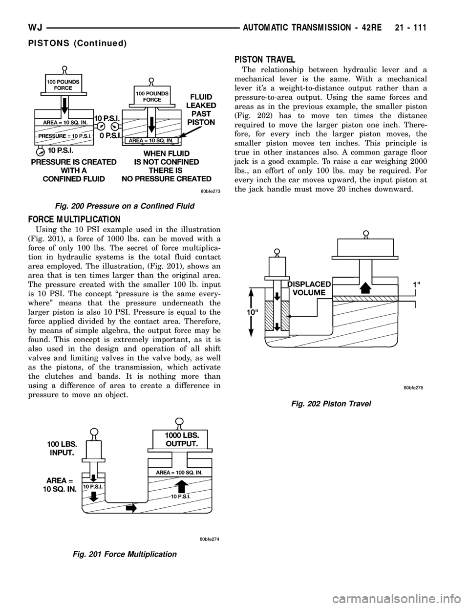
Using the 10 PSI example used in the illustration
(Fig. 201), a force of 1000 lbs. can be moved with a
force of only 100 lbs. The secret of force multiplica-
tion in hydraulic systems is the total fluid contact
area employed. The illustration, (Fig. 201), shows an
area that is ten times larger than the original area.
The pressure created with the smaller 100 lb. input
is 10 PSI. The concept ªpressure is the same every-
whereº means that the pressure underneath the
larger piston is also 10 PSI. Pressure is equal to the
force applied divided by the contact area. Therefore,
by means of simple algebra, the output force may be
found. This concept is extremely important, as it is
also used in the design and operation of all shift
valves and limiting valves in the valve body, as well
as the pistons, of the transmission, which activate
the clutches and bands. It is nothing more than
using a difference of area to create a difference in
pressure to move an object.
PISTON TRAVEL
The relationship between hydraulic lever and a
mechanical lever is the same. With a mechanical
lever it's a weight-to-distance output rather than a
pressure-to-area output. Using the same forces and
areas as in the previous example, the smaller piston
(Fig. 202) has to move ten times the distance
required to move the larger piston one inch. There-
fore, for every inch the larger piston moves, the
smaller piston moves ten inches. This principle is
true in other instances also. A common garage floor
jack is a good example. To raise a car weighing 2000
lbs., an effort of only 100 lbs. may be required. For
every inch the car moves upward, the input piston at
the jack handle must move 20 inches downward.
Fig. 200 Pressure on a Confined Fluid
Fig. 201 Force Multiplication
Fig. 202 Piston Travel
WJAUTOMATIC TRANSMISSION - 42RE 21 - 111
PISTONS (Continued)
Page 1776 of 2199
FORCE MULTIPLICATION
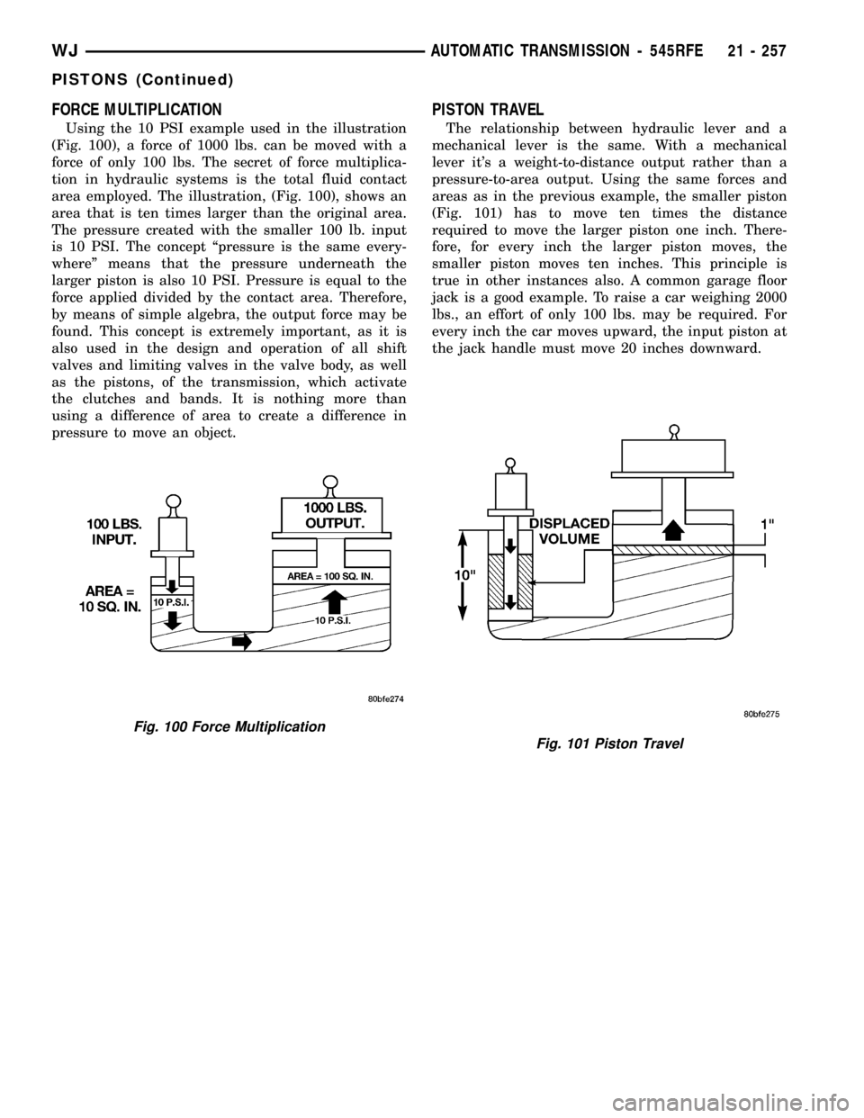
Using the 10 PSI example used in the illustration
(Fig. 100), a force of 1000 lbs. can be moved with a
force of only 100 lbs. The secret of force multiplica-
tion in hydraulic systems is the total fluid contact
area employed. The illustration, (Fig. 100), shows an
area that is ten times larger than the original area.
The pressure created with the smaller 100 lb. input
is 10 PSI. The concept ªpressure is the same every-
whereº means that the pressure underneath the
larger piston is also 10 PSI. Pressure is equal to the
force applied divided by the contact area. Therefore,
by means of simple algebra, the output force may be
found. This concept is extremely important, as it is
also used in the design and operation of all shift
valves and limiting valves in the valve body, as well
as the pistons, of the transmission, which activate
the clutches and bands. It is nothing more than
using a difference of area to create a difference in
pressure to move an object.
PISTON TRAVEL
The relationship between hydraulic lever and a
mechanical lever is the same. With a mechanical
lever it's a weight-to-distance output rather than a
pressure-to-area output. Using the same forces and
areas as in the previous example, the smaller piston
(Fig. 101) has to move ten times the distance
required to move the larger piston one inch. There-
fore, for every inch the larger piston moves, the
smaller piston moves ten inches. This principle is
true in other instances also. A common garage floor
jack is a good example. To raise a car weighing 2000
lbs., an effort of only 100 lbs. may be required. For
every inch the car moves upward, the input piston at
the jack handle must move 20 inches downward.
Fig. 100 Force Multiplication
Fig. 101 Piston Travel
WJAUTOMATIC TRANSMISSION - 545RFE 21 - 257
PISTONS (Continued)
Page 1885 of 2199
DOOR
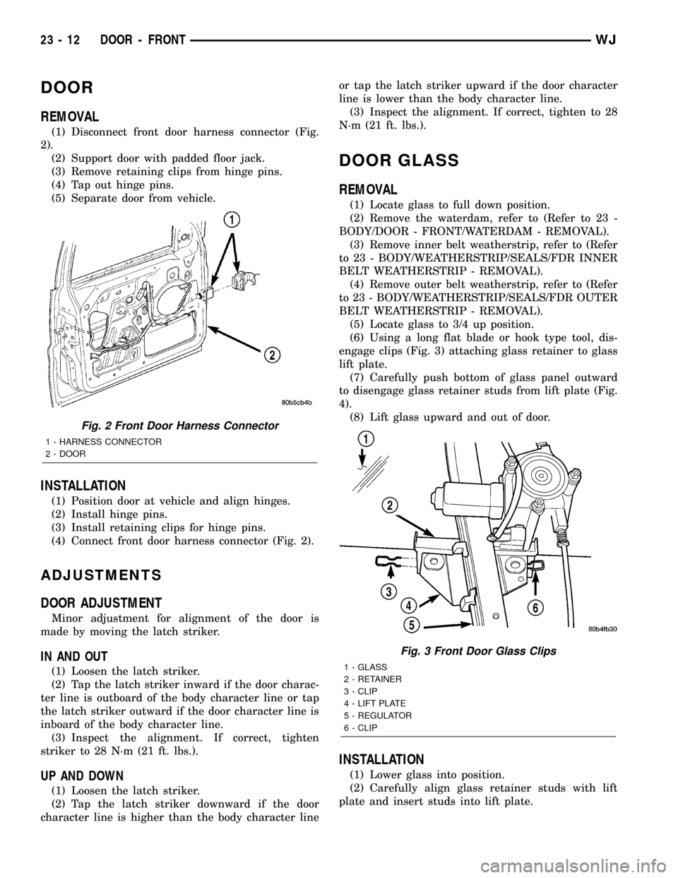
REMOVAL
(1) Disconnect front door harness connector (Fig.
2).
(2) Support door with padded floor jack.
(3) Remove retaining clips from hinge pins.
(4) Tap out hinge pins.
(5) Separate door from vehicle.
INSTALLATION
(1) Position door at vehicle and align hinges.
(2) Install hinge pins.
(3) Install retaining clips for hinge pins.
(4) Connect front door harness connector (Fig. 2).
ADJUSTMENTS
DOOR ADJUSTMENT
Minor adjustment for alignment of the door is
made by moving the latch striker.
IN AND OUT
(1) Loosen the latch striker.
(2) Tap the latch striker inward if the door charac-
ter line is outboard of the body character line or tap
the latch striker outward if the door character line is
inboard of the body character line.
(3) Inspect the alignment. If correct, tighten
striker to 28 N´m (21 ft. lbs.).
UP AND DOWN
(1) Loosen the latch striker.
(2) Tap the latch striker downward if the door
character line is higher than the body character lineor tap the latch striker upward if the door character
line is lower than the body character line.
(3) Inspect the alignment. If correct, tighten to 28
N´m (21 ft. lbs.).
DOOR GLASS
REMOVAL
(1) Locate glass to full down position.
(2) Remove the waterdam, refer to (Refer to 23 -
BODY/DOOR - FRONT/WATERDAM - REMOVAL).
(3) Remove inner belt weatherstrip, refer to (Refer
to 23 - BODY/WEATHERSTRIP/SEALS/FDR INNER
BELT WEATHERSTRIP - REMOVAL).
(4) Remove outer belt weatherstrip, refer to (Refer
to 23 - BODY/WEATHERSTRIP/SEALS/FDR OUTER
BELT WEATHERSTRIP - REMOVAL).
(5) Locate glass to 3/4 up position.
(6) Using a long flat blade or hook type tool, dis-
engage clips (Fig. 3) attaching glass retainer to glass
lift plate.
(7) Carefully push bottom of glass panel outward
to disengage glass retainer studs from lift plate (Fig.
4).
(8) Lift glass upward and out of door.
INSTALLATION
(1) Lower glass into position.
(2) Carefully align glass retainer studs with lift
plate and insert studs into lift plate.
Fig. 2 Front Door Harness Connector
1 - HARNESS CONNECTOR
2 - DOOR
Fig. 3 Front Door Glass Clips
1 - GLASS
2 - RETAINER
3 - CLIP
4 - LIFT PLATE
5 - REGULATOR
6 - CLIP
23 - 12 DOOR - FRONTWJ
Page 1893 of 2199
DOOR
REMOVAL
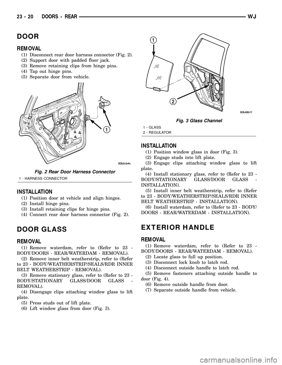
(1) Disconnect rear door harness connector (Fig. 2).
(2) Support door with padded floor jack.
(3) Remove retaining clips from hinge pins.
(4) Tap out hinge pins.
(5) Separate door from vehicle.
INSTALLATION
(1) Position door at vehicle and align hinges.
(2) Install hinge pins.
(3) Install retaining clips for hinge pins.
(4) Connect rear door harness connector (Fig. 2).
DOOR GLASS
REMOVAL
(1) Remove waterdam, refer to (Refer to 23 -
BODY/DOORS - REAR/WATERDAM - REMOVAL).
(2) Remove inner belt weatherstrip, refer to (Refer
to 23 - BODY/WEATHERSTRIP/SEALS/RDR INNER
BELT WEATHERSTRIP - REMOVAL).
(3) Remove stationary glass, refer to (Refer to 23 -
BODY/STATIONARY GLASS/DOOR GLASS -
REMOVAL).
(4) Disengage clips attaching window glass to lift
plate.
(5) Press studs out of lift plate.
(6) Lift window glass from door (Fig. 3).
INSTALLATION
(1) Position window glass in door (Fig. 3).
(2) Engage studs into lift plate.
(3) Engage clips attaching window glass to lift
plate.
(4) Install stationary glass, refer to (Refer to 23 -
BODY/STATIONARY GLASS/DOOR GLASS -
INSTALLATION).
(5) Install inner belt weatherstrip, refer to (Refer
to 23 - BODY/WEATHERSTRIP/SEALS/RDR INNER
BELT WEATHERSTRIP - INSTALLATION).
(6) Install waterdam, refer to (Refer to 23 - BODY/
DOORS - REAR/WATERDAM - INSTALLATION).
EXTERIOR HANDLE
REMOVAL
(1) Remove waterdam, refer to (Refer to 23 -
BODY/DOORS - REAR/WATERDAM - REMOVAL).
(2) Locate glass to full up position.
(3) Disconnect lock knob to latch rod.
(4) Disconnect outside handle to latch rod.
(5) Remove fasteners attaching outside handle to
door (Fig. 4).
(6) Remove outside handle from door.
(7) Separate outside handle from vehicle.
Fig. 2 Rear Door Harness Connector
1 - HARNESS CONNECTOR
Fig. 3 Glass Channel
1 - GLASS
2 - REGULATOR
23 - 20 DOORS - REARWJ