2003 JEEP GRAND CHEROKEE axle seal front
[x] Cancel search: axle seal frontPage 16 of 2199

ENERGY CONSERVING OIL
An Energy Conserving type oil is recommended for
gasoline engines. The designation of ENERGY CON-
SERVING is located on the label of an engine oil con-
tainer.
CONTAINER IDENTIFICATION
Standard engine oil identification notations have
been adopted to aid in the proper selection of engine
oil. The identifying notations are located on the label
of engine oil plastic bottles and the top of engine oil
cans (Fig. 6).
DESCRIPTION
A multi-purpose, hypoid gear lubricant which con-
forms to MIL-L-2105C and API GL 5 quality specifi-
cations should be used. Mopar Hypoid Gear
Lubricant conforms to these specifications.
FRONT AXLE
²Lubricant is SAE 75W-140 SYNTHETIC.
REAR AXLE
²Lubricant is a thermally stable SAE 80W-90
gear lubricant.
²Lubricant for heavy-duty or trailer tow use is
SAE 75W-140 SYNTHETIC.
NOTE: Trac-lokTand Vari-lokTequipped axles
require a friction modifier be added to the lubricant.
DESCRIPTION - TRANSFER CASE - NV242
Recommended lubricant for the NV242 transfer
case is MopartATF+4, type 9602 Automatic Trans-
mission Fluid.
DESCRIPTION - TRANSFER CASE - NV247
MopartTransfer Case Lubricant (P/N 05016796) is
the only lubricant recommended for the NV247
transfer case.
DESCRIPTION - AUTOMATIC TRANSMISSION
FLUID
NOTE: Refer to Service Procedures in this group for
fluid level checking procedures.
MopartATF +4, type 9602, Automatic Transmis-
sion Fluid is the recommended fluid for
DaimlerChrysler automatic transmissions.
Dexron II fluid IS NOT recommended. Clutch
chatter can result from the use of improper
fluid.
MopartATF +4, type 9602, Automatic Transmis-
sion Fluid when new is red in color. The ATF is dyed
red so it can be identified from other fluids used in
the vehicle such as engine oil or antifreeze. The red
color is not permanent and is not an indicator of fluid
condition. As the vehicle is driven, the ATF will begin
to look darker in color and may eventually become
brown.This is normal.ATF+4 also has a unique
odor that may change with age. Consequently, odor
and color cannot be used to indicate the fluid condi-
tion or the need for a fluid change.
FLUID ADDITIVES
DaimlerChrysler strongly recommends against the
addition of any fluids to the transmission, other than
those automatic transmission fluids listed above.
Exceptions to this policy are the use of special dyes
to aid in detecting fluid leaks.
Various ªspecialº additives and supplements exist
that claim to improve shift feel and/or quality. These
additives and others also claim to improve converter
clutch operation and inhibit overheating, oxidation,
varnish, and sludge. These claims have not been sup-
ported to the satisfaction of DaimlerChrysler and
these additivesmust not be used.The use of trans-
mission ªsealersº should also be avoided, since they
may adversely affect the integrity of transmission
seals.
Fig. 5 Temperature/Engine Oil Viscosity - 4.0L
Fig. 6 API Symbol
WJLUBRICATION & MAINTENANCE 0 - 5
FLUID TYPES (Continued)
Page 60 of 2199
FRONT AXLE - 186FBI
TABLE OF CONTENTS
page page
FRONT AXLE - 186FBI
DESCRIPTION.........................15
OPERATION...........................15
DIAGNOSIS AND TESTING................16
REMOVAL.............................20
INSTALLATION.........................21
ADJUSTMENTS........................21
SPECIFICATIONS.......................30
SPECIAL TOOLS.......................31
AXLE SHAFTS
REMOVAL.............................34
INSTALLATION.........................34
AXLE SHAFT SEALS
REMOVAL.............................35
INSTALLATION.........................35
AXLE - C/V JOINT
REMOVAL.............................35
INSTALLATION.........................35
AXLE - U-JOINT
REMOVAL.............................36INSTALLATION.........................37
PINION SEAL
REMOVAL.............................37
INSTALLATION.........................37
COLLAPSIBLE SPACER
REMOVAL.............................39
INSTALLATION.........................39
DIFFERENTIAL
REMOVAL.............................40
DISASSEMBLY.........................42
ASSEMBLY............................42
INSTALLATION.........................43
DIFFERENTIAL CASE BEARINGS
REMOVAL.............................44
INSTALLATION.........................44
PINION GEAR/RING GEAR
REMOVAL.............................45
INSTALLATION.........................46
FRONT AXLE - 186FBI
DESCRIPTION
The Front Beam-design Iron (FBI) axle consists of
a cast iron differential housing with axle shaft tubes
extending from either side. The tubes are pressed
into the differential housing and welded. The axles
are semi-floating axle shafts, meaning the loads are
supported by the hub bearings. The axle shafts are
retained by nuts at the hub bearings.
The differential case is a one-piece design. Differ-
ential bearing preload and ring gear backlash is
adjusted by the use of shims located between the dif-
ferential bearing cups and housing. Pinion bearing
preload is set and maintained by the use of a collaps-
ible spacer. A differential cover provides a means for
inspection and servicing.
An optional Vari-Loktdifferential has a one-piece
differential case which contains the gerotor pump
assembly and the clutch mechinism. This unit is ser-
viced as an assembly.
OPERATION
The axle receives power from the transfer case
through the front propeller shaft. The front propeller
shaft is connected to the pinion gear which rotatesthe differential through the gear mesh with the ring
gear bolted to the differential case. The engine power
is transmitted to the axle shafts through the pinion
mate and side gears. The side gears are splined to
the axle shafts.
STANDARD DIFFERENTIAL
During straight-ahead driving, the differential pinion
gears do not rotate on the pinion mate shaft. This
occurs because input torque applied to the gears is
divided and distributed equally between the two side
gears. As a result, the pinion gears revolve with the pin-
ion mate shaft but do not rotate around it (Fig. 1).
When turning corners, the outside wheel must
travel a greater distance than the inside wheel to
complete a turn. The difference must be compensated
for to prevent the tires from scuffing and skidding
through turns. To accomplish this, the differential
allows the axle shafts to turn at unequal speeds (Fig.
2). In this instance, the input torque applied to the
pinion gears is not divided equally. The pinion gears
now rotate around the pinion mate shaft in opposite
directions. This allows the side gear and axle shaft
attached to the outside wheel to rotate at a faster
speed.
WJFRONT AXLE - 186FBI 3 - 15
Page 64 of 2199

Condition Possible Causes Correction
Differential Gears Scored 1. Insufficient lubrication. 1. Replace scored gears. Fill
differential with the correct fluid type
and quantity.
2. Improper grade of lubricant. 2. Replace scored gears. Fill
differential with the correct fluid type
and quantity.
3. Excessive spinning of one
wheel/tire.3. Replace scored gears. Inspect all
gears, pinion bores, and shaft for
damage. Service as necessary.
Loss Of Lubricant 1. Lubricant level too high. 1. Drain lubricant to the correct
level.
2. Worn axle shaft seals. 2. Replace seals.
3. Cracked differential housing. 3. Repair as necessary.
4. Worn pinion seal. 4. Replace seal.
5. Worn/scored yoke. 5. Replace yoke and seal.
6. Axle cover not properly sealed. 6. Remove, clean, and re-seal
cover.
Axle Overheating 1. Lubricant level low. 1. Fill differential to correct level.
2. Improper grade of lubricant. 2. Fill differential with the correct
fluid type and quantity.
3. Bearing pre-loads too high. 3. Re-adjust bearing pre-loads.
4. Insufficient ring gear backlash. 4. Re-adjust ring gear backlash.
Gear Teeth Broke 1. Overloading. 1. Replace gears. Examine other
gears and bearings for possible
damage.
2. Erratic clutch operation. 2. Replace gears and examine the
remaining parts for damage. Avoid
erratic clutch operation.
3. Ice-spotted pavement. 3. Replace gears and examine
remaining parts for damage.
4. Improper adjustments. 4. Replace gears and examine
remaining parts for damage. Ensure
ring gear backlash is correct.
WJFRONT AXLE - 186FBI 3 - 19
FRONT AXLE - 186FBI (Continued)
Page 77 of 2199
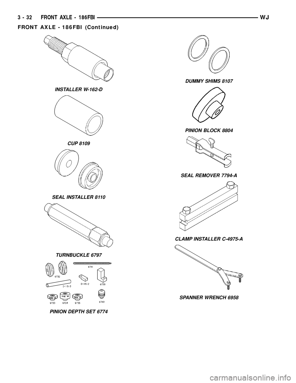
INSTALLER W-162-D
CUP 8109
SEAL INSTALLER 8110
TURNBUCKLE 6797
PINION DEPTH SET 6774
DUMMY SHIMS 8107
PINION BLOCK 8804
SEAL REMOVER 7794-A
CLAMP INSTALLER C-4975-A
SPANNER WRENCH 6958
3 - 32 FRONT AXLE - 186FBIWJ
FRONT AXLE - 186FBI (Continued)
Page 79 of 2199
AXLE SHAFTS
REMOVAL
If the axle shaft and hub bearing are being
removed in order to service another component, the
axle shaft and hub bearing can be removed as an
assembly.
(1) Raise and support the vehicle.
(2) Remove the wheel and tire assembly.
(3) Remove brake caliper, rotor and ABS wheel
speed sensor.
(4) Remove cotter pin, nut retainer and axle nut.
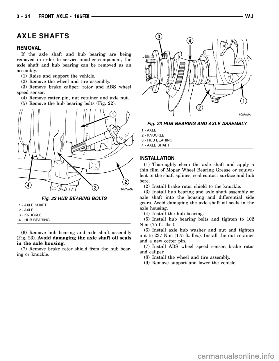
(5) Remove the hub bearing bolts (Fig. 22).
(6) Remove hub bearing and axle shaft assembly
(Fig. 23).Avoid damaging the axle shaft oil seals
in the axle housing.
(7) Remove brake rotor shield from the hub bear-
ing or knuckle.
INSTALLATION
(1) Thoroughly clean the axle shaft and apply a
thin film of Mopar Wheel Bearing Grease or equiva-
lent to the shaft splines, seal contact surface and hub
bore.
(2) Install brake rotor shield to the knuckle.
(3) Install hub bearing and axle shaft assembly or
axle shaft into the housing and differential side
gears. Avoid damaging the axle shaft oil seals in the
axle housing.
(4) Install the hub bearing.
(5) Install hub bearing bolts and tighten to 102
N´m (75 ft. lbs.).
(6) Install axle hub washer and nut and tighten
nut to 237 N´m (175 ft. lbs.). Install the nut retainer
and a new cotter pin.
(7) Install ABS wheel speed sensor, brake rotor
and caliper.
(8) Install the wheel and tire assembly.
(9) Remove support and lower the vehicle.
Fig. 22 HUB BEARING BOLTS
1 - AXLE SHAFT
2 - AXLE
3 - KNUCKLE
4 - HUB BEARING
Fig. 23 HUB BEARING AND AXLE ASSEMBLY
1 - AXLE
2 - KNUCKLE
3 - HUB BEARING
4 - AXLE SHAFT
3 - 34 FRONT AXLE - 186FBIWJ
Page 80 of 2199
AXLE SHAFT SEALS
REMOVAL
(1) Raise and support vehicle.
(2) Remove axle shafts.
(3) Remove differential assembly.
(4) Remove inner axle shaft seals with a pry bay.
INSTALLATION
(1) Remove any sealer remaining from original
seals.
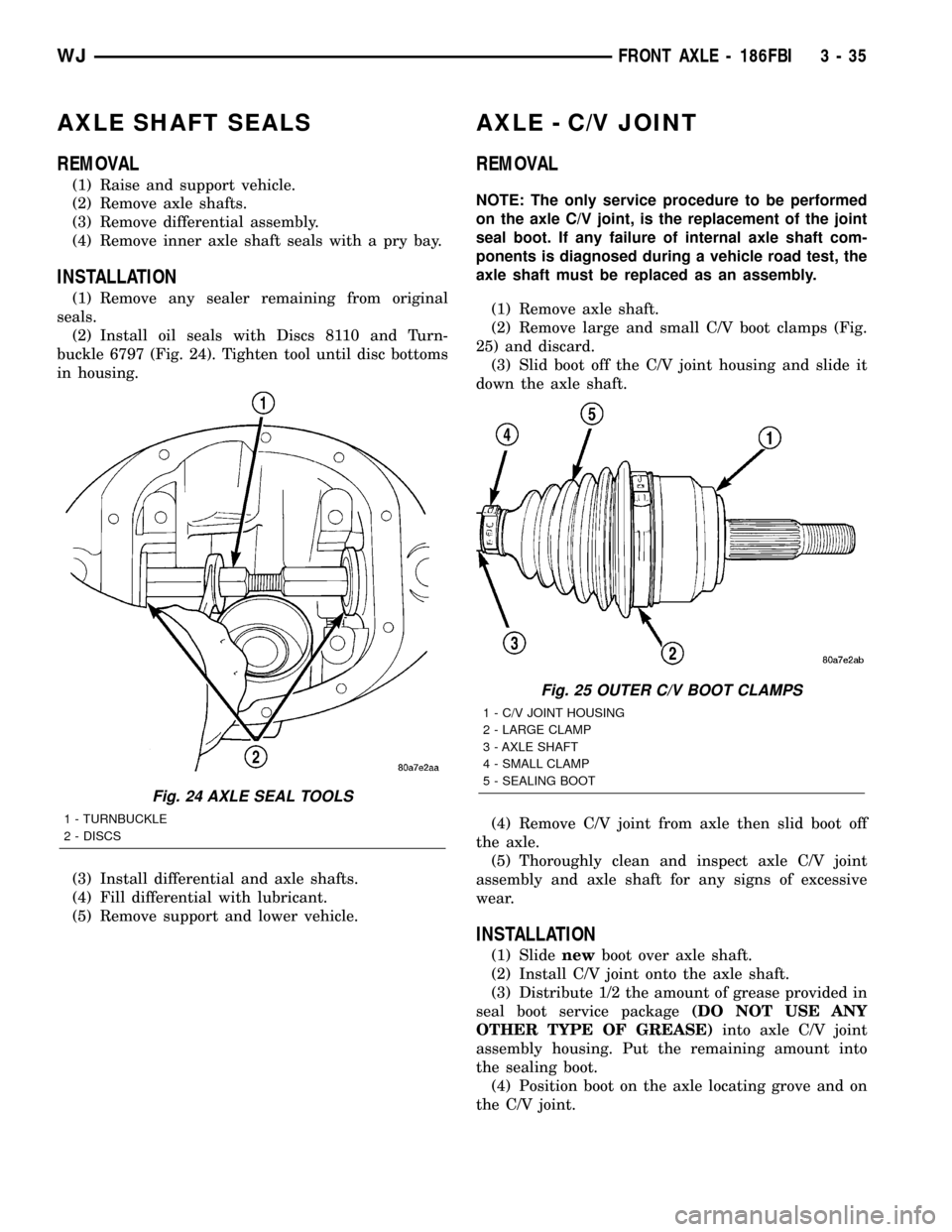
(2) Install oil seals with Discs 8110 and Turn-
buckle 6797 (Fig. 24). Tighten tool until disc bottoms
in housing.
(3) Install differential and axle shafts.
(4) Fill differential with lubricant.
(5) Remove support and lower vehicle.
AXLE - C/V JOINT
REMOVAL
NOTE: The only service procedure to be performed
on the axle C/V joint, is the replacement of the joint
seal boot. If any failure of internal axle shaft com-
ponents is diagnosed during a vehicle road test, the
axle shaft must be replaced as an assembly.
(1) Remove axle shaft.
(2) Remove large and small C/V boot clamps (Fig.
25) and discard.
(3) Slid boot off the C/V joint housing and slide it
down the axle shaft.
(4) Remove C/V joint from axle then slid boot off
the axle.
(5) Thoroughly clean and inspect axle C/V joint
assembly and axle shaft for any signs of excessive
wear.
INSTALLATION
(1) Slidenewboot over axle shaft.
(2) Install C/V joint onto the axle shaft.
(3) Distribute 1/2 the amount of grease provided in
seal boot service package(DO NOT USE ANY
OTHER TYPE OF GREASE)into axle C/V joint
assembly housing. Put the remaining amount into
the sealing boot.
(4) Position boot on the axle locating grove and on
the C/V joint.
Fig. 24 AXLE SEAL TOOLS
1 - TURNBUCKLE
2 - DISCS
Fig. 25 OUTER C/V BOOT CLAMPS
1 - C/V JOINT HOUSING
2 - LARGE CLAMP
3 - AXLE SHAFT
4 - SMALL CLAMP
5 - SEALING BOOT
WJFRONT AXLE - 186FBI 3 - 35
Page 81 of 2199
CAUTION: Boot must not be dimpled, stretched or
out of shape in any way. If not shaped correctly,
equalize pressure in boot and shape it by hand.
(5) Install the two boot clamps.
(6) Crimp the boot clamps with Clamp Installer
C-4975A. Place clamp tool over bridge of clamp (Fig.
26).
(7) Tighten nut on the tool until jaws on tool are
closed completely together (Fig. 27) and (Fig. 28).
(8) Install the axle shaft.
AXLE - U-JOINT
REMOVAL
CAUTION: Clamp only the narrow forged portion of
the yoke in the vise. Do not over tighten the vise
jaws, to avoid distorting the yoke.
(1) Remove axle shaft.
(2) Remove the bearing cap retaining snap rings
(Fig. 29).
NOTE: Saturate the bearing caps with penetrating
oil prior to removal.
(3) Locate a socket with an inside diameter is
larger than the bearing cap. Place the socket (receiv-
er) against the yoke and around the perimeter of the
bearing cap to be removed.
(4) Locate a socket with an outside diameter is
smaller than the bearing cap. Place the socket (driv-
er) against the opposite bearing cap.
(5) Position the yoke with the sockets in a vise
(Fig. 30).
(6) Tighten the vise jaws to force the bearing cap
into the larger socket (receiver).
(7) Release the vise jaws. Remove the sockets and
bearing cap that was partially forced out of the yoke.
(8) Repeat the above procedure for the remaining
bearing cap and remove spider from the propeller
shaft yoke.
Fig. 26 CRIMPING TOOL
1 - INSTALLER
2 - AXLE SHAFT
3 - CLAMP
4 - SEALING BOOT
Fig. 27 SMALL BOOT CLAMP
1 - CLAMP
2 - INSTALLER
3 - AXLE SHAFT
4 - SEALING BOOT
Fig. 28 LARGE BOOT CLAMP
1 - CLAMP TOOL
2 - SEALING BOOT
3 - OUTER C/V JOINT
4 - BOOT CLAMP
3 - 36 FRONT AXLE - 186FBIWJ
AXLE - C/V JOINT (Continued)
Page 82 of 2199

INSTALLATION
(1) Pack the bearing caps 1/3 full of wheel bearing
lubricant. Apply extreme pressure (EP), lithium-base
lubricant to aid in installation.
(2) Position the spider in the yoke. Insert the seals
and bearings, then tap bearing caps into the yoke
bores far enough to hold the spider in position.
(3) Place the socket (driver) against one bearing
cap. Position the yoke with the socket in a vise.
(4) Tighten the vise to force the bearing caps into
the yoke. Force the caps enough to install the retain-
ing clips.
(5) Install the bearing cap retaining clips.
(6) Install axle shaft.
PINION SEAL
REMOVAL
(1) Raise and support the vehicle.
(2) Remove wheel and tire assemblies.
(3) Remove brake rotors and calipers, refer to 5
Brakes for procedures.
(4) Mark propeller shaft and pinion companion
flange for installation reference.
(5) Remove the propeller shaft from the pinion
companion flange.
(6) Rotate the pinion gear a minimum of ten times
and verify the pinion rotates smoothly.
(7) Record torque necessary to rotate the pinion
gear with a inch pound torque wrench.
(8) Using a short piece of pipe and Spanner
Wrench 6958 to hold the pinion companion flange
and remove the pinion nut and washer.
(9) Remove pinion companion flange with Remover
C-452 and Flange Wrench C-3281.
(10) Remove pinion seal with Remover 7794-A and
a slide hammer (Fig. 31).
INSTALLATION
(1) Apply a light coating of gear lubricant on the
lip of pinion seal. Install seal with an appropriate
installer (Fig. 32).
(2) Install pinion companion flange on the pinion
gear with Installer W-162-D, Cup 8109 and Wrench
6958.
CAUTION: Never exceed the minimum tightening
torque 298 N´m (220 ft. lbs.) while installing pinion
nut at this point. Damage to collapsible spacer or
bearings may result.
(3) Install the pinion washer and anewnut on
the pinion gear.Tighten the nut only enough to
remove the shaft end play.
Fig. 29 AXLE SHAFT OUTER U-JOINT
1 - SHAFT YOKE
2 - BEARING CAP
3 - SNAP RINGS
4 - BEARING CAP
5 - SPINDLE YOKE
6 - BEARING
7 - BEARING CAP
8 - SNAP RINGS
9 - BEARING CAP
Fig. 30 YOKE BEARING CAP
1 - LARGE-DIAMETER SOCKET
2 - VISE
3 - SMALL-DIAMETER SOCKET
WJFRONT AXLE - 186FBI 3 - 37
AXLE - U-JOINT (Continued)