2003 JEEP GRAND CHEROKEE compress
[x] Cancel search: compressPage 42 of 2199

STABILIZER BAR
DESCRIPTION
The stabilizer bar extends across the back side of
the rear axle. Links are connected between the bar
and frame rail brackets. The stabilizer bar and links
are isolated by rubber bushings.
OPERATION
The stabilizer bar is used to control vehicle body
roll, during turns. The bar helps control the vehicle
body in relationship to the suspension.
REMOVAL
(1) Raise and support the vehicle.
(2) Remove the stabilizer bar links from stabilizer
bar and frame mount. (Fig. 7).
(3) Remove the stabilizer bar retainer bolts.
(4) Remove the stabilizer bar.
INSTALLATION
(1) Position the stabilizer bar on the axle and
install the retainers and bolts. Ensure the bar is cen-
tered with equal spacing on both sides. Tighten the
bolts to 54 N´m (40 ft. lbs.).
(2) Install the links to the stabilizer bar and frame
brackets.
(3) Tighten the nuts at the stabilizer bar to 54
N´m (40 ft. lbs.).
(4) Tighten the nuts at the frame brackets to 92
N´m (68 ft. lbs.).
(5) Remove support and lower the vehicle.
UPPER BALL JOINT
DESCRIPTION - UPPER SUSPENSION ARM,
BUSHINGS, AND BALL JOINT
The suspension arm uses vertical spool bushings to
isolate road noise. The suspension arm is bolted
through bushings to cage nuts in the body and a ball
joint plate to the top of the differential housing.
OPERATION - UPPER SUSPENSION ARM,
BUSHINGS, AND BALL JOINT
The upper suspension arm provides fore/aft and
lateral location of the rear axle. The suspension arm
travel is limited through the use of jounce bumpers
in compression and shock absorbers in rebound.
REMOVAL
(1) Raise and support the vehicle.
(2) Support the rear axle with a hydraulic jack.
(3) Remove the ball joint nut from the top of the
upper suspension arm (Fig. 8).
(4) Separate ball joint from the arm with Remover
8278 (Fig. 9).
NOTE: It may be necessary to strike the upper con-
trol arm with a hammer to separate the ball joint
from the arm.
(5) Remove the ball joint mounting bolts (Fig.
10)from the differential housing.
(6) Remove the ball joint from the differential
housing.
Fig. 6 Isolator Spring Locator - Typical
1 - LOWER ISOLATOR
2 - SPRING LOCATOR
3 - COIL SPRING
Fig. 7 Rear Stabilizer Bar
1 - LINK
2 - RETAINER
3 - BUSHING
4 - STABILIZER BAR
WJREAR 2 - 21
SPRING (Continued)
Page 43 of 2199

INSTALLATION
(1) Install the ball joint on the differential hous-
ing.
(2) Install the ball joint mounting bolts and
tighten to 136 N´m (100 ft. lbs.).
(3) Raise the rear axle with a hydraulic jack to
align the upper arm with the ball joint.(4) Pull the arm down on the ball joint stud and
install anewnut. Tighten the nut to 142 N´m (105
ft. lbs.).
(5) Remove the supports and lower the vehicle.
UPPER CONTROL ARM
DESCRIPTION
The suspension arm uses vertical spool bushings to
isolate road noise. The suspension arm is bolted
through bushings to cage nuts in the body and a ball
joint plate to the top of the differential housing.
OPERATION
The upper suspension arm provides fore/aft and
lateral location of the rear axle. The suspension arm
travel is limited through the use of jounce bumpers
in compression and shock absorbers in rebound.
REMOVAL
(1) Raise and support the vehicle.
(2) Support the rear axle with a hydraulic jack.
(3) Remove the park brake cables and brake hose
from the arm (Fig. 11).
(4) Remove the ball joint nut from the top of the
upper suspension arm (Fig. 12).
(5) Separate ball joint from the arm with Remover
8278 (Fig. 13).
Fig. 8 Ball Joint Nut
1 - BALL JOINT NUT
2 - UPPER SUSPENSION ARM
Fig. 9 Separate Ball Joint
1 - REMOVER
2 - UPPER SUSPENSION ARM
3 - BALL JOINT STUD
Fig. 10 Ball Joint Mounting Bolts
1 - BALL JOINT
2 - MOUNTING BOLTS
2 - 22 REARWJ
UPPER BALL JOINT (Continued)
Page 71 of 2199

(10) Push and hold differential case to pinion gear
side of the housing and zero dial indicator (Fig. 15).
(11) Push and hold differential case to ring gear
side of the housing and record dial indicator reading
(Fig. 16).(12) Add 0.152 mm (0.006 in.) to the zero end play
total. This new total represents the thickness of
shims to compress or preload the new bearings when
the differential is installed.
(13) Rotate dial indicator out of the way on the
pilot stud.
(14) Remove differential case and dummy bearings
from the housing.
(15) Install the pinion gear in the housing. Install
the pinion yoke and establish the correct pinion
rotating torque.
(16) Install differential case and Dummy Bearings
D-348 in the housing.
(17) Install a single dummy shim in the ring gear
side. Install bearing caps and tighten bolts snug.
(18) Seat ring gear side dummy bearing (Fig. 13).
(19) Position the dial indicator plunger on a flat
surface between the ring gear bolt heads (Fig. 14).
(20) Push and hold differential case toward pinion
gear and zero dial indicator (Fig. 17).
Fig. 15 ZERO DIAL INDICATOR
1 - FORCE DIFFERENTIAL CASE TO PINION GEAR SIDE
2 - PILOT STUD
3 - INDICATOR EXTENSION
4 - DIAL INDICATOR FACE
Fig. 16 RECORED DIAL INDICATOR READING
1 - DIAL INDICATOR
2 - DIFFERENTIAL CASE TO RING GEAR SIDE
3 - DIFFERENTIAL HOUSING
Fig. 17 ZERO DIAL INDICATOR
1 - DIAL INDICATOR
2 - FORCE DIFFERENTIAL CASE TO PINION GEAR SIDE
3 - PINION GEAR
4 - DIFFERENTIAL HOUSING
5 - DIFFERENTIAL CASE
3 - 26 FRONT AXLE - 186FBIWJ
FRONT AXLE - 186FBI (Continued)
Page 106 of 2199

(8) Thread Pilot Stud C-3288-B into rear cover bolt
hole below ring gear (Fig. 17).
(9) Attach a Dial Indicator C-3339 to pilot stud.
Position the dial indicator plunger on a flat surface
between the ring gear bolt heads (Fig. 17).
(10) Push and hold differential case to pinion gear
side of the housing and zero dial indicator (Fig. 18).
(11) Push and hold differential case to ring gear
side of the housing and record dial indicator reading
(Fig. 19).
(12) Add 0.152 mm (0.006 in.) to the zero end play
total. This new total represents the thickness of
shims to compress, or preload the new bearings when
the differential is installed.
(13) Rotate dial indicator out of the way on the
pilot stud.
(14) Remove differential case and dummy bearings
from the housing.
(15) Install the pinion gear in axle housing. Install
the pinion yoke and establish the correct pinion
rotating torque.
(16) Install differential case and Dummy Bearings
D-348 in the housing.
(17) Install a single dummy shim in the ring gear
side. Install bearing caps and tighten bolts snug.
(18) Seat ring gear side dummy bearing (Fig. 16).
(19) Position the dial indicator plunger on a flat
surface between the ring gear bolt heads. (Fig. 17).(20) Push and hold differential case toward pinion
gear and zero dial indicator (Fig. 20).
(21) Push and hold differential case to ring gear
side of the housing and record dial indicator reading
(Fig. 21). Add dummy shim thickness to this reading.
This will be the total shim thickness to achieve zero
backlash.
(22) Subtract 0.076 mm (0.003 in.) from the dial
indicator reading to compensate for backlash between
ring and pinion gears. This total is the thickness
shim required to achieve proper backlash.
(23) Subtract the backlash shim thickness from
the total preload shim thickness. The remainder is
Fig. 17 DIFFERENTIAL SIDE PLAY
1 - DIFFERENTIAL CASE
2 - DIFFERENTIAL HOUSING
3 - PILOT STUD
4 - DIAL INDICATOR
Fig. 18 ZERO DIAL INDICATOR
1 - FORCE DIFFERENTIAL CASE TO PINION GEAR SIDE
2 - PILOT STUD
3 - DIAL INDICATOR
4 - ZERO DIAL INDICATOR FACE
Fig. 19 DIFFERENTIAL TO RING GEAR SIDE
1 - DIAL INDICATOR
2 - FORCE DIFFERENTIAL CASE TO RING GEAR SIDE
3 - DIFFERENTIAL HOUSING
WJREAR AXLE - 198RBI 3 - 61
REAR AXLE - 198RBI (Continued)
Page 125 of 2199

(2) Remove ring gear if the ring gear is to be
replaced. The Trac-loktdifferential can be serviced
with the ring gear installed.
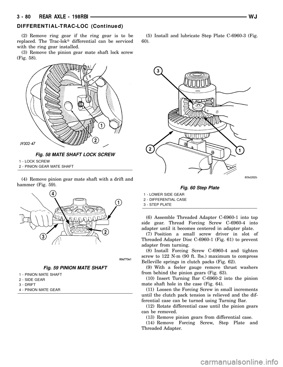
(3) Remove the pinion gear mate shaft lock screw
(Fig. 58).
(4) Remove pinion gear mate shaft with a drift and
hammer (Fig. 59).(5) Install and lubricate Step Plate C-6960-3 (Fig.
60).
(6) Assemble Threaded Adapter C-6960-1 into top
side gear. Thread Forcing Screw C-6960-4 into
adapter until it becomes centered in adapter plate.
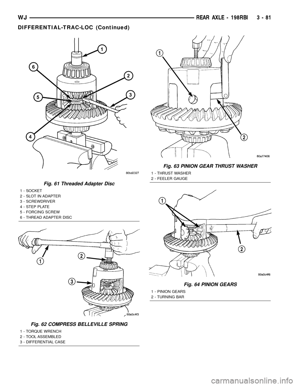
(7) Position a small screw driver in slot of
Threaded Adapter Disc C-6960-1 (Fig. 61) to prevent
adapter from turning.
(8) Install Forcing Screw C-6960-4 and tighten
screw to 122 N´m (90 ft. lbs.) maximum to compress
Belleville springs in clutch packs (Fig. 62).
(9) With a feeler gauge remove thrust washers
from behind the pinion gears (Fig. 63).
(10) Insert Turning Bar C-6960-2 into the pinion
mate shaft hole in the case (Fig. 64).
(11) Loosen the Forcing Screw in small increments
until the clutch pack tension is relieved and the dif-
ferential case can be turned using Turning Bar.
(12) Rotate differential case until the pinion gears
can be removed.
(13) Remove pinion gears from differential case.
(14) Remove Forcing Screw, Step Plate and
Threaded Adapter.
Fig. 58 MATE SHAFT LOCK SCREW
1 - LOCK SCREW
2 - PINION GEAR MATE SHAFT
Fig. 59 PINION MATE SHAFT
1 - PINION MATE SHAFT
2 - SIDE GEAR
3 - DRIFT
4 - PINION MATE GEAR
Fig. 60 Step Plate
1 - LOWER SIDE GEAR
2 - DIFFERENTIAL CASE
3 - STEP PLATE
3 - 80 REAR AXLE - 198RBIWJ
DIFFERENTIAL-TRAC-LOC (Continued)
Page 126 of 2199

Fig. 61 Threaded Adapter Disc
1 - SOCKET
2 - SLOT IN ADAPTER
3 - SCREWDRIVER
4 - STEP PLATE
5 - FORCING SCREW
6 - THREAD ADAPTER DISC
Fig. 62 COMPRESS BELLEVILLE SPRING
1 - TORQUE WRENCH
2 - TOOL ASSEMBLED
3 - DIFFERENTIAL CASE
Fig. 63 PINION GEAR THRUST WASHER
1 - THRUST WASHER
2 - FEELER GAUGE
Fig. 64 PINION GEARS
1 - PINION GEARS
2 - TURNING BAR
WJREAR AXLE - 198RBI 3 - 81
DIFFERENTIAL-TRAC-LOC (Continued)
Page 127 of 2199

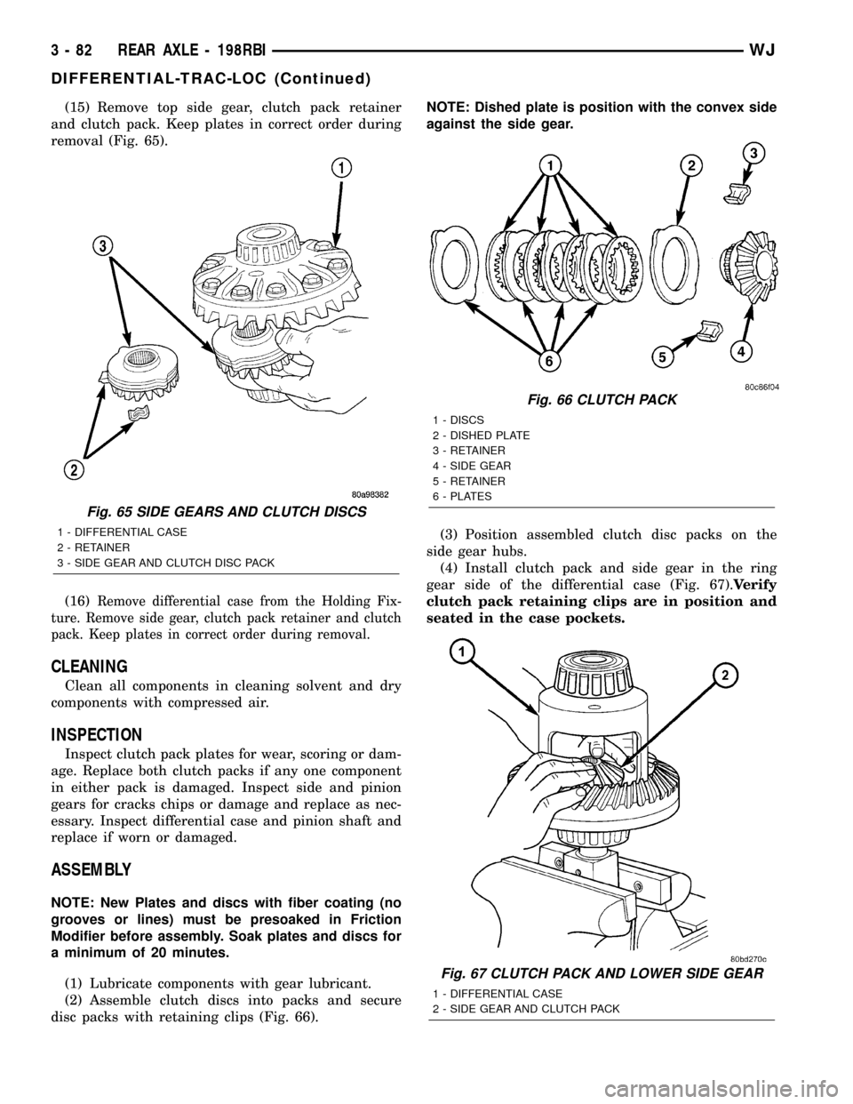
(15) Remove top side gear, clutch pack retainer
and clutch pack. Keep plates in correct order during
removal (Fig. 65).
(16)
Remove differential case from the Holding Fix-
ture. Remove side gear, clutch pack retainer and clutch
pack. Keep plates in correct order during removal.
CLEANING
Clean all components in cleaning solvent and dry
components with compressed air.
INSPECTION
Inspect clutch pack plates for wear, scoring or dam-
age. Replace both clutch packs if any one component
in either pack is damaged. Inspect side and pinion
gears for cracks chips or damage and replace as nec-
essary. Inspect differential case and pinion shaft and
replace if worn or damaged.
ASSEMBLY
NOTE: New Plates and discs with fiber coating (no
grooves or lines) must be presoaked in Friction
Modifier before assembly. Soak plates and discs for
a minimum of 20 minutes.
(1) Lubricate components with gear lubricant.
(2) Assemble clutch discs into packs and secure
disc packs with retaining clips (Fig. 66).NOTE: Dished plate is position with the convex side
against the side gear.
(3) Position assembled clutch disc packs on the
side gear hubs.
(4) Install clutch pack and side gear in the ring
gear side of the differential case (Fig. 67).Verify
clutch pack retaining clips are in position and
seated in the case pockets.
Fig. 65 SIDE GEARS AND CLUTCH DISCS
1 - DIFFERENTIAL CASE
2 - RETAINER
3 - SIDE GEAR AND CLUTCH DISC PACK
Fig. 66 CLUTCH PACK
1 - DISCS
2 - DISHED PLATE
3 - RETAINER
4 - SIDE GEAR
5 - RETAINER
6 - PLATES
Fig. 67 CLUTCH PACK AND LOWER SIDE GEAR
1 - DIFFERENTIAL CASE
2 - SIDE GEAR AND CLUTCH PACK
3 - 82 REAR AXLE - 198RBIWJ
DIFFERENTIAL-TRAC-LOC (Continued)
Page 128 of 2199

(5) Position the differential case on the Holding
Fixture 6965.
(6) Install lubricated Step Plate C-6960-3 in lower
side gear (Fig. 68).
(7) Install the upper side gear and clutch disc pack
(Fig. 68).
(8) Hold assembly in position. Insert Threaded
Adapter C-6960-1 into top side gear.
(9) Install Forcing Screw C-6960-4 and tighten
screw to slightly compress clutch disc.
(10) Place pinion gears in position in side gears
and verify that the pinion mate shaft hole is aligned.
(11) Rotate case with Turning Bar C-6960-2 until
the pinion mate shaft holes in pinion gears align
with holes in case. It may be necessary to slightly
tighten the forcing screw in order to install the pin-
ion gears.
(12) Tighten forcing screw to 122 N´m (90 ft. lbs.)
maximum to compress the Belleville springs.
(13) Lubricate and install thrust washers behind
pinion gears and align washers with a small screw
driver. Insert mate shaft into each pinion gear to ver-
ify alignment.
(14) Remove Forcing Screw, Step Plate and
Threaded Adapter.(15) Install pinion gear mate shaft and align holes
in shaft and case.
(16) Install pinion mate shaft lock screw finger
tight to hold shaft during differential installation.
(17) Lubricate all differential components with
hypoid gear lubricant.
DIFFERENTIAL CASE
BEARINGS
REMOVAL
(1) Raise and support vehicle.
(2) Remove differential case from axle housing.
(3) Remove bearings from the differential case
with Puller/Press C-293-PA, Adapter 8352 and Plug
SP-3289 (Fig. 69).
Fig. 68 CLUTCH PACK AND UPPER SIDE GEAR
1 - SIDE GEAR AND CLUTCH PACK
2 - DIFFERENTIAL CASE
3 - STEP PLATE
Fig. 69 Differential Bearing
1 - ADAPTERS
2 - BEARING
3 - DIFFERENTIAL
4 - PLUG
5 - PULLER
WJREAR AXLE - 198RBI 3 - 83
DIFFERENTIAL-TRAC-LOC (Continued)