2003 JEEP GRAND CHEROKEE compress
[x] Cancel search: compressPage 2166 of 2199

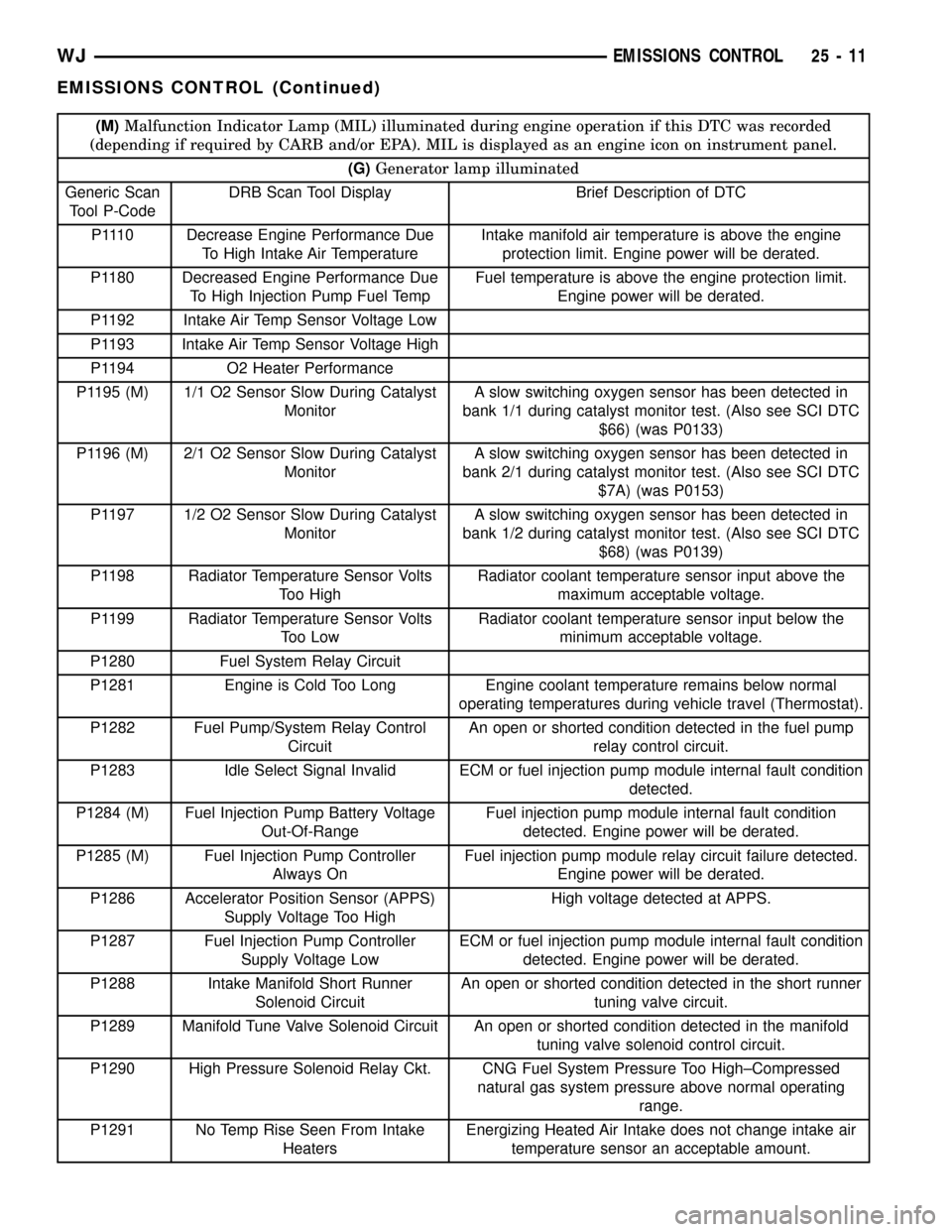
(M)Malfunction Indicator Lamp (MIL) illuminated during engine operation if this DTC was recorded
(depending if required by CARB and/or EPA). MIL is displayed as an engine icon on instrument panel.
(G)Generator lamp illuminated
Generic Scan
Tool P-CodeDRB Scan Tool Display Brief Description of DTC
P1110 Decrease Engine Performance Due
To High Intake Air TemperatureIntake manifold air temperature is above the engine
protection limit. Engine power will be derated.
P1180 Decreased Engine Performance Due
To High Injection Pump Fuel TempFuel temperature is above the engine protection limit.
Engine power will be derated.
P1192 Intake Air Temp Sensor Voltage Low
P1193 Intake Air Temp Sensor Voltage High
P1194 O2 Heater Performance
P1195 (M) 1/1 O2 Sensor Slow During Catalyst
MonitorA slow switching oxygen sensor has been detected in
bank 1/1 during catalyst monitor test. (Also see SCI DTC
$66) (was P0133)
P1196 (M) 2/1 O2 Sensor Slow During Catalyst
MonitorA slow switching oxygen sensor has been detected in
bank 2/1 during catalyst monitor test. (Also see SCI DTC
$7A) (was P0153)
P1197 1/2 O2 Sensor Slow During Catalyst
MonitorA slow switching oxygen sensor has been detected in
bank 1/2 during catalyst monitor test. (Also see SCI DTC
$68) (was P0139)
P1198 Radiator Temperature Sensor Volts
Too HighRadiator coolant temperature sensor input above the
maximum acceptable voltage.
P1199 Radiator Temperature Sensor Volts
Too LowRadiator coolant temperature sensor input below the
minimum acceptable voltage.
P1280 Fuel System Relay Circuit
P1281 Engine is Cold Too Long Engine coolant temperature remains below normal
operating temperatures during vehicle travel (Thermostat).
P1282 Fuel Pump/System Relay Control
CircuitAn open or shorted condition detected in the fuel pump
relay control circuit.
P1283 Idle Select Signal Invalid ECM or fuel injection pump module internal fault condition
detected.
P1284 (M) Fuel Injection Pump Battery Voltage
Out-Of-RangeFuel injection pump module internal fault condition
detected. Engine power will be derated.
P1285 (M) Fuel Injection Pump Controller
Always OnFuel injection pump module relay circuit failure detected.
Engine power will be derated.
P1286 Accelerator Position Sensor (APPS)
Supply Voltage Too HighHigh voltage detected at APPS.
P1287 Fuel Injection Pump Controller
Supply Voltage LowECM or fuel injection pump module internal fault condition
detected. Engine power will be derated.
P1288 Intake Manifold Short Runner
Solenoid CircuitAn open or shorted condition detected in the short runner
tuning valve circuit.
P1289 Manifold Tune Valve Solenoid Circuit An open or shorted condition detected in the manifold
tuning valve solenoid control circuit.
P1290 High Pressure Solenoid Relay Ckt. CNG Fuel System Pressure Too High±Compressed
natural gas system pressure above normal operating
range.
P1291 No Temp Rise Seen From Intake
HeatersEnergizing Heated Air Intake does not change intake air
temperature sensor an acceptable amount.
WJEMISSIONS CONTROL 25 - 11
EMISSIONS CONTROL (Continued)
Page 2167 of 2199

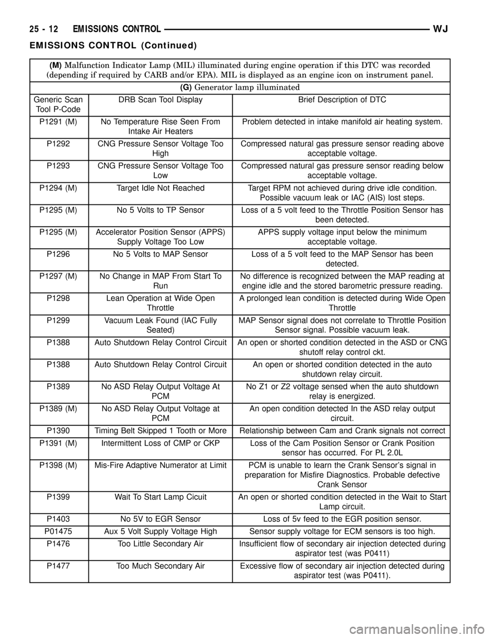
(M)Malfunction Indicator Lamp (MIL) illuminated during engine operation if this DTC was recorded
(depending if required by CARB and/or EPA). MIL is displayed as an engine icon on instrument panel.
(G)Generator lamp illuminated
Generic Scan
Tool P-CodeDRB Scan Tool Display Brief Description of DTC
P1291 (M) No Temperature Rise Seen From
Intake Air HeatersProblem detected in intake manifold air heating system.
P1292 CNG Pressure Sensor Voltage Too
HighCompressed natural gas pressure sensor reading above
acceptable voltage.
P1293 CNG Pressure Sensor Voltage Too
LowCompressed natural gas pressure sensor reading below
acceptable voltage.
P1294 (M) Target Idle Not Reached Target RPM not achieved during drive idle condition.
Possible vacuum leak or IAC (AIS) lost steps.
P1295 (M) No 5 Volts to TP Sensor Loss of a 5 volt feed to the Throttle Position Sensor has
been detected.
P1295 (M) Accelerator Position Sensor (APPS)
Supply Voltage Too LowAPPS supply voltage input below the minimum
acceptable voltage.
P1296 No 5 Volts to MAP Sensor Loss of a 5 volt feed to the MAP Sensor has been
detected.
P1297 (M) No Change in MAP From Start To
RunNo difference is recognized between the MAP reading at
engine idle and the stored barometric pressure reading.
P1298 Lean Operation at Wide Open
ThrottleA prolonged lean condition is detected during Wide Open
Throttle
P1299 Vacuum Leak Found (IAC Fully
Seated)MAP Sensor signal does not correlate to Throttle Position
Sensor signal. Possible vacuum leak.
P1388 Auto Shutdown Relay Control Circuit An open or shorted condition detected in the ASD or CNG
shutoff relay control ckt.
P1388 Auto Shutdown Relay Control Circuit An open or shorted condition detected in the auto
shutdown relay circuit.
P1389 No ASD Relay Output Voltage At
PCMNo Z1 or Z2 voltage sensed when the auto shutdown
relay is energized.
P1389 (M) No ASD Relay Output Voltage at
PCMAn open condition detected In the ASD relay output
circuit.
P1390 Timing Belt Skipped 1 Tooth or More Relationship between Cam and Crank signals not correct
P1391 (M) Intermittent Loss of CMP or CKP Loss of the Cam Position Sensor or Crank Position
sensor has occurred. For PL 2.0L
P1398 (M) Mis-Fire Adaptive Numerator at Limit PCM is unable to learn the Crank Sensor's signal in
preparation for Misfire Diagnostics. Probable defective
Crank Sensor
P1399 Wait To Start Lamp Cicuit An open or shorted condition detected in the Wait to Start
Lamp circuit.
P1403 No 5V to EGR Sensor Loss of 5v feed to the EGR position sensor.
P01475 Aux 5 Volt Supply Voltage High Sensor supply voltage for ECM sensors is too high.
P1476 Too Little Secondary Air Insufficient flow of secondary air injection detected during
aspirator test (was P0411)
P1477 Too Much Secondary Air Excessive flow of secondary air injection detected during
aspirator test (was P0411).
25 - 12 EMISSIONS CONTROLWJ
EMISSIONS CONTROL (Continued)
Page 2175 of 2199

an associated limp in will take two trips to illumi-
nate the MIL.
Refer to the Diagnostic Trouble Codes Description
Charts in this section and the appropriate Power-
train Diagnostic Procedure Manual for diagnostic
procedures.
DESCRIPTION - NON-MONITORED CIRCUITS
The PCM does not monitor the following circuits,
systems and conditions that could have malfunctions
causing driveability problems. The PCM might not
store diagnostic trouble codes for these conditions.
However, problems with these systems may cause the
PCM to store diagnostic trouble codes for other sys-
tems or components. For example, a fuel pressure
problem will not register a fault directly, but could
cause a rich/lean condition or misfire. This could
cause the PCM to store an oxygen sensor or misfire
diagnostic trouble code
FUEL PRESSURE
The fuel pressure regulator controls fuel system
pressure. The PCM cannot detect a clogged fuel
pump inlet filter, clogged in-line fuel filter, or a
pinched fuel supply or return line. However, these
could result in a rich or lean condition causing the
PCM to store an oxygen sensor or fuel system diag-
nostic trouble code.
SECONDARY IGNITION CIRCUIT
The PCM cannot detect an inoperative ignition coil,
fouled or worn spark plugs, ignition cross firing, or
open spark plug cables.
CYLINDER COMPRESSION
The PCM cannot detect uneven, low, or high engine
cylinder compression.
EXHAUST SYSTEM
The PCM cannot detect a plugged, restricted or
leaking exhaust system, although it may set a fuel
system fault.
FUEL INJECTOR MECHANICAL MALFUNCTIONS
The PCM cannot determine if a fuel injector is
clogged, the needle is sticking or if the wrong injectoris installed. However, these could result in a rich or
lean condition causing the PCM to store a diagnostic
trouble code for either misfire, an oxygen sensor, or
the fuel system.
EXCESSIVE OIL CONSUMPTION
Although the PCM monitors engine exhaust oxygen
content when the system is in closed loop, it cannot
determine excessive oil consumption.
THROTTLE BODY AIRFLOW
The PCM cannot detect a clogged or restricted air
cleaner inlet or filter element.
VACUUM ASSIST
The PCM cannot detect leaks or restrictions in the
vacuum circuits of vacuum assisted engine control
system devices. However, these could cause the PCM
to store a MAP sensor diagnostic trouble code and
cause a high idle condition.
PCM SYSTEM GROUND
The PCM cannot determine a poor system ground.
However, one or more diagnostic trouble codes may
be generated as a result of this condition. The mod-
ule should be mounted to the body at all times, also
during diagnostic.
PCM CONNECTOR ENGAGEMENT
The PCM may not be able to determine spread or
damaged connector pins. However, it might store
diagnostic trouble codes as a result of spread connec-
tor pins.
DESCRIPTION - HIGH AND LOW LIMITS
The PCM compares input signal voltages from each
input device with established high and low limits for
the device. If the input voltage is not within limits
and other criteria are met, the PCM stores a diagnos-
tic trouble code in memory. Other diagnostic trouble
code criteria might include engine RPM limits or
input voltages from other sensors or switches that
must be present before verifying a diagnostic trouble
code condition.
DESCRIPTION - LOAD VALUE
ENGINE IDLE/NEUTRAL 2500 RPM/NEUTRAL
All Engines 2% to 8% of Maximum Load 9% to 17% of Maximum Load
25 - 20 EMISSIONS CONTROLWJ
EMISSIONS CONTROL (Continued)
Page 2182 of 2199

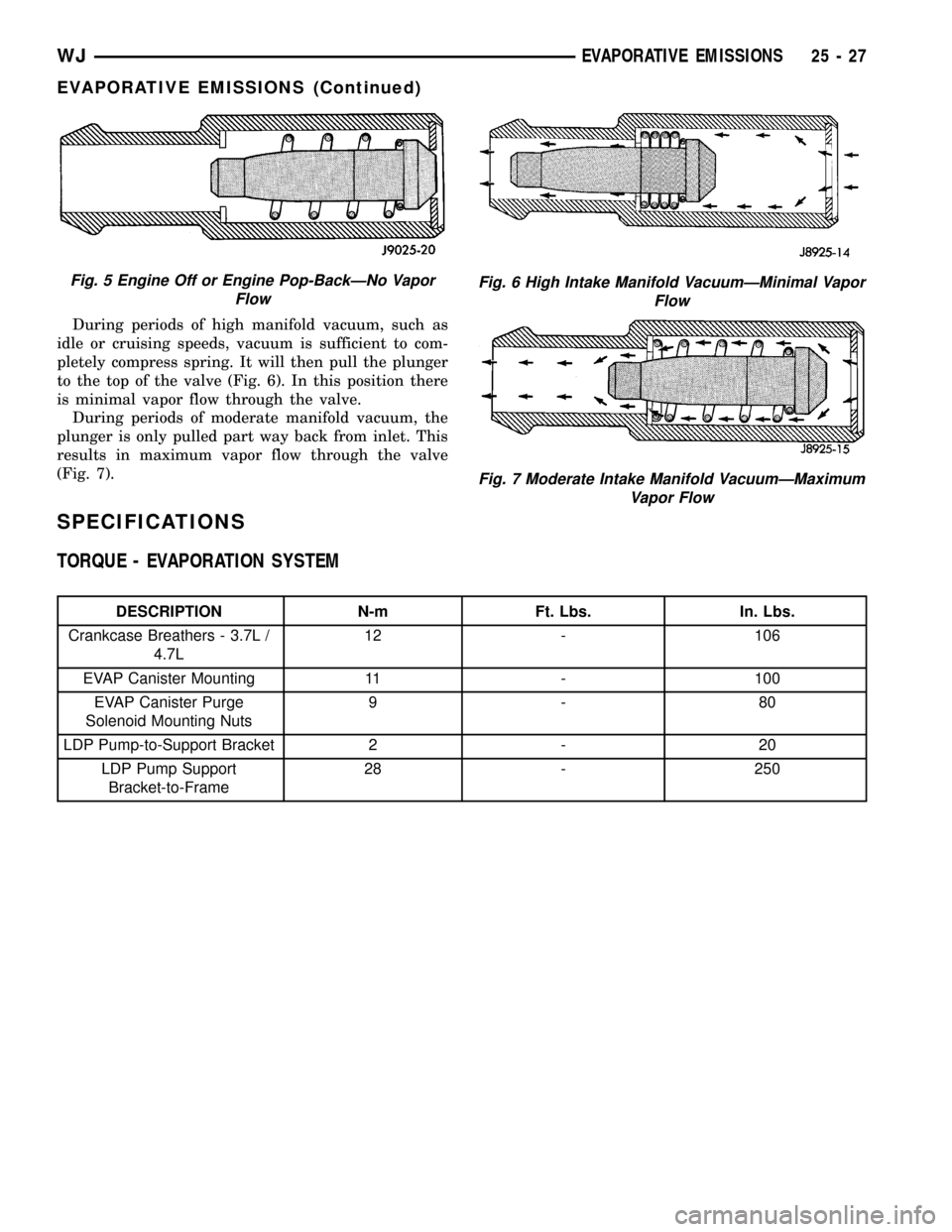
During periods of high manifold vacuum, such as
idle or cruising speeds, vacuum is sufficient to com-
pletely compress spring. It will then pull the plunger
to the top of the valve (Fig. 6). In this position there
is minimal vapor flow through the valve.
During periods of moderate manifold vacuum, the
plunger is only pulled part way back from inlet. This
results in maximum vapor flow through the valve
(Fig. 7).
SPECIFICATIONS
TORQUE - EVAPORATION SYSTEM
DESCRIPTION N-m Ft. Lbs. In. Lbs.
Crankcase Breathers - 3.7L /
4.7L12 - 106
EVAP Canister Mounting 11 - 100
EVAP Canister Purge
Solenoid Mounting Nuts9- 80
LDP Pump-to-Support Bracket 2 - 20
LDP Pump Support
Bracket-to-Frame28 - 250
Fig. 5 Engine Off or Engine Pop-BackÐNo Vapor
FlowFig. 6 High Intake Manifold VacuumÐMinimal Vapor
Flow
Fig. 7 Moderate Intake Manifold VacuumÐMaximum
Vapor Flow
WJEVAPORATIVE EMISSIONS 25 - 27
EVAPORATIVE EMISSIONS (Continued)