2003 JEEP GRAND CHEROKEE Vacuum lines
[x] Cancel search: Vacuum linesPage 177 of 2199
INSTALLATION.........................23
MASTER CYLINDER
DESCRIPTION.........................23
OPERATION...........................24
DIAGNOSIS AND TESTING - MASTER
CYLINDER/POWER BOOSTER...........24
STANDARD PROCEDURE - MASTER
CYLINDER BLEEDING PROCEDURE......25
REMOVAL.............................25
INSTALLATION.........................25
PEDAL
DESCRIPTION
DESCRIPTION - STANDARD PEDAL.......25
DESCRIPTION - ADJUSTABLE PEDALS....25
OPERATION...........................26
REMOVAL
REMOVAL - NON-ADJUSTABLE PEDAL....26
REMOVAL - ADJUSTABLE PEDALS........27
INSTALLATION
INSTALLATION - NON-ADJUSTABLE PEDAL . 28
INSTALLATION - ADJUSTABLE PEDALS....28
PEDAL MOTOR
REMOVAL.............................28
INSTALLATION.........................28
POWER BRAKE BOOSTER
DESCRIPTION.........................29
OPERATION...........................29
REMOVAL.............................31
INSTALLATION.........................31
ROTORS
DIAGNOSIS AND TESTING
DIAGNOSIS AND TESTING - FRONT DISC
BRAKE ROTOR.......................31DIAGNOSIS AND TESTING - REAR DISC
BRAKE ROTOR.......................32
STANDARD PROCEDURE - DISC ROTOR
MACHINING..........................33
REMOVAL
REMOVAL - FRONT DISC BRAKE ROTOR . . 33
REMOVAL - REAR DISC BRAKE ROTOR . . . 33
INSTALLATION
INSTALLATION - FRONT DISC BRAKE
ROTOR .............................34
INSTALLATION - REAR DISC BRAKE
ROTOR .............................34
PARKING BRAKE
OPERATION...........................34
DIAGNOSIS AND TESTING - PARKING BRAKE . 34
CABLES
REMOVAL
REMOVAL - FRONT PARKING BRAKE
CABLE..............................35
REMOVAL - REAR PARKING BRAKE
CABLES............................36
INSTALLATION
INSTALLATION - FRONT PARKING BRAKE
CABLE..............................37
INSTALLATION - REAR PARKING BRAKE
CABLES............................37
LEVER
REMOVAL.............................38
INSTALLATION.........................39
SHOES
REMOVAL.............................39
INSTALLATION.........................39
ADJUSTMENTS - PARKING BRAKE SHOE....40
BRAKES - BASE
DESCRIPTION
Dual piston disc brake calipers are used on the
front. Single piston disc brake calipers are used on
the rear. Ventilated disc brake rotors are used on the
front and solid rotors are used on the rear.
Power brake assist is supplied by a vacuum oper-
ated, dual diaphragm power brake booster. The mas-
ter cylinder used for all applications has an
aluminum body and nylon reservoir with single filler
cap. A fluid level indicator is mounted to the side of
the reservoir.
The braking force of the rear wheels is controlled
by electronic brake distribution (EBD). The EBD
functions like a rear proportioning valve. The EBD
system uses the ABS system to control the slip of the
rear wheels in partial braking range. The braking
force of the rear wheels is controlled electronically by
using the inlet and outlet valves located in the HCU.
Factory installed brake linings on all models con-
sists of organic base material combined with metallic
particles.
DIAGNOSIS AND TESTING - BASE BRAKE
SYSTEM
Base brake components consist of the brake shoes,
calipers, rear park brake drums/rotors, front brake
rotors, brake lines, master cylinder, booster, HCU
and parking brake shoes.
Brake diagnosis involves determining if the prob-
lem is related to a mechanical, hydraulic, electrical
or vacuum operated component.
The first diagnosis step is the preliminary check.
PRELIMINARY BRAKE CHECK
(1) Check condition of tires and wheels. Damaged
wheels and worn, damaged, or underinflated tires
can cause pull, shudder, vibration, and a condition
similar to grab.
5 - 2 BRAKES - BASEWJ
Page 178 of 2199
(2) If complaint was based on noise when braking,
check suspension components. Jounce front and rear
of vehicle and listen for noise that might be caused
by loose, worn or damaged suspension or steering
components.
(3) Inspect brake fluid level and condition. Note
that the brake reservoir fluid level will decrease in
proportion to normal lining wear.Also note that
brake fluid tends to darken over time. This is
normal and should not be mistaken for contam-
ination.
(a) If fluid level is abnormally low, look for evi-
dence of leaks at calipers, brake lines, master cyl-
inder, and HCU.
(b) If fluid appears contaminated, drain out a
sample to examine. System will have to be flushed
if fluid is separated into layers, or contains a sub-
stance other than brake fluid. The system seals,
cups, hoses, master cylinder, and HCU will also
have to be replaced after flushing. Use clean brake
fluid to flush the system.
(4) Check parking brake operation. Verify free
movement and full release of cables and lever. Also
note if vehicle was being operated with parking
brake partially applied.
(5) Check brake pedal operation. Verify that pedal
does not bind and has adequate free play. If pedal
lacks free play, check pedal and power booster for
being loose or for bind condition. Do not road test
until condition is corrected.
(6) Check booster vacuum check valve and hose.
(7) If components checked appear OK, road test
the vehicle.
ROAD TESTING
(1) If complaint involved low brake pedal, pump
pedal and note if it comes back up to normal height.
(2) Check brake pedal response with transmission
in neutral and engine running. Pedal should remain
firm under constant foot pressure.
(3) During road test, make normal and firm brake
stops in 25-40 mph range. Note faulty brake opera-
tion such as low pedal, hard pedal, fade, pedal pulsa-
tion, pull, grab, drag, noise, etc.
(4) Attempt to stop the vehicle with the parking
brake only (do not exceed 25 mph) and note grab,
drag, noise, etc.
PEDAL FALLS AWAY
A brake pedal that falls away under steady foot
pressure is generally the result of a system leak. The
leak point could be at a brake line, fitting, hose, or
caliper. If leakage is severe, fluid will be evident at
or around the leaking component.Internal leakage (seal by-pass) in the master cylin-
der caused by worn or damaged piston cups, may
also be the problem cause.
An internal leak in the ABS system may also be
the problem with no visual fluid leak.
LOW PEDAL
If a low pedal is experienced, pump the pedal sev-
eral times. If the pedal comes back up, the most
likely causes are worn linings, rotors, or calipers are
not sliding on the slide pins. The proper course of
action is to inspect and replace all worn component.
SPONGY PEDAL
A spongy pedal is most often caused by air in the
system. However substandard brake hoses can cause
a spongy pedal. The proper course of action is to
bleed the system, and replace substandard quality
brake hoses if suspected.
HARD PEDAL OR HIGH PEDAL EFFORT
A hard pedal or high pedal effort may be due to
lining that is water soaked, contaminated, glazed, or
badly worn. The power booster, check valve, check
valve seal/grommet or vacuum leak could also cause
a hard pedal or high pedal effort.
PEDAL PULSATION
Pedal pulsation is caused by components that are
loose, or beyond tolerance limits.
The primary cause of pulsation are disc brake
rotors with excessive lateral runout or thickness vari-
ation. Other causes are loose wheel bearings or cali-
pers and worn, damaged tires.
NOTE: Some pedal pulsation may be felt during
ABS activation.
BRAKE DRAG
Brake drag occurs when the lining is in constant
contact with the rotor or drum. Drag can occur at one
wheel, all wheels, fronts only, or rears only.
Drag is a product of incomplete brake release.
Drag can be minor or severe enough to overheat the
linings, rotors and park brake drums.
Minor drag will usually cause slight surface charring
of the lining. It can also generate hard spots in rotors
and park brake drums from the overheat-cool down pro-
cess. In most cases, the rotors, wheels and tires are
quite warm to the touch after the vehicle is stopped.
Severe drag can char the brake lining all the way
through. It can also distort and score rotors to the
point of replacement. The wheels, tires and brake
components will be extremely hot. In severe cases,
the lining may generate smoke as it chars from over-
heating.
WJBRAKES - BASE 5 - 3
BRAKES - BASE (Continued)
Page 589 of 2199

(4) Install airbag module. Refer to Group 8M, Pas-
sive Restraint Systems.
(5) Connect negative battery cable.
VACUUM RESERVOIR
DESCRIPTION
The vacuum reservoir is a plastic storage tank con-
nected to an engine vacuum source by vacuum lines.
OPERATION
The vacuum reservoir is used to supply the vac-
uum needed to maintain proper speed control opera-
tion when engine vacuum drops, such as in climbing
a grade while driving. A one-way check valve is used
in the vacuum line between the reservoir and the
vacuum source. This check valve is used to trap
engine vacuum in the reservoir. On certain vehicle
applications, this reservoir is shared with the heat-
ing/air-conditioning system. The vacuum reservoir
cannot be repaired and must be replaced if faulty.
DIAGNOSIS AND TESTING - VACUUM
RESERVOIR
(1) Disconnect vacuum hose at speed control servo
and install a vacuum gauge into the disconnected
hose.
(2) Start engine and observe gauge at idle. Vac-
uum gauge should read at least ten inches of mer-
cury.
(3) If vacuum is less than ten inches of mercury,
determine source of leak. Check vacuum line to
engine for leaks. Also check actual engine intake
manifold vacuum. If manifold vacuum does not meet
this requirement, check for poor engine performance
and repair as necessary.
(4) If vacuum line to engine is not leaking, check
for leak at vacuum reservoir. To locate and gain
access to reservoir, refer to Vacuum Reservoir Remov-
al/Installation in this group. Disconnect vacuum line
at reservoir and connect a hand-operated vacuum
pump to reservoir fitting. Apply vacuum. Reservoir
vacuum should not bleed off. If vacuum is being lost,
replace reservoir.
(5) Verify operation of one-way check valve and
check it for leaks.
(a) Locate one-way check valve. The valve is
located in vacuum line between vacuum reservoir
and engine vacuum source. Disconnect vacuum
hoses (lines) at each end of valve.
(b) Connect a hand-operated vacuum pump to
reservoir end of check valve. Apply vacuum. Vac-
uum should not bleed off. If vacuum is being lost,
replace one-way check valve.
(c) Connect a hand-operated vacuum pump to
vacuum source end of check valve. Apply vacuum.
Vacuum should flow through valve. If vacuum is
not flowing, replace one-way check valve. Seal the
fitting at opposite end of valve with a finger and
apply vacuum. If vacuum will not hold, diaphragm
within check valve has ruptured. Replace valve.
REMOVAL
The vacuum reservoir is located in the right/front
corner of the vehicle behind the front bumper fascia
(Fig. 8).
(1) Remove front bumper and grill assembly.
(2) Remove 1 support bolt near front of reservoir
(Fig. 8).
(3) Remove 2 reservoir mounting bolts.
(4) Remove reservoir from vehicle to gain access to
vacuum hose (Fig. 9). Disconnect vacuum hose from
reservoir fitting at rear of reservoir.
Fig. 7 Speed Control Switches
1 - MOUNTING SCREW
2 - SPEED CONTROL SWITCHES
8P - 8 SPEED CONTROLWJ
SWITCH (Continued)
Page 1421 of 2199
FUEL DELIVERY
DESCRIPTION
The fuel delivery system consists of:
²the fuel pump module containing the electric
fuel pump, fuel gauge sending unit (fuel level sensor)
and a separate fuel filter located at bottom of pump
module
²a separate combination fuel filter/fuel pressure
regulator
²fuel tubes/lines/hoses
²quick-connect fittings
²fuel injector rail
²fuel injectors
²fuel tank
²fuel tank filler/vent tube assembly
²fuel tank filler tube cap
²accelerator pedal
²throttle cable
OPERATION
The fuel tank assembly consists of: the fuel tank,
fuel tank shield, fuel tank straps, fuel pump module
assembly, fuel pump module locknut/gasket, and fuel
tank check valve (refer to Emission Control System
for fuel tank check valve information).
A fuel filler/vent tube assembly using a pressure/
vacuum, 1/4 turn fuel filler cap is used. The fuel
filler tube contains a flap door located below the fuel
fill cap.
Also to be considered part of the fuel system is the
evaporation control system. This is designed to
reduce the emission of fuel vapors into the atmo-
sphere. The description and function of the Evapora-
tive Control System is found in Emission Control
Systems.
Both fuel filters (at bottom of fuel pump module
and within fuel pressure regulator) are designed for
extended service. They do not require normal sched-
uled maintenance. Filters should only be replaced if
a diagnostic procedure indicates to do so.
DIAGNOSIS AND TESTING
FUEL PRESSURE LEAK DOWN TEST
Use this test in conjunction with the Fuel Pump
Pressure Test and Fuel Pump Capacity Test.
Check Valve Operation:The electric fuel pump
outlet contains a one-way check valve to prevent fuel
flow back into the tank and to maintain fuel supply
line pressure (engine warm) when pump is not oper-
ational. It is also used to keep the fuel supply line
full of gasoline when pump is not operational. After
the vehicle has cooled down, fuel pressure may drop
to 0 psi (cold fluid contracts), but liquid gasoline willremain in fuel supply line between the check valve
and fuel injectors.Fuel pressure that has
dropped to 0 psi on a cooled down vehicle
(engine off) is a normal condition.When the elec-
tric fuel pump is activated, fuel pressure should
immediately(1±2 seconds) rise to specification.
Abnormally long periods of cranking to restart a
hotengine that has been shut down for a short
period of time may be caused by:
²Fuel pressure bleeding past a fuel injector(s).
²Fuel pressure bleeding past the check valve in
the fuel pump module.
²A defective fuel filter/pressure regulator.
Two #6539, 5/16º, Fuel Line Pressure Test Adapter
Hose Tools are required for the following tests.
(1) Release fuel system pressure. Refer to Fuel
Pressure Release Procedure.
(2) Raise vehicle.
Fuel Line Identification:The fuel filter/pressure
regulator is located in front of the fuel tank and
above the rear axle. It is transversely mounted to a
chassis crossmember (left-to-right). The filter/regula-
tor is equipped with 3 fuel line fittings (2 at one end
and 1 at the other end). The single fitting facing the
left side of the vehicle is the supply line to the fuel
rail (Fig. 1) . The 2 fittings facing the right side of
the vehicle are connected to the fuel tank. Of these 2
fittings, the fitting towards thefrontis used for fuel
return to the fuel tank. The fitting towards therear
is a pressure line. Thisrearfitting must be discon-
nected for the following step.
(3) See previous step. Disconnect fuel pressure line
atrearof filter/regulator. This is a 5/169quick-con-
nect fitting (Fig. 1) . Refer to Quick-Connect Fittings
for procedures.
(4) Obtain correct Fuel Line Pressure Test Adapter
Hose Tool # 6539 for 5/16º fuel lines. Connect one
end of this Special Tool into the disconnected fuel
pressure line. Connect the other end of the Tool into
fitting on filter/regulator.
(5) Lower vehicle.
(6) Disconnect the fuel inlet line at fuel rail. Refer
to Quick-Connect Fittings for procedures. On some
engines, air cleaner housing removal may be neces-
sary before fuel line disconnection.
(7) Obtain a second Fuel Line Pressure Test
Adapter Hose Tool # 6539 for 5/16º fuel lines. Con-
nect this tool between disconnected fuel line and fuel
rail (Fig. 2) .
(8) Connect the 0-414 kPa (0-60 psi) fuel pressure
test gauge (from Gauge Set 5069) to the test port on
the appropriate Adaptor Tool.NOTE: The DRB III
Scan Tool along with the PEP module, the 500
psi pressure transducer, and the transducer-to-
test port adapter may also be used in place of
the fuel pressure gauge.
14 - 2 FUEL DELIVERYWJ
Page 1435 of 2199
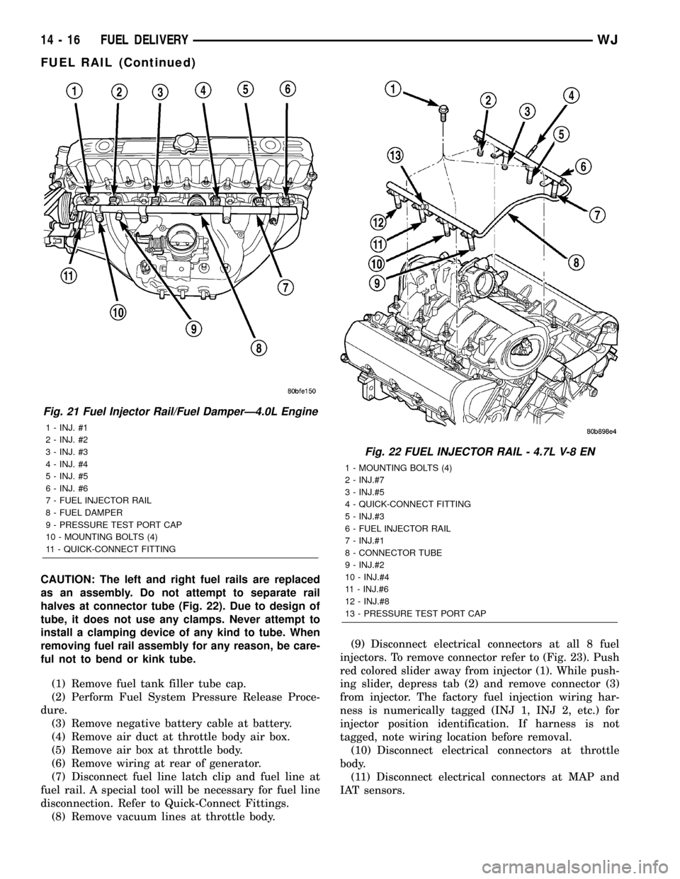
CAUTION: The left and right fuel rails are replaced
as an assembly. Do not attempt to separate rail
halves at connector tube (Fig. 22). Due to design of
tube, it does not use any clamps. Never attempt to
install a clamping device of any kind to tube. When
removing fuel rail assembly for any reason, be care-
ful not to bend or kink tube.
(1) Remove fuel tank filler tube cap.
(2) Perform Fuel System Pressure Release Proce-
dure.
(3) Remove negative battery cable at battery.
(4) Remove air duct at throttle body air box.
(5) Remove air box at throttle body.
(6) Remove wiring at rear of generator.
(7) Disconnect fuel line latch clip and fuel line at
fuel rail. A special tool will be necessary for fuel line
disconnection. Refer to Quick-Connect Fittings.
(8) Remove vacuum lines at throttle body.(9) Disconnect electrical connectors at all 8 fuel
injectors. To remove connector refer to (Fig. 23). Push
red colored slider away from injector (1). While push-
ing slider, depress tab (2) and remove connector (3)
from injector. The factory fuel injection wiring har-
ness is numerically tagged (INJ 1, INJ 2, etc.) for
injector position identification. If harness is not
tagged, note wiring location before removal.
(10) Disconnect electrical connectors at throttle
body.
(11) Disconnect electrical connectors at MAP and
IAT sensors.
Fig. 21 Fuel Injector Rail/Fuel DamperÐ4.0L Engine
1 - INJ. #1
2 - INJ. #2
3 - INJ. #3
4 - INJ. #4
5 - INJ. #5
6 - INJ. #6
7 - FUEL INJECTOR RAIL
8 - FUEL DAMPER
9 - PRESSURE TEST PORT CAP
10 - MOUNTING BOLTS (4)
11 - QUICK-CONNECT FITTING
Fig. 22 FUEL INJECTOR RAIL - 4.7L V-8 EN
1 - MOUNTING BOLTS (4)
2 - INJ.#7
3 - INJ.#5
4 - QUICK-CONNECT FITTING
5 - INJ.#3
6 - FUEL INJECTOR RAIL
7 - INJ.#1
8 - CONNECTOR TUBE
9 - INJ.#2
10 - INJ.#4
11 - INJ.#6
12 - INJ.#8
13 - PRESSURE TEST PORT CAP
14 - 16 FUEL DELIVERYWJ
FUEL RAIL (Continued)
Page 1437 of 2199
(9) Disconnect speed control cable at throttle body
(if equipped). Refer to Speed Control Cable.
(10) Disconnect automatic transmission cable at
throttle body (if equipped).
(11) Remove cable routing bracket at intake mani-
fold.
(12) Clean dirt/debris from each fuel injector at
intake manifold.
(13) Remove fuel rail mounting nuts/bolts (Fig.
24).
(14) Remove fuel rail by gently rocking until all
fuel injectors have cleared machined holes at intake
manifold.
(15) If fuel injectors are to be removed, refer to
Fuel Injector Removal/Installation.
INSTALLATION
INSTALLATION - 4.7L
(1) If fuel injectors are to be installed, refer to Fuel
Injector Removal/Installation.
(2) Apply a small amount of engine oil to each fuel
injector o-ring. This will help in fuel rail installation.
(3) Position fuel rail/fuel injector assembly to
machined injector openings in cylinder head.
(4) Guide each injector into cylinder head. Be care-
ful not to tear injector o-rings.(5) Pushrightside of fuel rail down until fuel
injectors have bottomed on cylinder head shoulder.
Pushleftfuel rail down until injectors have bot-
tomed on cylinder head shoulder.
(6) Install 4 fuel rail mounting bolts and tighten to
27 N´m (20 ft. lbs.).
(7) Install ignition coils. Refer to Ignition Coil
Removal/Installation.
(8) Connect electrical connectors to throttle body.
(9) Connect electrical connectors to MAP and IAT
sensors.
(10) Connect electrical connectors at all fuel injec-
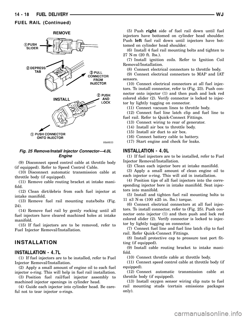
tors. To install connector, refer to (Fig. 23). Push con-
nector onto injector (1) and then push and lock red
colored slider (2). Verify connector is locked to injec-
tor by lightly tugging on connector.
(11) Connect vacuum lines to throttle body.
(12) Connect fuel line latch clip and fuel line to
fuel rail. Refer to Quick-Connect Fittings.
(13) Connect wiring to rear of generator.
(14) Install air box to throttle body.
(15) Install air duct to air box.
(16) Connect battery cable to battery.
(17) Start engine and check for leaks.
INSTALLATION - 4.0L
(1) If fuel injectors are to be installed, refer to Fuel
Injector Removal/Installation.
(2) Clean each injector bore at intake manifold.
(3) Apply a small amount of clean engine oil to
each injector o-ring. This will aid in installation.
(4) Position tips of all fuel injectors into the corre-
sponding injector bore in intake manifold. Seat injec-
tors into manifold.
(5) Install and tighten fuel rail mounting bolts to
11 3 N´m (100 25 in. lbs.) torque.
(6) Connect electrical connectors at all fuel injec-
tors. To install connector, refer to (Fig. 25). Push con-
nector onto injector (1) and then push and lock red
colored slider (2). Verify connector is locked to injec-
tor by lightly tugging on connector.
(7) Connect fuel line and fuel line latch clip to fuel
rail. Refer Quick-Connect Fittings.
(8) Install protective cap to pressure test port fit-
ting (if equipped).
(9) Install cable routing bracket to intake mani-
fold.
(10) Connect throttle cable at throttle body.
(11) Connect speed control cable at throttle body (if
equipped).
(12) Connect automatic transmission cable at
throttle body (if equipped).
(13) Install oxygen sensor wiring clip nuts to fuel
rail mounting studs (certain emissions packages
only).
Fig. 25 Remove/Install Injector ConnectorÐ4.0L
Engine
14 - 18 FUEL DELIVERYWJ
FUEL RAIL (Continued)
Page 1438 of 2199

(14) Install air tube (or duct) at top of throttle
body.
(15) Install fuel tank cap.
(16) Connect negative battery cable to battery.
(17) Start engine and check for fuel leaks.
FUEL TANK
DESCRIPTION
The fuel tank is constructed of a plastic material.
Its main functions are for fuel storage and for place-
ment of the fuel pump module and certain ORVR
components.
OPERATION
All models pass a full 360 degree rollover test
without fuel leakage. To accomplish this, fuel and
vapor flow controls are required for all fuel tank con-
nections.
A fuel tank check valve(s) is mounted into the top
of the fuel tank (or pump module). Refer to Fuel
Tank Check Valve for additional information.
An evaporation control system is connected to the
check valve(s) to reduce emissions of fuel vapors into
the atmosphere. When fuel evaporates from the fuel
tank, vapors pass through vent hoses or tubes to a
charcoal canister where they are temporarily held.
When the engine is running, the vapors are drawn
into the intake manifold. Certain models are also
equipped with a self-diagnosing system using a Leak
Detection Pump (LDP). Refer to Emission Control
System for additional information.
Refer to ORVR for On-Board Refueling Vapor
Recovery system information.
REMOVAL
WARNING: THE FUEL SYSTEM IS UNDER CON-
STANT FUEL PRESSURE EVEN WITH ENGINE OFF.
PRESSURE MUST BE RELEASED BEFORE SERVIC-
ING FUEL TANK.
Two different procedures may be used to drain fuel
tank (through ORVR control valve opening at top of
fuel tank, or using DRB scan tool). The quickest is
draining through ORVR control valve opening at top
of fuel tank (Fig. 26).
As an alternative procedure, the electric fuel pump
may be activated allowing tank to be drained at fuel
rail connection. Refer to DRB scan tool for fuel pump
activation procedures. Before disconnecting fuel line
at fuel rail, release fuel pressure. Refer to the Fuel
System Pressure Release Procedure for procedures.
Attach end of Special Adapter Hose Tool number
6539 at fuel rail disconnection. Position opposite end
of 6539 to an approved gasoline draining station.Activate fuel pump with DRB and drain tank until
empty.
If electric fuel pump is not operating, tankMUST
be drained through ORVR control valve opening at
top of fuel tank (Fig. 26).
(1) Release fuel system pressure. Refer to Fuel
System Pressure Release Procedure.
(2) Disconnect negative battery cable at battery.
(3) Raise and support vehicle.
(4) Remove left rear wheel/tire.
CAUTION: HANDLE EVAP, LDP AND ORVR VAPOR /
VACUUM LINES VERY CAREFULLY. THESE LINES
AND HOSES MUST BE FIRMLY CONNECTED.
CHECK THE VAPOR/VACUUM LINES AT THE LDP,
LDP FILTER, EVAP CANISTER, EVAP CANISTER
PURGE SOLENOID AND ORVR COMPONENTS FOR
DAMAGE OR LEAKS. IF A LEAK IS PRESENT, A
DIAGNOSTIC TROUBLE CODE (DTC) MAY BE SET.
(5) Clean top of fuel tank at ORVR control valve
(Fig. 26) or (Fig. 27).
(6) Press release tab in direction of arrow in (Fig.
27) and remove ORVR control valve lock ring
(counter-clockwise). Lift up ORVR control slightly.
Using an approved gasoline draining station, drain
tank until empty through this opening.
(7) Remove stone shield behind left/rear wheel
(Fig. 28). Drill out plastic rivets for removal.
(8) Remove 3 LDP mounting bolts (Fig. 29).
(9) Remove support bracket brace bolt (Fig. 30).
(10) Loosen, but do not remove 2 support bracket
nuts at frame rail (Fig. 29).
(11) To separate and lower front section of two-
piece support bracket, remove 3 attaching bolts on
bottom of support bracket (Fig. 30). While lowering
support bracket, disconnect LDP wiring clip (Fig. 31).
(12) Remove hose clamp (Fig. 32) and remove fuel
fill hose from fuel fill tube.
(13) Cut and discard tie wrap from axle vent hose
(Fig. 32).
(14) Disconnect fuel vent hose from fuel vent tube
(Fig. 32).
(15) Disconnect ORVR hose elbow (Fig. 33) at top
of EVAP canister.
(16) Place hydraulic jack to bottom of fuel tank.
(17) Remove fuel tank-to-rear bumper fascia clips
(Fig. 34).
(18) Remove fuel tank heat shield mounting bolts
(Fig. 35).
CAUTION: To protect fuel tank from exhaust heat,
shield must re-installed after tank installation.
WARNING: PLACE SHOP TOWEL AROUND FUEL
LINES TO CATCH ANY EXCESS FUEL.
WJFUEL DELIVERY 14 - 19
FUEL RAIL (Continued)
Page 1439 of 2199
(19) Disconnect fuel return line at fuel filter/fuel
pressure regulator (Fig. 36). Refer to Quick-Connect
Fittings for procedures.
(20) Disconnect fuel pressure line at fuel filter/fuel
pressure regulator (Fig. 36). Refer to Quick-Connect
Fittings for procedures.
(21) Disconnect EVAP canister vent line near front
of tank (Fig. 36).
(22) Disconnect fuel pump module electrical con-
nector (pigtail harness) near front of tank (Fig. 36).
Harness connector is clipped to body.
(23) Remove left / front tank support bracket bolt
at frame (Fig. 37).
(24)WITHOUT TRAILER HITCH:Remove tank-
to-frame mounting bolts (Fig. 39). Remove rear tank
support bracket bolts at frame (Fig. 38). Carefully
lower tank until clear of vehicle. Place tank on floor.
(25)WITH TRAILER HITCH:Remove tank /
hitch mounting bolts (Fig. 40). Carefully lower tank
until clear of vehicle. Place tank on floor.
(26) If necessary, separate skid plate from fuel
tank by removing 2 fuel tank strap nuts (Fig. 39) and
remove 2 tank straps.
(27) If fuel pump module removal is necessary,
refer to Fuel Pump Module Removal/Installation.
(28) If hoses are to be removed at fuel tank end,
note painted alignment (indexing) markings on
hoses, and molded indexing tangs on tank before
removal. Remove hoses.
(29) If necessary, remove 3 fuel filler tube assem-
bly mounting bolts (Fig. 41) and remove fuel filler
tube.
INSTALLATION
CAUTION: HANDLE EVAP, LDP AND ORVR VAPOR /
VACUUM LINES VERY CAREFULLY. THESE LINES
AND HOSES MUST BE FIRMLY CONNECTED.
CHECK THE VAPOR/VACUUM LINES AT THE LDP,
LDP FILTER, EVAP CANISTER, EVAP CANISTER
PURGE SOLENOID AND ORVR COMPONENTS FOR
DAMAGE OR LEAKS. IF A LEAK IS PRESENT, A
DIAGNOSTIC TROUBLE CODE (DTC) MAY BE SET.
(1) If necessary, position fuel filler tube assembly
to body. Install 3 bolts and tighten to 2 N´m (15 in.
lbs.) torque.
(2) If necessary, connect quick-connect fittings to
fuel pump module.
(3) If fuel pump module is being installed, refer to
Fuel Pump Module Removal/Installation.
(4) Install fuel fill/vent hoses to tank fittings. To
prevent hoses from kinking, rotate each hose until
painted indexing mark on hose is aligned to molded
indexing tang on tank.
(5) Install hose clamps to hoses. Refer to Torque
Specifications.(6) If necessary, position fuel tank into skid plate.
Install 2 tank straps and 2 strap nuts (Fig. 39). Refer
to Torque Specifications.
(7) Position fuel tank / skid plate assembly to
hydraulic jack.
(8) Raise tank into position to frame.
(9)WITH TRAILER HITCH:Position trailer
hitch and tow hooks (Fig. 40) to bottom of fuel tank.
Install bolts and nuts loosely.
(10)WITHOUT TRAILER HITCH:Install 2 rear
tank support brackets and bolts (Fig. 38). Install
tank-to-frame bolts. Do not tighten bolts / nuts at
this time.
(11) Install 1 left / front tank support bracket and
bolts / nuts (Fig. 37). Do not tighten bolts / nuts at
this time.
(12) Be sure fuel tank is properly aligned to frame
and body. Tighten all tank, tow hook and trailer
hitch bolts / nuts except for 3 support brackets.
Tighten all 3 (2 rear and 1 left / front) support
bracket bolts / nuts last. Refer to Torque Specifica-
tions.
(13)
(14) Connect fuel pump module pigtail harness
electrical connector near front of tank.
(15) Connect both fuel lines to fuel filter/fuel pres-
sure regulator. Refer to Quick-Connect Fittings for
procedures.
(16) Connect EVAP hose near front of tank.
(17) Position rear axle vent hose and install new
tie strap (Fig. 32).
(18) Install heat shield nuts / bolts (Fig. 35). Refer
to Torque Specifications.
(19) Connect ORVR hose elbow (Fig. 33) to top of
EVAP canister.
(20) Connect fuel vent hose to fuel vent tube (Fig.
32).
(21) Install fuel fill hose and clamp to fuel fill tube
(Fig. 32).
(22) Install 3 LDP mounting bolts (Fig. 29).
(23) While raising support bracket, connect LDP
wiring clip (Fig. 31). Install front section of two-piece
support bracket to rear section with 3 attaching bolts
located on bottom of support bracket (Fig. 30).
(24) Install support bracket brace bolt (Fig. 30).
(25) Tighten 2 support bracket nuts at frame rail
(Fig. 29).
(26) Install fuel tank-to-rear bumper fascia clips
(Fig. 34).
(27) Using new plastic rivets, install stone shield
behind left/rear wheel (Fig. 28).
(28) Install left rear wheel/tire.
(29) Lower vehicle and connect negative battery
cable to battery.
(30) Fill tank with fuel and check for leaks.
14 - 20 FUEL DELIVERYWJ
FUEL TANK (Continued)