2003 JEEP GRAND CHEROKEE compress
[x] Cancel search: compressPage 1279 of 2199
CRANKSHAFT MAIN
BEARINGS
STANDARD PROCEDURE - FITTING
CRANKSHAFT MAIN BEARINGS
FITTING BEARINGS (CRANKSHAFT INSTALLED)
The main bearing caps, numbered (front to rear)
from 1 through 7 have an arrow to indicate the for-
ward position. The upper main bearing inserts are
grooved to provide oil channels while the lower
inserts are smooth.
Each bearing insert pair is selectively fitted to its
respective journal to obtain the specified operating
clearance. In production, the select fit is obtained by
using various-sized color-coded bearing insert pairs
as listed in the Main Bearing Fitting Chart. The
bearing color code appears on the edge of the insert.
The size is not stamped on bearing inserts used
for engine production.
The main bearing journal size (diameter) is identi-
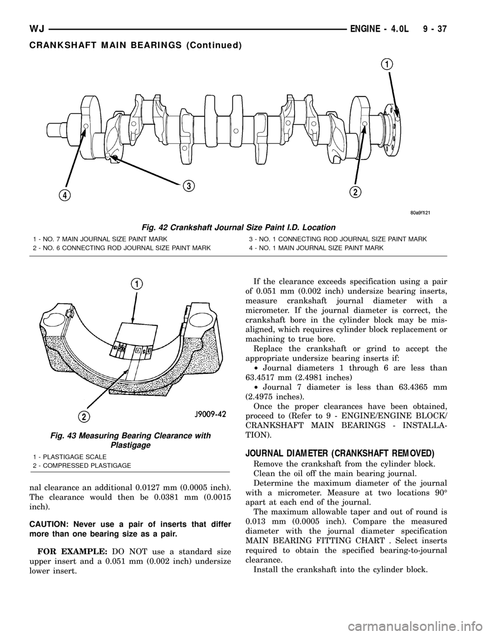
fied by a color-coded paint mark (Fig. 42)on the adja-
cent cheek or counterweight towards the rear of the
crankshaft (flange end). The rear main journal, is
identified by a color-coded paint mark on the crank-
shaft rear flange.
When required, upper and lower bearing inserts of
different sizes may be used as a pair. A standard size
insert is sometimes used in combination with a 0.025
mm (0.001 inch) undersize insert to reduce the clear-
ance by 0.013 mm (0.0005 inch).Never use a pair
of bearing inserts with greater than a 0.025 mm
(0.001 inch) difference in size. Refer to the
Bearing Insert Pair Chart.NOTE: When replacing inserts, the odd size inserts
must be either all on the top (in cylinder block) or
all on the bottom (in main bearing cap).
Once the bearings have been properly fitted, (Refer
to 9 - ENGINE/ENGINE BLOCK/CRANKSHAFT
MAIN BEARINGS - INSTALLATION).
BEARING-TO-JOURNAL CLEARANCE (CRANKSHAFT
INSTALLED)
When using Plastigage, check only one bearing
clearance at a time.
Install the grooved main bearings into the cylinder
block and the non-grooved bearings into the bearing
caps.
Install the crankshaft into the upper bearings dry.
Place a strip of Plastigage across full width of the
crankshaft journal to be checked.
Install the bearing cap and tighten the bolts to 108
N´m (80 ft. lbs.) torque.
NOTE: DO NOT rotate the crankshaft. This will
cause the Plastigage to shift, resulting in an inaccu-
rate reading. Plastigage must not be permitted to
crumble. If brittle, obtain fresh stock.
Remove the bearing cap. Determine the amount of
clearance by measuring the width of the compressed
Plastigage with the scale on the Plastigage envelope
(Fig. 43). (Refer to 9 - ENGINE - SPECIFICATIONS)
for the proper clearance.
Plastigage should indicate the same clearance
across the entire width of the insert. If clearance var-
ies, it may indicate a tapered journal or foreign
material trapped behind the insert.
If the specified clearance is indicated and there are
no abnormal wear patterns, replacement of the bear-
ing inserts is not necessary. Remove the Plastigage
from the crankshaft journal and bearing insert. Pro-
ceed to (Refer to 9 - ENGINE/ENGINE BLOCK/
CRANKSHAFT MAIN BEARINGS -
INSTALLATION).
If the clearance exceeds specification, install a pair
of 0.025 mm (0.001 inch) undersize bearing inserts
and measure the clearance as described in the previ-
ous steps.
The clearance indicate with the 0.025 mm (0.001
inch) undersize insert pair installed will determine if
this insert size or some other combination will pro-
vide the specified clearance.FOR EXAMPLE:If the
clearance was 0.0762 mm (0.003 inch) originally, a
pair of 0.0254 mm (0.001 inch) undersize inserts
would reduce the clearance by 0.0254 mm (0.001
inch). The clearance would then be 0.0508 mm (0.002
inch) and within the specification. A 0.051 mm (0.002
inch) undersize bearing insert and a 0.0254 mm
(0.001 inch) undersize insert would reduce the origi-
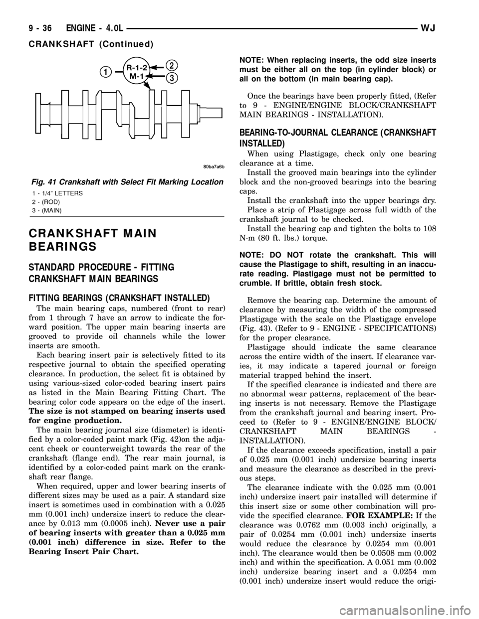
Fig. 41 Crankshaft with Select Fit Marking Location
1 - 1/4º LETTERS
2 - (ROD)
3 - (MAIN)
9 - 36 ENGINE - 4.0LWJ
CRANKSHAFT (Continued)
Page 1280 of 2199
nal clearance an additional 0.0127 mm (0.0005 inch).
The clearance would then be 0.0381 mm (0.0015
inch).
CAUTION: Never use a pair of inserts that differ
more than one bearing size as a pair.
FOR EXAMPLE:DO NOT use a standard size
upper insert and a 0.051 mm (0.002 inch) undersize
lower insert.If the clearance exceeds specification using a pair
of 0.051 mm (0.002 inch) undersize bearing inserts,
measure crankshaft journal diameter with a
micrometer. If the journal diameter is correct, the
crankshaft bore in the cylinder block may be mis-
aligned, which requires cylinder block replacement or
machining to true bore.
Replace the crankshaft or grind to accept the
appropriate undersize bearing inserts if:
²Journal diameters 1 through 6 are less than
63.4517 mm (2.4981 inches)
²Journal 7 diameter is less than 63.4365 mm
(2.4975 inches).
Once the proper clearances have been obtained,
proceed to (Refer to 9 - ENGINE/ENGINE BLOCK/
CRANKSHAFT MAIN BEARINGS - INSTALLA-
TION).
JOURNAL DIAMETER (CRANKSHAFT REMOVED)
Remove the crankshaft from the cylinder block.
Clean the oil off the main bearing journal.
Determine the maximum diameter of the journal
with a micrometer. Measure at two locations 90É
apart at each end of the journal.
The maximum allowable taper and out of round is
0.013 mm (0.0005 inch). Compare the measured
diameter with the journal diameter specification
MAIN BEARING FITTING CHART . Select inserts
required to obtain the specified bearing-to-journal
clearance.
Install the crankshaft into the cylinder block.
Fig. 42 Crankshaft Journal Size Paint I.D. Location
1 - NO. 7 MAIN JOURNAL SIZE PAINT MARK
2 - NO. 6 CONNECTING ROD JOURNAL SIZE PAINT MARK3 - NO. 1 CONNECTING ROD JOURNAL SIZE PAINT MARK
4 - NO. 1 MAIN JOURNAL SIZE PAINT MARK
Fig. 43 Measuring Bearing Clearance with
Plastigage
1 - PLASTIGAGE SCALE
2 - COMPRESSED PLASTIGAGE
WJENGINE - 4.0L 9 - 37
CRANKSHAFT MAIN BEARINGS (Continued)
Page 1289 of 2199
(11) Lower the vehicle until it is about 2 feet from
the floor.
CAUTION: Ensure that the connecting rod bolts DO
NOT scratch the crankshaft journals or cylinder
walls. Short pieces of rubber hose, slipped over the
rod bolts will provide protection during removal.
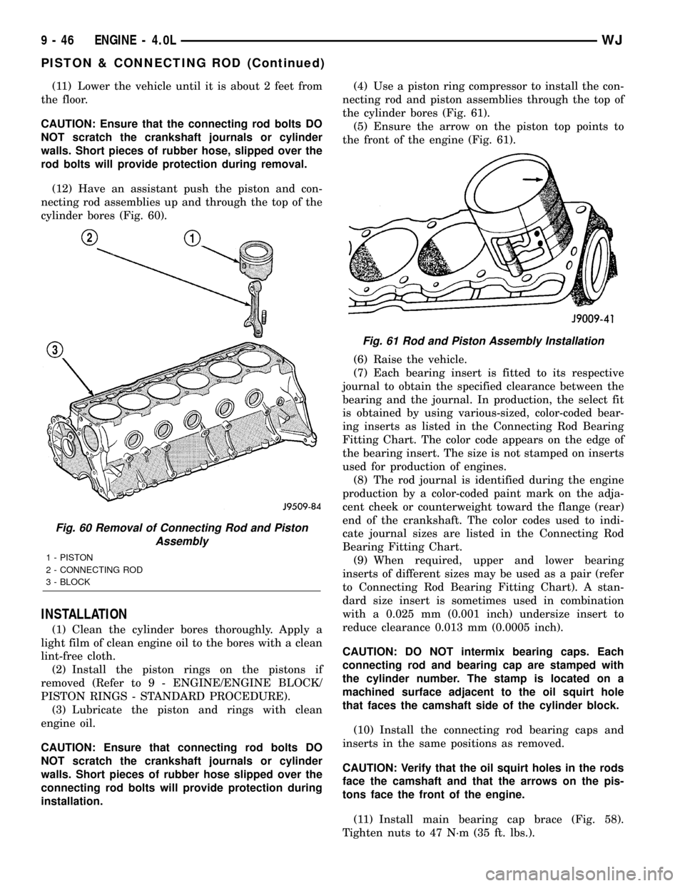
(12) Have an assistant push the piston and con-
necting rod assemblies up and through the top of the
cylinder bores (Fig. 60).
INSTALLATION
(1) Clean the cylinder bores thoroughly. Apply a
light film of clean engine oil to the bores with a clean
lint-free cloth.
(2) Install the piston rings on the pistons if
removed (Refer to 9 - ENGINE/ENGINE BLOCK/
PISTON RINGS - STANDARD PROCEDURE).
(3) Lubricate the piston and rings with clean
engine oil.
CAUTION: Ensure that connecting rod bolts DO
NOT scratch the crankshaft journals or cylinder
walls. Short pieces of rubber hose slipped over the
connecting rod bolts will provide protection during
installation.(4) Use a piston ring compressor to install the con-
necting rod and piston assemblies through the top of
the cylinder bores (Fig. 61).
(5) Ensure the arrow on the piston top points to
the front of the engine (Fig. 61).
(6) Raise the vehicle.
(7) Each bearing insert is fitted to its respective
journal to obtain the specified clearance between the
bearing and the journal. In production, the select fit
is obtained by using various-sized, color-coded bear-
ing inserts as listed in the Connecting Rod Bearing
Fitting Chart. The color code appears on the edge of
the bearing insert. The size is not stamped on inserts
used for production of engines.
(8) The rod journal is identified during the engine
production by a color-coded paint mark on the adja-
cent cheek or counterweight toward the flange (rear)
end of the crankshaft. The color codes used to indi-
cate journal sizes are listed in the Connecting Rod
Bearing Fitting Chart.
(9) When required, upper and lower bearing
inserts of different sizes may be used as a pair (refer
to Connecting Rod Bearing Fitting Chart). A stan-
dard size insert is sometimes used in combination
with a 0.025 mm (0.001 inch) undersize insert to
reduce clearance 0.013 mm (0.0005 inch).
CAUTION: DO NOT intermix bearing caps. Each
connecting rod and bearing cap are stamped with
the cylinder number. The stamp is located on a
machined surface adjacent to the oil squirt hole
that faces the camshaft side of the cylinder block.
(10) Install the connecting rod bearing caps and
inserts in the same positions as removed.
CAUTION: Verify that the oil squirt holes in the rods
face the camshaft and that the arrows on the pis-
tons face the front of the engine.
(11) Install main bearing cap brace (Fig. 58).
Tighten nuts to 47 N´m (35 ft. lbs.).
Fig. 60 Removal of Connecting Rod and Piston
Assembly
1 - PISTON
2 - CONNECTING ROD
3 - BLOCK
Fig. 61 Rod and Piston Assembly Installation
9 - 46 ENGINE - 4.0LWJ
PISTON & CONNECTING ROD (Continued)
Page 1290 of 2199
(12) Install the oil pan and gasket (Refer to 9 -
ENGINE/LUBRICATION/OIL PAN - INSTALLA-
TION).
(13) Lower the vehicle.
(14) Install the engine cylinder head (Refer to 9 -
ENGINE/CYLINDER HEAD - INSTALLATION),
push rods, rocker arms, bridges, pivots and engine
cylinder head cover(Refer to 9 - ENGINE/CYLINDER
HEAD/CYLINDER HEAD COVER(S) - INSTALLA-
TION).
(15) Fill the crankcase with engine oil.
PISTON RINGS
STANDARD PROCEDURE - PISTON RING
FITTING
(1) Carefully clean the carbon from all ring
grooves. Oil drain openings in the oil ring groove and
pin boss must be clear. DO NOT remove metal from
the grooves or lands. This will change ring-to-groove
clearances and will damage the ring-to-land seating.
(2) Be sure the piston ring grooves are free of
nicks and burrs.
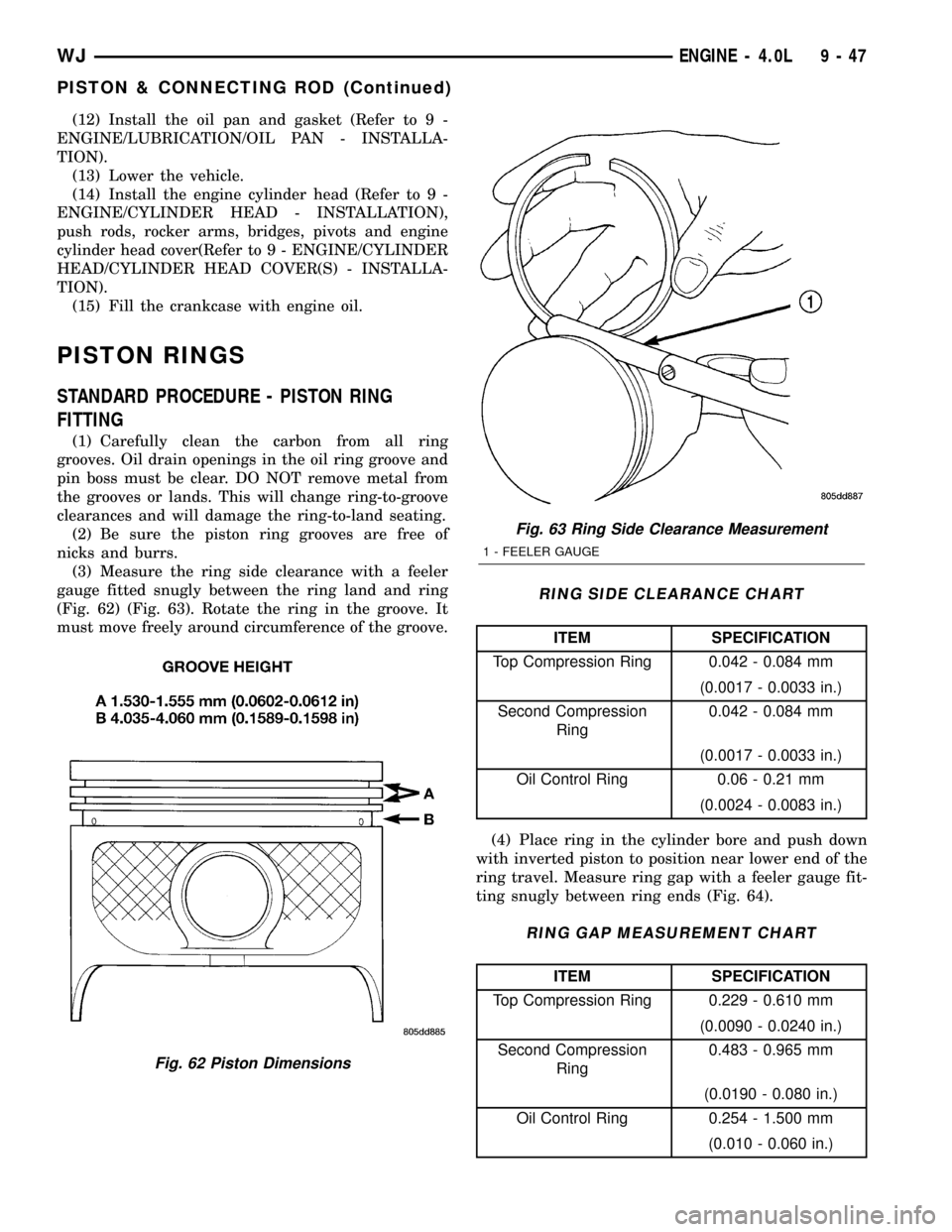
(3) Measure the ring side clearance with a feeler
gauge fitted snugly between the ring land and ring
(Fig. 62) (Fig. 63). Rotate the ring in the groove. It
must move freely around circumference of the groove.
RING SIDE CLEARANCE CHART
ITEM SPECIFICATION
Top Compression Ring 0.042 - 0.084 mm
(0.0017 - 0.0033 in.)
Second Compression
Ring0.042 - 0.084 mm
(0.0017 - 0.0033 in.)
Oil Control Ring 0.06 - 0.21 mm
(0.0024 - 0.0083 in.)
(4) Place ring in the cylinder bore and push down
with inverted piston to position near lower end of the
ring travel. Measure ring gap with a feeler gauge fit-
ting snugly between ring ends (Fig. 64).
RING GAP MEASUREMENT CHART
ITEM SPECIFICATION
Top Compression Ring 0.229 - 0.610 mm
(0.0090 - 0.0240 in.)
Second Compression
Ring0.483 - 0.965 mm
(0.0190 - 0.080 in.)
Oil Control Ring 0.254 - 1.500 mm
(0.010 - 0.060 in.)
Fig. 62 Piston Dimensions
Fig. 63 Ring Side Clearance Measurement
1 - FEELER GAUGE
WJENGINE - 4.0L 9 - 47
PISTON & CONNECTING ROD (Continued)
Page 1291 of 2199
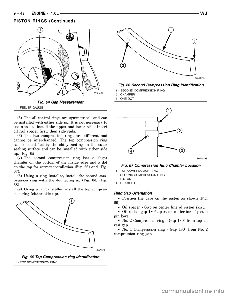
(5) The oil control rings are symmetrical, and can
be installed with either side up. It is not necessary to
use a tool to install the upper and lower rails. Insert
oil rail spacer first, then side rails.
(6) The two compression rings are different and
cannot be interchanged. The top compression ring
can be identified by the shiny coating on the outer
sealing surface and can be installed with either side
up. (Fig. 65).
(7) The second compression ring has a slight
chamfer on the bottom of the inside edge and a dot
on the top for correct installation (Fig. 66) and (Fig.
67).
(8) Using a ring installer, install the second com-
pression ring with the dot facing up (Fig. 66) (Fig.
68).
(9) Using a ring installer, install the top compres-
sion ring (either side up).
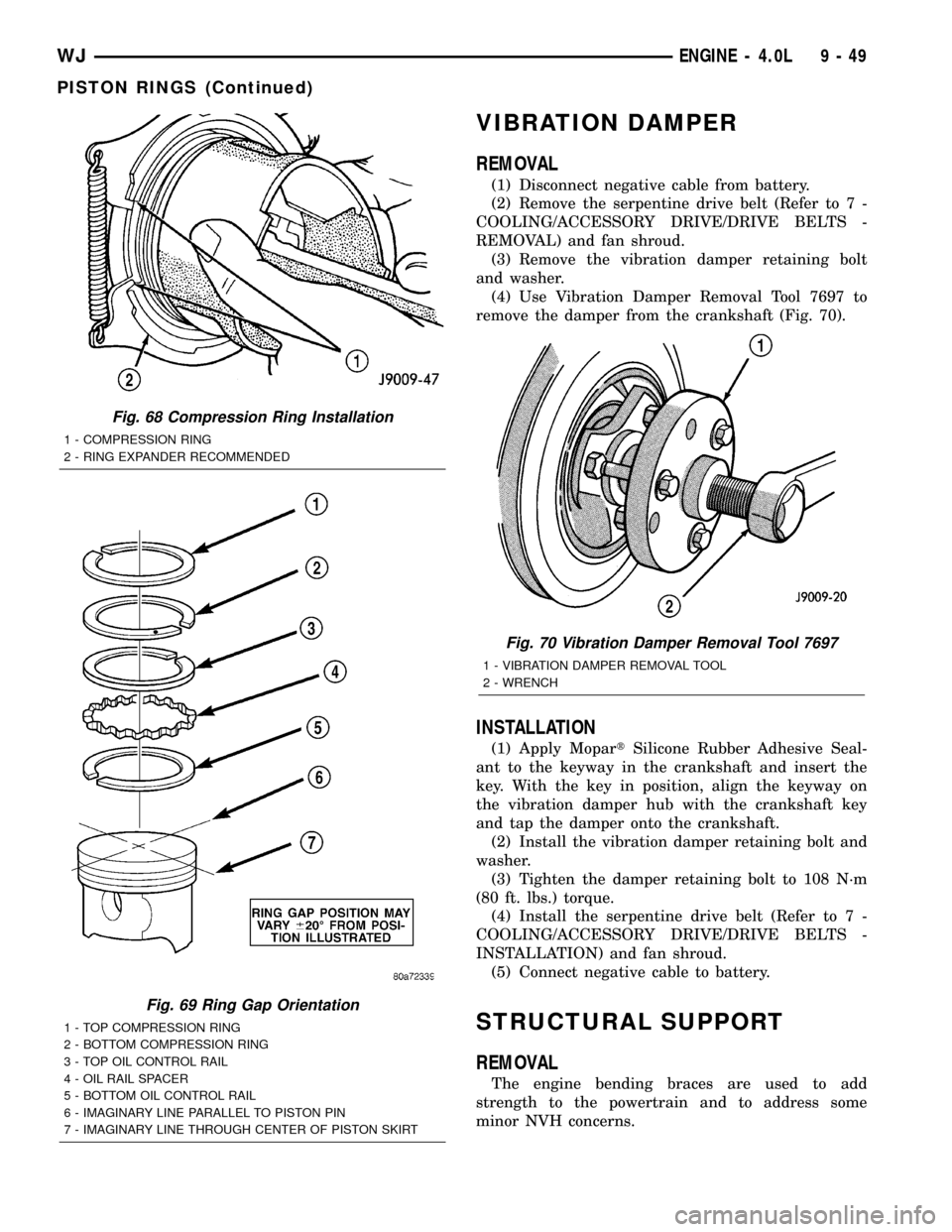
Ring Gap Orientation
²Position the gaps on the piston as shown (Fig.
69).
²Oil spacer - Gap on center line of piston skirt.
²Oil rails - gap 180É apart on centerline of piston
pin bore.
²No. 2 Compression ring - Gap 180É from top oil
rail gap.
²No. 1 Compression ring - Gap 180É from No. 2
compression ring gap.
Fig. 64 Gap Measurement
1 - FEELER GAUGE
Fig. 65 Top Compression ring identification
1 - TOP COMPRESSION RING
Fig. 66 Second Compression Ring Identification
1 - SECOND COMPRESSION RING
2 - CHAMFER
3 - ONE DOT
Fig. 67 Compression Ring Chamfer Location
1 - TOP COMPRESSION RING
2 - SECOND COMPRESSION RING
3 - PISTON
4 - CHAMFER
9 - 48 ENGINE - 4.0LWJ
PISTON RINGS (Continued)
Page 1292 of 2199
VIBRATION DAMPER
REMOVAL
(1) Disconnect negative cable from battery.
(2) Remove the serpentine drive belt (Refer to 7 -
COOLING/ACCESSORY DRIVE/DRIVE BELTS -
REMOVAL) and fan shroud.
(3) Remove the vibration damper retaining bolt
and washer.
(4) Use Vibration Damper Removal Tool 7697 to
remove the damper from the crankshaft (Fig. 70).
INSTALLATION
(1) Apply MopartSilicone Rubber Adhesive Seal-
ant to the keyway in the crankshaft and insert the
key. With the key in position, align the keyway on
the vibration damper hub with the crankshaft key
and tap the damper onto the crankshaft.
(2) Install the vibration damper retaining bolt and
washer.
(3) Tighten the damper retaining bolt to 108 N´m
(80 ft. lbs.) torque.
(4) Install the serpentine drive belt (Refer to 7 -
COOLING/ACCESSORY DRIVE/DRIVE BELTS -
INSTALLATION) and fan shroud.
(5) Connect negative cable to battery.
STRUCTURAL SUPPORT
REMOVAL
The engine bending braces are used to add
strength to the powertrain and to address some
minor NVH concerns.
Fig. 68 Compression Ring Installation
1 - COMPRESSION RING
2 - RING EXPANDER RECOMMENDED
Fig. 69 Ring Gap Orientation
1 - TOP COMPRESSION RING
2 - BOTTOM COMPRESSION RING
3 - TOP OIL CONTROL RAIL
4 - OIL RAIL SPACER
5 - BOTTOM OIL CONTROL RAIL
6 - IMAGINARY LINE PARALLEL TO PISTON PIN
7 - IMAGINARY LINE THROUGH CENTER OF PISTON SKIRT
Fig. 70 Vibration Damper Removal Tool 7697
1 - VIBRATION DAMPER REMOVAL TOOL
2 - WRENCH
WJENGINE - 4.0L 9 - 49
PISTON RINGS (Continued)
Page 1301 of 2199
(3) Install intake manifold on the cylinder head
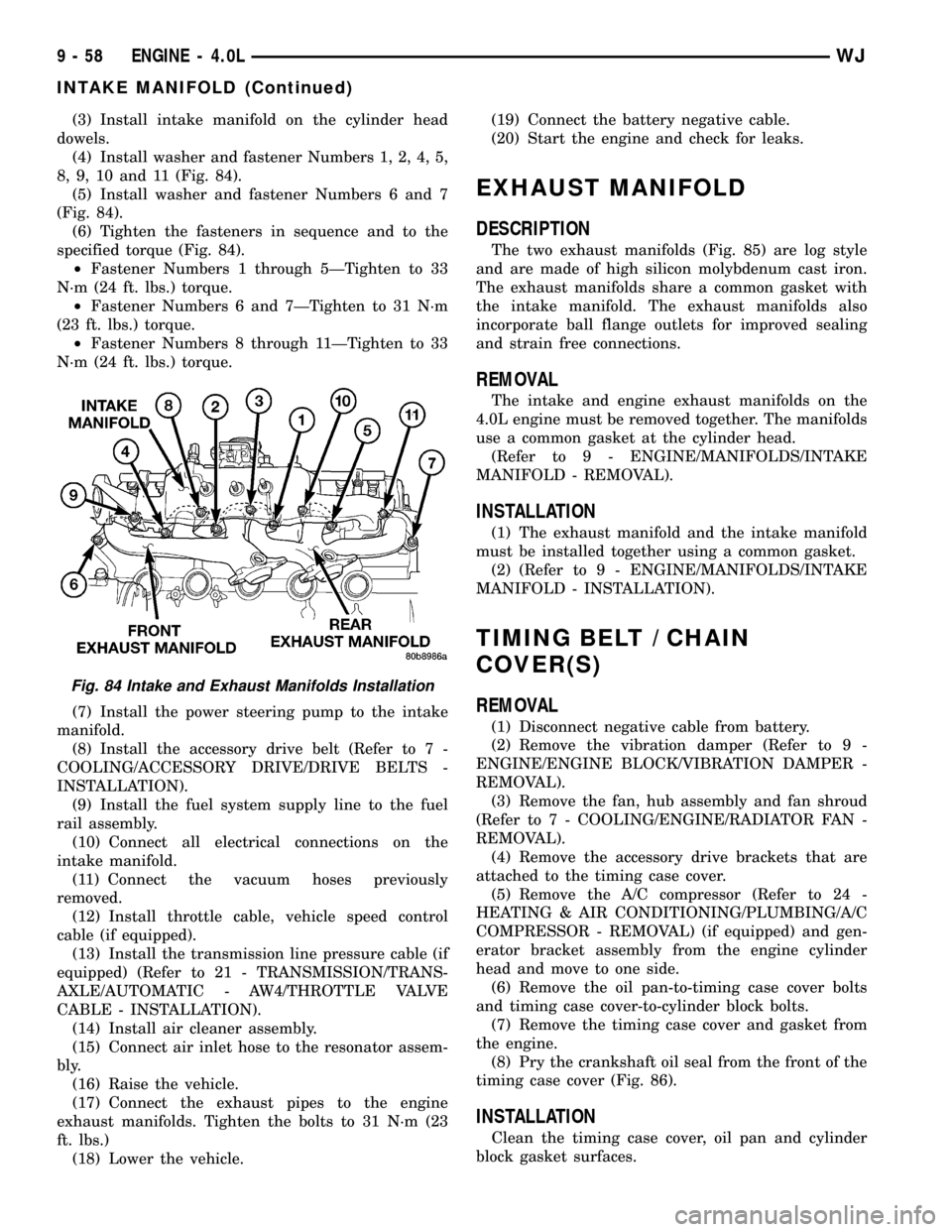
dowels.
(4) Install washer and fastener Numbers 1, 2, 4, 5,
8, 9, 10 and 11 (Fig. 84).
(5) Install washer and fastener Numbers 6 and 7
(Fig. 84).
(6) Tighten the fasteners in sequence and to the
specified torque (Fig. 84).
²Fastener Numbers 1 through 5ÐTighten to 33
N´m (24 ft. lbs.) torque.
²Fastener Numbers 6 and 7ÐTighten to 31 N´m
(23 ft. lbs.) torque.
²Fastener Numbers 8 through 11ÐTighten to 33
N´m (24 ft. lbs.) torque.
(7) Install the power steering pump to the intake
manifold.
(8) Install the accessory drive belt (Refer to 7 -
COOLING/ACCESSORY DRIVE/DRIVE BELTS -
INSTALLATION).
(9) Install the fuel system supply line to the fuel
rail assembly.
(10) Connect all electrical connections on the
intake manifold.
(11) Connect the vacuum hoses previously
removed.
(12) Install throttle cable, vehicle speed control
cable (if equipped).
(13) Install the transmission line pressure cable (if
equipped) (Refer to 21 - TRANSMISSION/TRANS-
AXLE/AUTOMATIC - AW4/THROTTLE VALVE
CABLE - INSTALLATION).
(14) Install air cleaner assembly.
(15) Connect air inlet hose to the resonator assem-
bly.
(16) Raise the vehicle.
(17) Connect the exhaust pipes to the engine
exhaust manifolds. Tighten the bolts to 31 N´m (23
ft. lbs.)
(18) Lower the vehicle.(19) Connect the battery negative cable.
(20) Start the engine and check for leaks.
EXHAUST MANIFOLD
DESCRIPTION
The two exhaust manifolds (Fig. 85) are log style
and are made of high silicon molybdenum cast iron.
The exhaust manifolds share a common gasket with
the intake manifold. The exhaust manifolds also
incorporate ball flange outlets for improved sealing
and strain free connections.
REMOVAL
The intake and engine exhaust manifolds on the
4.0L engine must be removed together. The manifolds
use a common gasket at the cylinder head.
(Refer to 9 - ENGINE/MANIFOLDS/INTAKE
MANIFOLD - REMOVAL).
INSTALLATION
(1) The exhaust manifold and the intake manifold
must be installed together using a common gasket.
(2) (Refer to 9 - ENGINE/MANIFOLDS/INTAKE
MANIFOLD - INSTALLATION).
TIMING BELT / CHAIN
COVER(S)
REMOVAL
(1) Disconnect negative cable from battery.
(2) Remove the vibration damper (Refer to 9 -
ENGINE/ENGINE BLOCK/VIBRATION DAMPER -
REMOVAL).
(3) Remove the fan, hub assembly and fan shroud
(Refer to 7 - COOLING/ENGINE/RADIATOR FAN -
REMOVAL).
(4) Remove the accessory drive brackets that are
attached to the timing case cover.
(5) Remove the A/C compressor (Refer to 24 -
HEATING & AIR CONDITIONING/PLUMBING/A/C
COMPRESSOR - REMOVAL) (if equipped) and gen-
erator bracket assembly from the engine cylinder
head and move to one side.
(6) Remove the oil pan-to-timing case cover bolts
and timing case cover-to-cylinder block bolts.
(7) Remove the timing case cover and gasket from
the engine.
(8) Pry the crankshaft oil seal from the front of the
timing case cover (Fig. 86).
INSTALLATION
Clean the timing case cover, oil pan and cylinder
block gasket surfaces.
Fig. 84 Intake and Exhaust Manifolds Installation
9 - 58 ENGINE - 4.0LWJ
INTAKE MANIFOLD (Continued)
Page 1302 of 2199
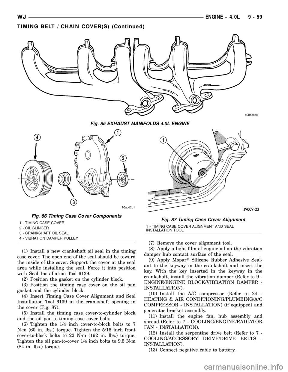
(1) Install a new crankshaft oil seal in the timing
case cover. The open end of the seal should be toward
the inside of the cover. Support the cover at the seal
area while installing the seal. Force it into position
with Seal Installation Tool 6139.
(2) Position the gasket on the cylinder block.
(3) Position the timing case cover on the oil pan
gasket and the cylinder block.
(4) Insert Timing Case Cover Alignment and Seal
Installation Tool 6139 in the crankshaft opening in
the cover (Fig. 87).
(5) Install the timing case cover-to-cylinder block
and the oil pan-to-timing case cover bolts.
(6) Tighten the 1/4 inch cover-to-block bolts to 7
N´m (60 in. lbs.) torque. Tighten the 5/16 inch front
cover-to-block bolts to 22 N´m (192 in. lbs.) torque.
Tighten the oil pan-to-cover 1/4 inch bolts to 9.5 N´m
(84 in. lbs.) torque.(7) Remove the cover alignment tool.
(8) Apply a light film of engine oil on the vibration
damper hub contact surface of the seal.
(9) Apply MopartSilicone Rubber Adhesive Seal-
ant to the keyway in the crankshaft and insert the
key. With the key inserted in the keyway in the
crankshaft, install the vibration damper (Refer to 9 -
ENGINE/ENGINE BLOCK/VIBRATION DAMPER -
INSTALLATION).
(10) Install the A/C compressor (Refer to 24 -
HEATING & AIR CONDITIONING/PLUMBING/A/C
COMPRESSOR - INSTALLATION) (if equipped) and
generator bracket assembly.
(11) Install the engine fan, hub assembly and
shroud (Refer to 7 - COOLING/ENGINE/RADIATOR
FAN - INSTALLATION).
(12) Install the serpentine drive belt (Refer to 7 -
COOLING/ACCESSORY DRIVE/DRIVE BELTS -
INSTALLATION).
(13) Connect negative cable to battery.
Fig. 85 EXHAUST MANIFOLDS 4.0L ENGINE
Fig. 86 Timing Case Cover Components
1 - TIMING CASE COVER
2 - OIL SLINGER
3 - CRANKSHAFT OIL SEAL
4 - VIBRATION DAMPER PULLEYFig. 87 Timing Case Cover Alignment
1 - TIMING CASE COVER ALIGNMENT AND SEAL
INSTALLATION TOOL
WJENGINE - 4.0L 9 - 59
TIMING BELT / CHAIN COVER(S) (Continued)