2003 JEEP GRAND CHEROKEE run flat
[x] Cancel search: run flatPage 48 of 2199
(10) Start the engine and re-check for vibration. If
there is little or no change in vibration, move the
clamp to one of the other three positions. Repeat the
vibration test.
(11) If there is no difference in vibration at the
other positions, the source of the vibration may not
be propeller shaft.
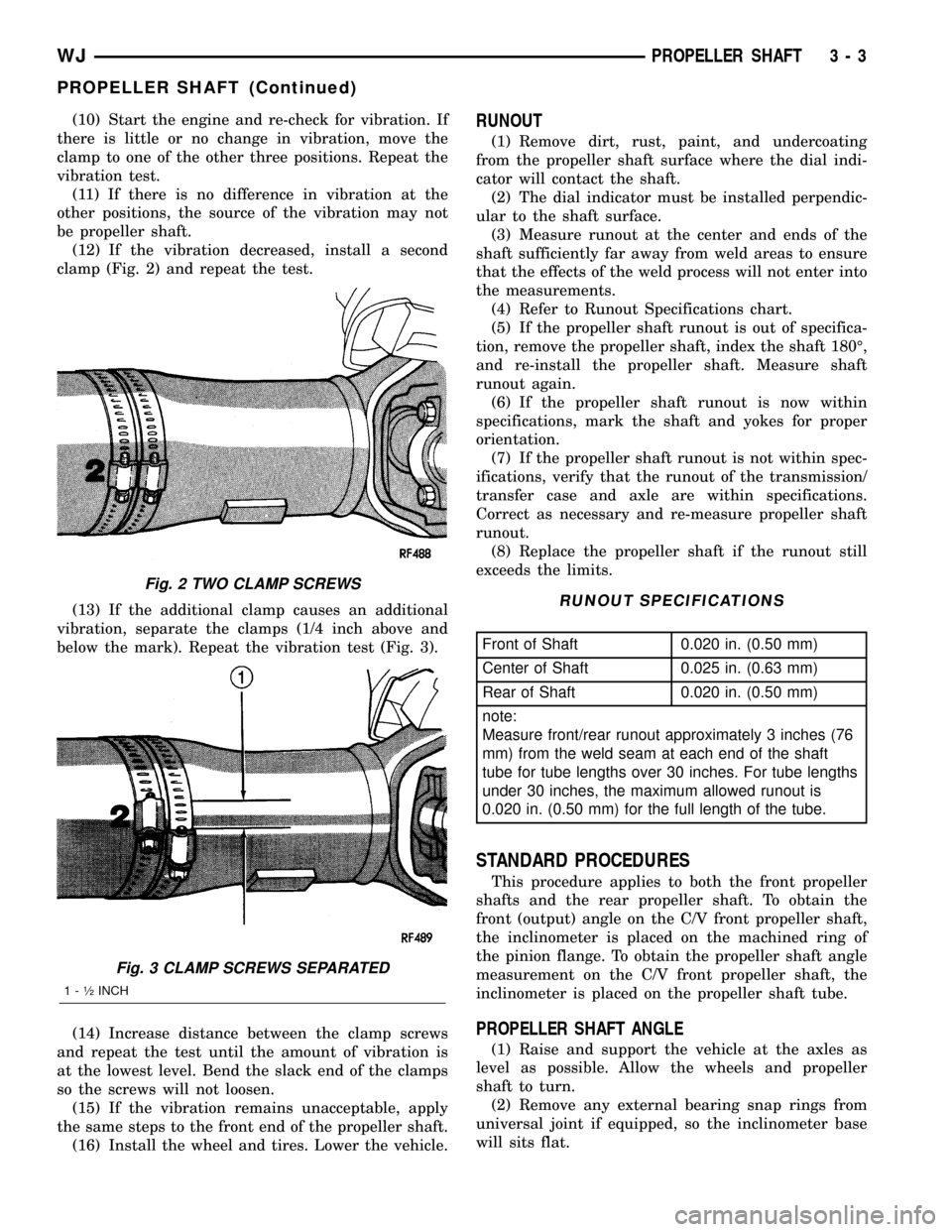
(12) If the vibration decreased, install a second
clamp (Fig. 2) and repeat the test.
(13) If the additional clamp causes an additional
vibration, separate the clamps (1/4 inch above and
below the mark). Repeat the vibration test (Fig. 3).
(14) Increase distance between the clamp screws
and repeat the test until the amount of vibration is
at the lowest level. Bend the slack end of the clamps
so the screws will not loosen.
(15) If the vibration remains unacceptable, apply
the same steps to the front end of the propeller shaft.
(16) Install the wheel and tires. Lower the vehicle.RUNOUT
(1) Remove dirt, rust, paint, and undercoating
from the propeller shaft surface where the dial indi-
cator will contact the shaft.
(2) The dial indicator must be installed perpendic-
ular to the shaft surface.
(3) Measure runout at the center and ends of the
shaft sufficiently far away from weld areas to ensure
that the effects of the weld process will not enter into
the measurements.
(4) Refer to Runout Specifications chart.
(5) If the propeller shaft runout is out of specifica-
tion, remove the propeller shaft, index the shaft 180É,
and re-install the propeller shaft. Measure shaft
runout again.
(6) If the propeller shaft runout is now within
specifications, mark the shaft and yokes for proper
orientation.
(7) If the propeller shaft runout is not within spec-
ifications, verify that the runout of the transmission/
transfer case and axle are within specifications.
Correct as necessary and re-measure propeller shaft
runout.
(8) Replace the propeller shaft if the runout still
exceeds the limits.
RUNOUT SPECIFICATIONS
Front of Shaft 0.020 in. (0.50 mm)
Center of Shaft 0.025 in. (0.63 mm)
Rear of Shaft 0.020 in. (0.50 mm)
note:
Measure front/rear runout approximately 3 inches (76
mm) from the weld seam at each end of the shaft
tube for tube lengths over 30 inches. For tube lengths
under 30 inches, the maximum allowed runout is
0.020 in. (0.50 mm) for the full length of the tube.
STANDARD PROCEDURES
This procedure applies to both the front propeller
shafts and the rear propeller shaft. To obtain the
front (output) angle on the C/V front propeller shaft,
the inclinometer is placed on the machined ring of
the pinion flange. To obtain the propeller shaft angle
measurement on the C/V front propeller shaft, the
inclinometer is placed on the propeller shaft tube.
PROPELLER SHAFT ANGLE
(1) Raise and support the vehicle at the axles as
level as possible. Allow the wheels and propeller
shaft to turn.
(2) Remove any external bearing snap rings from
universal joint if equipped, so the inclinometer base
will sits flat.
Fig. 2 TWO CLAMP SCREWS
Fig. 3 CLAMP SCREWS SEPARATED
1 - ó INCH
WJPROPELLER SHAFT 3 - 3
PROPELLER SHAFT (Continued)
Page 207 of 2199
Measure rotor thickness a minimum of six points
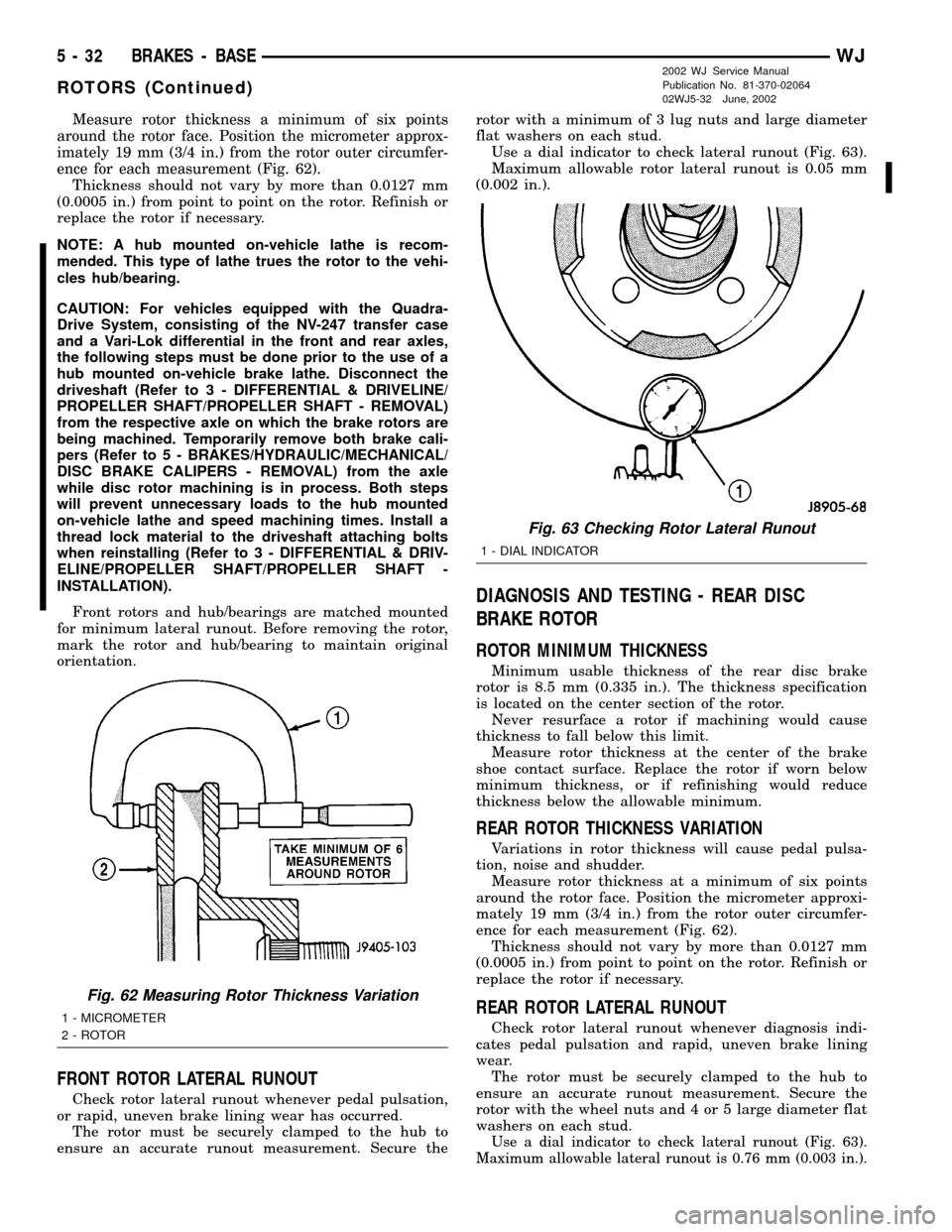
around the rotor face. Position the micrometer approx-
imately 19 mm (3/4 in.) from the rotor outer circumfer-
ence for each measurement (Fig. 62).
Thickness should not vary by more than 0.0127 mm
(0.0005 in.) from point to point on the rotor. Refinish or
replace the rotor if necessary.
NOTE: A hub mounted on-vehicle lathe is recom-
mended. This type of lathe trues the rotor to the vehi-
cles hub/bearing.
CAUTION: For vehicles equipped with the Quadra-
Drive System, consisting of the NV-247 transfer case
and a Vari-Lok differential in the front and rear axles,
the following steps must be done prior to the use of a
hub mounted on-vehicle brake lathe. Disconnect the
driveshaft (Refer to 3 - DIFFERENTIAL & DRIVELINE/
PROPELLER SHAFT/PROPELLER SHAFT - REMOVAL)
from the respective axle on which the brake rotors are
being machined. Temporarily remove both brake cali-
pers (Refer to 5 - BRAKES/HYDRAULIC/MECHANICAL/
DISC BRAKE CALIPERS - REMOVAL) from the axle
while disc rotor machining is in process. Both steps
will prevent unnecessary loads to the hub mounted
on-vehicle lathe and speed machining times. Install a
thread lock material to the driveshaft attaching bolts
when reinstalling (Refer to 3 - DIFFERENTIAL & DRIV-
ELINE/PROPELLER SHAFT/PROPELLER SHAFT -
INSTALLATION).
Front rotors and hub/bearings are matched mounted
for minimum lateral runout. Before removing the rotor,
mark the rotor and hub/bearing to maintain original
orientation.
FRONT ROTOR LATERAL RUNOUT
Check rotor lateral runout whenever pedal pulsation,
or rapid, uneven brake lining wear has occurred.
The rotor must be securely clamped to the hub to
ensure an accurate runout measurement. Secure therotor with a minimum of 3 lug nuts and large diameter
flat washers on each stud.
Use a dial indicator to check lateral runout (Fig. 63).
Maximum allowable rotor lateral runout is 0.05 mm
(0.002 in.).
DIAGNOSIS AND TESTING - REAR DISC
BRAKE ROTOR
ROTOR MINIMUM THICKNESS
Minimum usable thickness of the rear disc brake
rotor is 8.5 mm (0.335 in.). The thickness specification
is located on the center section of the rotor.
Never resurface a rotor if machining would cause
thickness to fall below this limit.
Measure rotor thickness at the center of the brake
shoe contact surface. Replace the rotor if worn below
minimum thickness, or if refinishing would reduce
thickness below the allowable minimum.
REAR ROTOR THICKNESS VARIATION
Variations in rotor thickness will cause pedal pulsa-
tion, noise and shudder.
Measure rotor thickness at a minimum of six points
around the rotor face. Position the micrometer approxi-
mately 19 mm (3/4 in.) from the rotor outer circumfer-
ence for each measurement (Fig. 62).
Thickness should not vary by more than 0.0127 mm
(0.0005 in.) from point to point on the rotor. Refinish or
replace the rotor if necessary.
REAR ROTOR LATERAL RUNOUT
Check rotor lateral runout whenever diagnosis indi-
cates pedal pulsation and rapid, uneven brake lining
wear.
The rotor must be securely clamped to the hub to
ensure an accurate runout measurement. Secure the
rotor with the wheel nuts and 4 or 5 large diameter flat
washers on each stud.
Use a dial indicator to check lateral runout (Fig. 63).
Maximum allowable lateral runout is 0.76 mm (0.003 in.).
Fig. 62 Measuring Rotor Thickness Variation
1 - MICROMETER
2 - ROTOR
Fig. 63 Checking Rotor Lateral Runout
1 - DIAL INDICATOR
5 - 32 BRAKES - BASEWJ
ROTORS (Continued)
2002 WJ Service Manual
Publication No. 81-370-02064
02WJ5-32 June, 2002
Page 545 of 2199

WARNING: IF YOU EXPERIENCE SKIN IRRITATION
DURING CLEANUP, RUN COOL WATER OVER THE
AFFECTED AREA. ALSO, IF YOU EXPERIENCE IRRITA-
TION OF THE NOSE OR THROAT, EXIT THE VEHICLE
FOR FRESH AIR UNTIL THE IRRITATION CEASES. IF
IRRITATION CONTINUES, SEE A PHYSICIAN.
(1) Begin the cleanup by using a vacuum cleaner
to remove any residual powder from the vehicle inte-
rior. Clean from outside the vehicle and work your
way inside, so that you avoid kneeling or sitting on a
non-cleaned area.
(2) Be certain to vacuum the heater and air condi-
tioning outlets as well (Fig. 4). Run the heater and
air conditioner blower on the lowest speed setting
and vacuum any powder expelled from the outlets.
CAUTION: Deployed front airbags having two initia-
tors (squibs) in the airbag inflator may or may not
have live pyrotechnic material within the inflator. Do
not dispose of these airbags unless you are sure of
complete deployment. Refer to AIRBAG SQUIB STA-
TUS . Refer to the Hazardous Substance Control
System for proper disposal procedures. Dispose of
all non-deployed and deployed airbags in a manner
consistent with state, provincial, local, and federal
regulations.
(3) Next, remove the deployed supplemental
restraints from the vehicle. Refer to the appropriate
service removal procedures.
(4) You may need to vacuum the interior of the
vehicle a second time to recover all of the powder.
STANDARD PROCEDURE - VERIFICATION TEST
The following procedure should be performed using
a DRBIIItscan tool to verify proper supplemental
restraint system operation following the service or
replacement of any supplemental restraint system
component.WARNING: ON VEHICLES EQUIPPED WITH AIR-
BAGS, DISABLE THE SUPPLEMENTAL RESTRAINT
SYSTEM BEFORE ATTEMPTING ANY STEERING
WHEEL, STEERING COLUMN, DRIVER AIRBAG,
PASSENGER AIRBAG, FRONT IMPACT SENSOR,
SIDE IMPACT SENSOR, SIDE CURTAIN AIRBAG, OR
INSTRUMENT PANEL COMPONENT DIAGNOSIS OR
SERVICE. DISCONNECT AND ISOLATE THE BAT-
TERY NEGATIVE (GROUND) CABLE, THEN WAIT
TWO MINUTES FOR THE SYSTEM CAPACITOR TO
DISCHARGE BEFORE PERFORMING FURTHER
DIAGNOSIS OR SERVICE. THIS IS THE ONLY SURE
WAY TO DISABLE THE SUPPLEMENTAL
RESTRAINT SYSTEM. FAILURE TO TAKE THE
PROPER PRECAUTIONS COULD RESULT IN ACCI-
DENTAL AIRBAG DEPLOYMENT AND POSSIBLE
PERSONAL INJURY.
(1) During the following test, the battery negative
cable remains disconnected and isolated, as it was
during the airbag component removal and installa-
tion procedures.
(2) Be certain that the DRBIIItscan tool contains
the latest version of the proper DRBIIItsoftware.
Connect the DRBIIItto the 16-way Data Link Con-
nector (DLC). The DLC is located on the driver side
lower edge of the instrument panel, outboard of the
steering column (Fig. 5).
(3) Turn the ignition switch to the On position and
exit the vehicle with the DRBIIItscan tool.
Fig. 4 Vacuum Heater and A/C Outlets - Typical
Fig. 5 16-Way Data Link Connector - Typical
1 - 16±WAY DATA LINK CONNECTOR
2 - BOTTOM OF INSTRUMENT PANEL
8O - 8 RESTRAINTSWJ
RESTRAINTS (Continued)
Page 1259 of 2199
DESCRIPTION SPECIFICATION
Valve Stem-to-Guide 0.025 to 0.076 mm
Clearance (0.001 to 0.003 in.)
Valve Seat Angle
Intake 44.5É
Exhaust 44.5É
Valve Seat Width 1.02 to 1.52 mm
(0.040 to 0.060 in.)
Valve Seat Runout 0.064 mm (0.0025 in.)
Flatness 0.03 mm per 25 mm
(0.001 in. per 1 in.)
0.05 mm per 152 mm
(0.002 in. per 6 in.)
Flatness Max. 0.20 mm - max. for total
length
(0.008 in. max. for total
length)
ROCKER ARMS, PUSH RODS & TAPPETS
Rocker Arm Ratio 1.6:1
Push Rod Length 244.856 to 245.364 mm
(Pink) (9.640 to 9.660 in.)
Push Rod Diameter 7.92 to 8.00 mm
(0.312 to 0.315 in.)
Hydraulic Tappet
Diameter22.962 to 22.974 mm
(0.904 to 0.9045 in.)
Tappet-to-Bore Clearance 0.025 to 0.063 mm
(0.001 to 0.0025 in.)
VA LV E S
Valve Length (Overall)
Intake 122.479 to 122.860 mm
(4.822 to 4.837 in.)
Exhaust 122.860 to 123.241 mm
(4.837 to 4.852 in.)
Valve Stem Diameter 7.899 to 7.925 mm
(0.311 to 0.312 in.)
Stem-to-Guide Clearance 0.025 to 0.076 mm
(0.001 to 0.003 in.)DESCRIPTION SPECIFICATION
Valve Head Diameter
Intake 48.387 to 48.641 mm
(1.905 to 1.915 in.)
Exhaust 37.973 to 38.227 mm
(1.495 to 1.505 in.)
Valve Face Angle
Intake 46.5É
Exhaust 46.5É
Tip Refinishing (Max.
Allowable)0.25 mm (0.010 in.)
VALVE SPRINGS
Free Length (Approx.) 47.65 mm (1.876 in.)
Spring Load
Valve Closed 316 to 351 N @ 41.656
mm
(71 to 79 lbf. @ 1.64 in.)
Valve Open 898.6 to 969.7 N @
30.89 mm
(202 to 218 lbf @ 1.216
in.)
Inside Diameter 21.0 mm to 21.51 mm
(0.827 to 0.847 in.)
Installed Height 41.656 mm (1.64 in.)
PISTONS
Weight (Less Pin) 417 to 429 grams
(14.7 to 15.1 oz.)
Piston Pin Bore
(Centerline40.61 to 40.72 mm
to Piston Top) (1.599 to 1.603 in.)
Piston-to-Bore Clearance 0.018 to 0.038 mm
(0.0008 to 0.0015 in.)
Ring Gap Clearance
Top Compression Ring 0.229 to 0.610 mm
(0.0090 to 0.0240 in.)
2nd Compression Ring 0.483 to 0.965 mm
(0.0190 to 0.0380 in.)
Oil Control Steel Rails 0.254 to 1.500 mm
(0.010 to 0.060 in.)
9 - 16 ENGINE - 4.0LWJ
ENGINE - 4.0L (Continued)
Page 1319 of 2199
DESCRIPTION SPECIFICATION
Exhaust 36.87 - 37.13 mm
1.4516 - 1.4618 in.)
Length (Overall)
Intake 113.45 - 114.21 mm
(4.4666 - 4.4965)
Exhaust 114.92 - 115.68 mm
(4.5244 - 4.5543 in.)
Stem Diameter
Intake 6.931 - 6.957 mm
(0.2729 - 0.2739 in.)
Exhaust 6.902 - 6.928 mm
(0.2717 - 0.2728 in.)
Stem - to - Guide
Clearance
Intake .018 - .069 mm
(0.0008 - 0.0028 in.)
Exhaust .047 - .098 mm
(0.0019 - 0.0039 in.)
Max. Allowable Stem -
to -
Guide Clearance
(Rocking
Method)
Intake 0.069 mm (0.0028 in.)
Exhaust 0.098 mm (0.0039 in.)
Valve Lift (Zero Lash)
Intake 11.25 mm (0.443 in.)
Exhaust 10.90 mm (0.4292 in.)
VALVE SPRING
Free Length (Approx)
Intake and Exhaust 48.6 mm (1.9134 in.)
Spring Force (Valve
Closed)
Intake and Exhaust 315.5 - 352.5 N @ 40.89
mm
(70.92722 - 79.24515 lbs.
@ 1.6099 in.)DESCRIPTION SPECIFICATION
Spring Force (Valve
Open)
Intake and Exhaust 786.0 - 860.0 N @ 29.64
mm
176.6998 - 193.3357 lbs.
@ 1.167 in.)
Number of Coils
Intake and Exhaust 6.69
Wire Diameter
Intake and Exhaust 4.2799 - 4.3561 mm
(0.1685 - 0.1715 in.)
Installed Height (Spring
Seat to Bottom of
Retainer)
Nominal
Intake 40.97 mm (1.613 in.)
Exhaust 40.81 mm (1.606 in.)
CYLINDER HEAD
Gasket Thickness
(Compressed) .7 mm (0.0276 in.)
Valve Seat Angle 44.5É - 45.0É
Valve Seat Runout (MAX) 0.051 mm (0.002 in.)
Valve Seat Width
Intake 1.75 - 2.36 mm
(0.0698 - 0.0928 in.)
Exhaust 1.71 - 2.32 mm
(0.0673 - 0.0911 in.)
Guide Bore Diameter
(Std.)6.975 - 7.00 mm
(0.2747 - 0.2756 in.)
Cylinder Head Warpage
(Flatness) 0.0508 mm (0.002 in.)
OIL PUMP
Clearance Over Rotors /
End Face (MAX).035 - .095 mm
(0.0014 - 0.0038 in.)
Cover Out - of -Flat
(MAX).025 mm (0.001 in.)
Inner and Outer Rotor
Thickness 12.02 mm (0.4731 in.)
9 - 76 ENGINE - 4.7LWJ
ENGINE - 4.7L (Continued)
Page 1322 of 2199
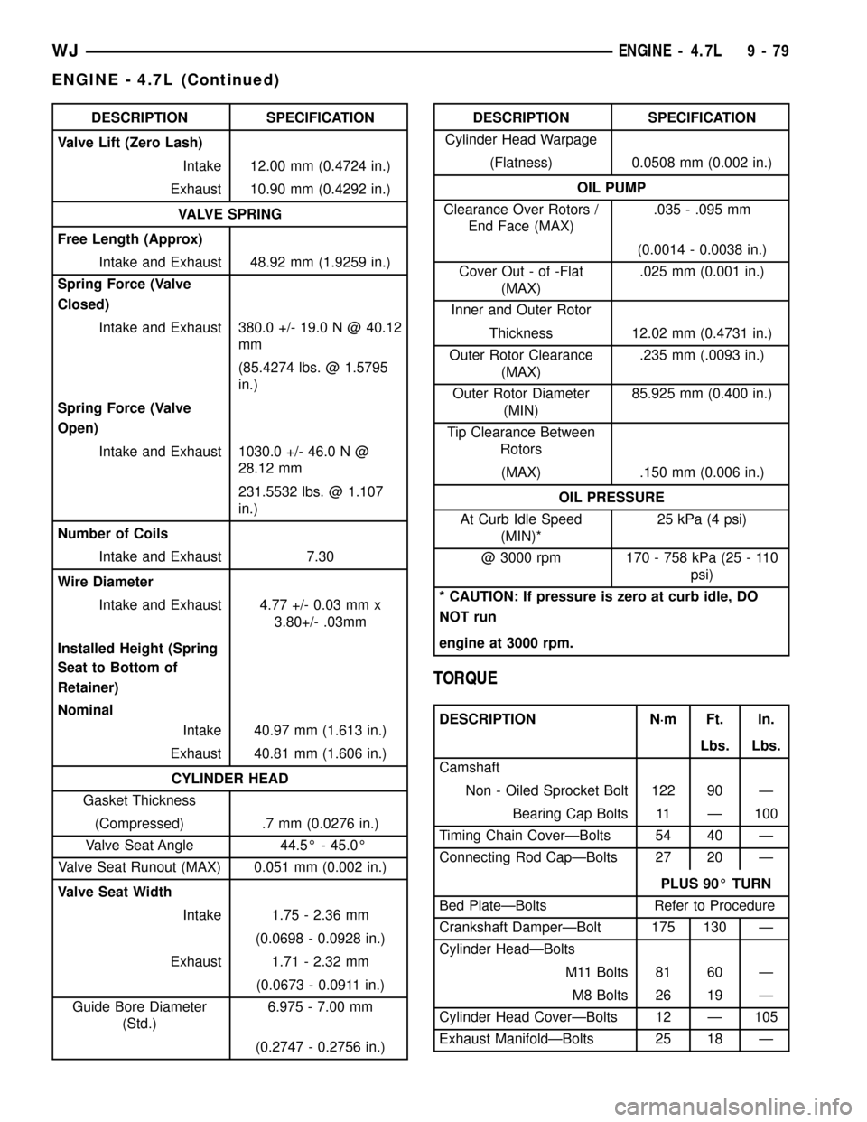
DESCRIPTION SPECIFICATION
Valve Lift (Zero Lash)
Intake 12.00 mm (0.4724 in.)
Exhaust 10.90 mm (0.4292 in.)
VALVE SPRING
Free Length (Approx)
Intake and Exhaust 48.92 mm (1.9259 in.)
Spring Force (Valve
Closed)
Intake and Exhaust 380.0 +/- 19.0 N @ 40.12
mm
(85.4274 lbs. @ 1.5795
in.)
Spring Force (Valve
Open)
Intake and Exhaust 1030.0 +/- 46.0 N @
28.12 mm
231.5532 lbs. @ 1.107
in.)
Number of Coils
Intake and Exhaust 7.30
Wire Diameter
Intake and Exhaust 4.77 +/- 0.03 mm x
3.80+/- .03mm
Installed Height (Spring
Seat to Bottom of
Retainer)
Nominal
Intake 40.97 mm (1.613 in.)
Exhaust 40.81 mm (1.606 in.)
CYLINDER HEAD
Gasket Thickness
(Compressed) .7 mm (0.0276 in.)
Valve Seat Angle 44.5É - 45.0É
Valve Seat Runout (MAX) 0.051 mm (0.002 in.)
Valve Seat Width
Intake 1.75 - 2.36 mm
(0.0698 - 0.0928 in.)
Exhaust 1.71 - 2.32 mm
(0.0673 - 0.0911 in.)
Guide Bore Diameter
(Std.)6.975 - 7.00 mm
(0.2747 - 0.2756 in.)DESCRIPTION SPECIFICATION
Cylinder Head Warpage
(Flatness) 0.0508 mm (0.002 in.)
OIL PUMP
Clearance Over Rotors /
End Face (MAX).035 - .095 mm
(0.0014 - 0.0038 in.)
Cover Out - of -Flat
(MAX).025 mm (0.001 in.)
Inner and Outer Rotor
Thickness 12.02 mm (0.4731 in.)
Outer Rotor Clearance
(MAX).235 mm (.0093 in.)
Outer Rotor Diameter
(MIN)85.925 mm (0.400 in.)
Tip Clearance Between
Rotors
(MAX) .150 mm (0.006 in.)
OIL PRESSURE
At Curb Idle Speed
(MIN)*25 kPa (4 psi)
@ 3000 rpm 170 - 758 kPa (25 - 110
psi)
* CAUTION: If pressure is zero at curb idle, DO
NOT run
engine at 3000 rpm.
TORQUE
DESCRIPTION N´m Ft. In.
Lbs. Lbs.
Camshaft
Non - Oiled Sprocket Bolt 122 90 Ð
Bearing Cap Bolts 11 Ð 100
Timing Chain CoverÐBolts 54 40 Ð
Connecting Rod CapÐBolts 27 20 Ð
PLUS 90É TURN
Bed PlateÐBolts Refer to Procedure
Crankshaft DamperÐBolt 175 130 Ð
Cylinder HeadÐBolts
M11 Bolts 81 60 Ð
M8 Bolts 26 19 Ð
Cylinder Head CoverÐBolts 12 Ð 105
Exhaust ManifoldÐBolts 25 18 Ð
WJENGINE - 4.7L 9 - 79
ENGINE - 4.7L (Continued)
Page 1711 of 2199
(15) Using a feeler gauge through the opening in
the rear of the transmission case, measure the 2C
clutch pack clearance between the 2C reaction plate
and the transmission case at four different points.
The average of these measurements is the 2C clutch
pack clearance. The correct clutch clearance is 0.455-
1.335 mm (0.018-0.053 in.). The reaction plate is not
selective. If the clutch pack clearance is not within
specification, the reaction plate, all the friction discs,
and steels must be replaced.
(16) Remove the 4C retainer/bulkhead and all of
the 2C clutch components from the transmission
case.
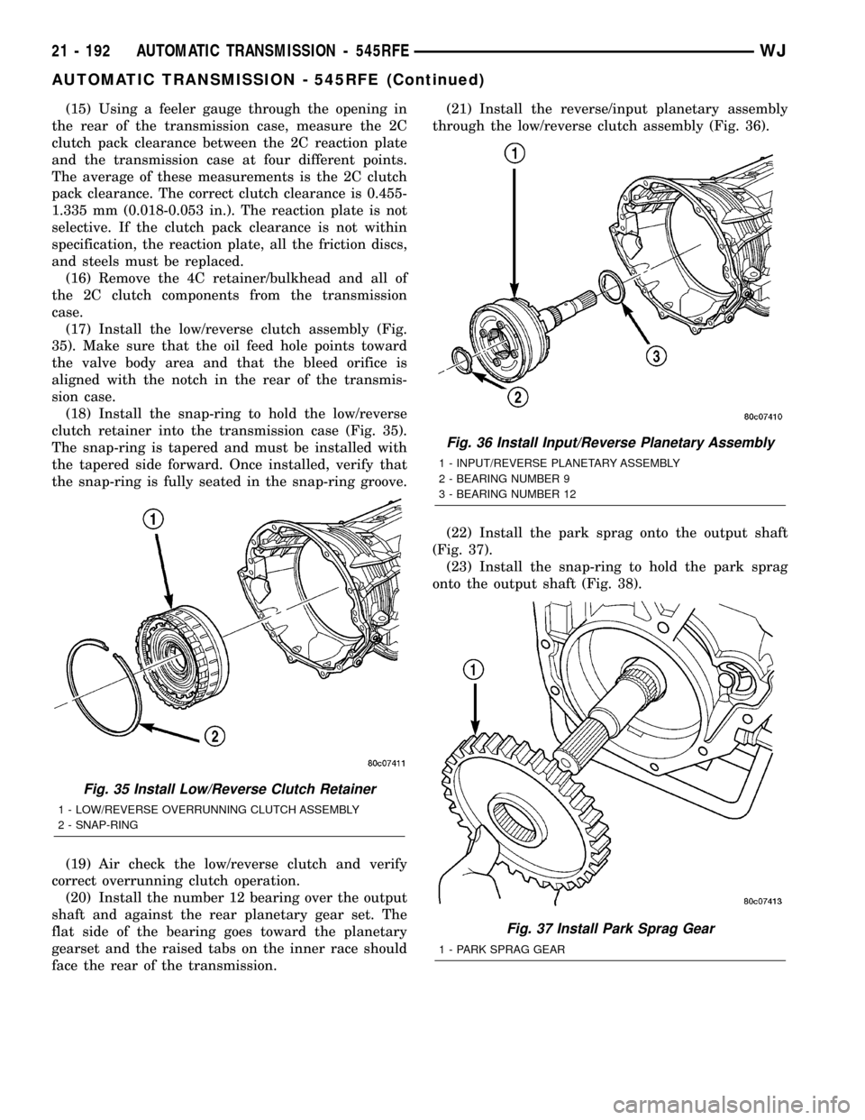
(17) Install the low/reverse clutch assembly (Fig.
35). Make sure that the oil feed hole points toward
the valve body area and that the bleed orifice is
aligned with the notch in the rear of the transmis-
sion case.
(18) Install the snap-ring to hold the low/reverse
clutch retainer into the transmission case (Fig. 35).
The snap-ring is tapered and must be installed with
the tapered side forward. Once installed, verify that
the snap-ring is fully seated in the snap-ring groove.
(19) Air check the low/reverse clutch and verify
correct overrunning clutch operation.
(20) Install the number 12 bearing over the output
shaft and against the rear planetary gear set. The
flat side of the bearing goes toward the planetary
gearset and the raised tabs on the inner race should
face the rear of the transmission.(21) Install the reverse/input planetary assembly
through the low/reverse clutch assembly (Fig. 36).
(22) Install the park sprag onto the output shaft
(Fig. 37).
(23) Install the snap-ring to hold the park sprag
onto the output shaft (Fig. 38).
Fig. 35 Install Low/Reverse Clutch Retainer
1 - LOW/REVERSE OVERRUNNING CLUTCH ASSEMBLY
2 - SNAP-RING
Fig. 36 Install Input/Reverse Planetary Assembly
1 - INPUT/REVERSE PLANETARY ASSEMBLY
2 - BEARING NUMBER 9
3 - BEARING NUMBER 12
Fig. 37 Install Park Sprag Gear
1 - PARK SPRAG GEAR
21 - 192 AUTOMATIC TRANSMISSION - 545RFEWJ
AUTOMATIC TRANSMISSION - 545RFE (Continued)
Page 1765 of 2199
LOW/REVERSE CLUTCH
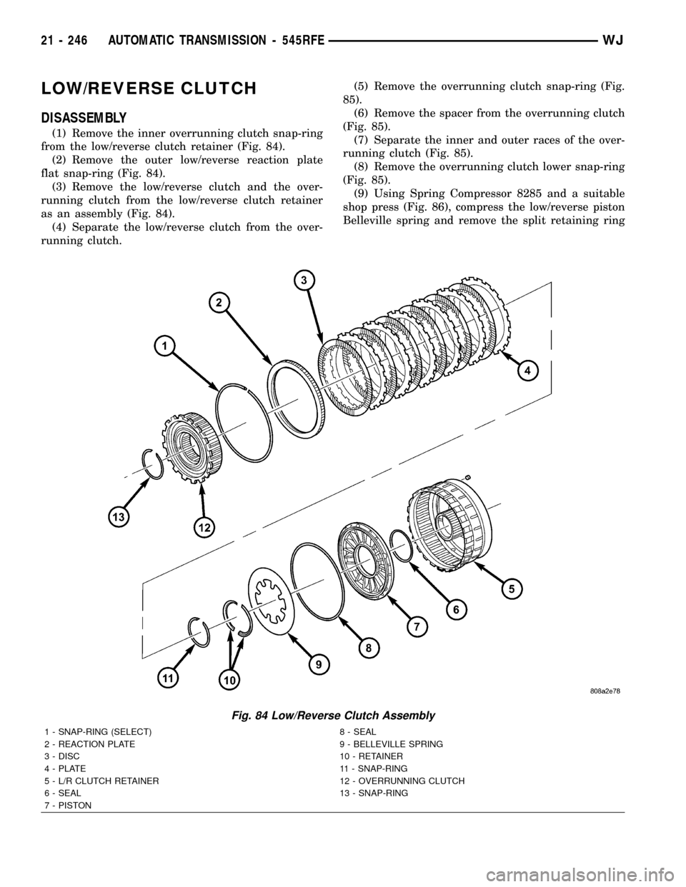
DISASSEMBLY
(1) Remove the inner overrunning clutch snap-ring
from the low/reverse clutch retainer (Fig. 84).
(2) Remove the outer low/reverse reaction plate
flat snap-ring (Fig. 84).
(3) Remove the low/reverse clutch and the over-
running clutch from the low/reverse clutch retainer
as an assembly (Fig. 84).
(4) Separate the low/reverse clutch from the over-
running clutch.(5) Remove the overrunning clutch snap-ring (Fig.
85).
(6) Remove the spacer from the overrunning clutch
(Fig. 85).
(7) Separate the inner and outer races of the over-
running clutch (Fig. 85).
(8) Remove the overrunning clutch lower snap-ring
(Fig. 85).
(9) Using Spring Compressor 8285 and a suitable
shop press (Fig. 86), compress the low/reverse piston
Belleville spring and remove the split retaining ring
Fig. 84 Low/Reverse Clutch Assembly
1 - SNAP-RING (SELECT) 8 - SEAL
2 - REACTION PLATE 9 - BELLEVILLE SPRING
3 - DISC 10 - RETAINER
4 - PLATE 11 - SNAP-RING
5 - L/R CLUTCH RETAINER 12 - OVERRUNNING CLUTCH
6 - SEAL 13 - SNAP-RING
7 - PISTON
21 - 246 AUTOMATIC TRANSMISSION - 545RFEWJ