2003 JEEP GRAND CHEROKEE Engine harness
[x] Cancel search: Engine harnessPage 1315 of 2199

(13) Disconnect the engine block heater power
cable from the block heater.
(14) Lower vehicle.
(15) Remove throttle body resonator assembly and
inlet hose.
(16) Disconnect throttle and speed control cables.
(17) Disconnect tube from both the left and right
side crankcase breathers, then remove the breathers
(Fig. 5).
(18) Discharge A/C system (Refer to 24 - HEAT-
ING & AIR CONDITIONING/PLUMBING - STAN-
DARD PROCEDURE).(19) Remove radiator fan (Refer to 7 - COOLING/
ENGINE/RADIATOR FAN - REMOVAL) and acces-
sory drive belt (Refer to 7 - COOLING/ACCESSORY
DRIVE/DRIVE BELTS - REMOVAL).
(20) Remove A/C compressor (Refer to 24 - HEAT-
ING & AIR CONDITIONING/PLUMBING/A/C COM-
PRESSOR - REMOVAL).
(21) Disconnect transmission oil cooler lines at the
radiator.
(22) Disconnect radiator lower hose at the thermo-
stat housing.
(23) Remove A/C condenser (Refer to 24 - HEAT-
ING & AIR CONDITIONING/PLUMBING/A/C CON-
DENSER - REMOVAL).
(24) Remove radiator (Refer to 7 - COOLING/EN-
GINE/RADIATOR - REMOVAL).
(25) Remove generator (Refer to 8 - ELECTRICAL/
CHARGING/GENERATOR - REMOVAL).
(26) Disconnect the two heater hoses from the tim-
ing chain cover.
(27) Disconnect engine harness at the following
points :
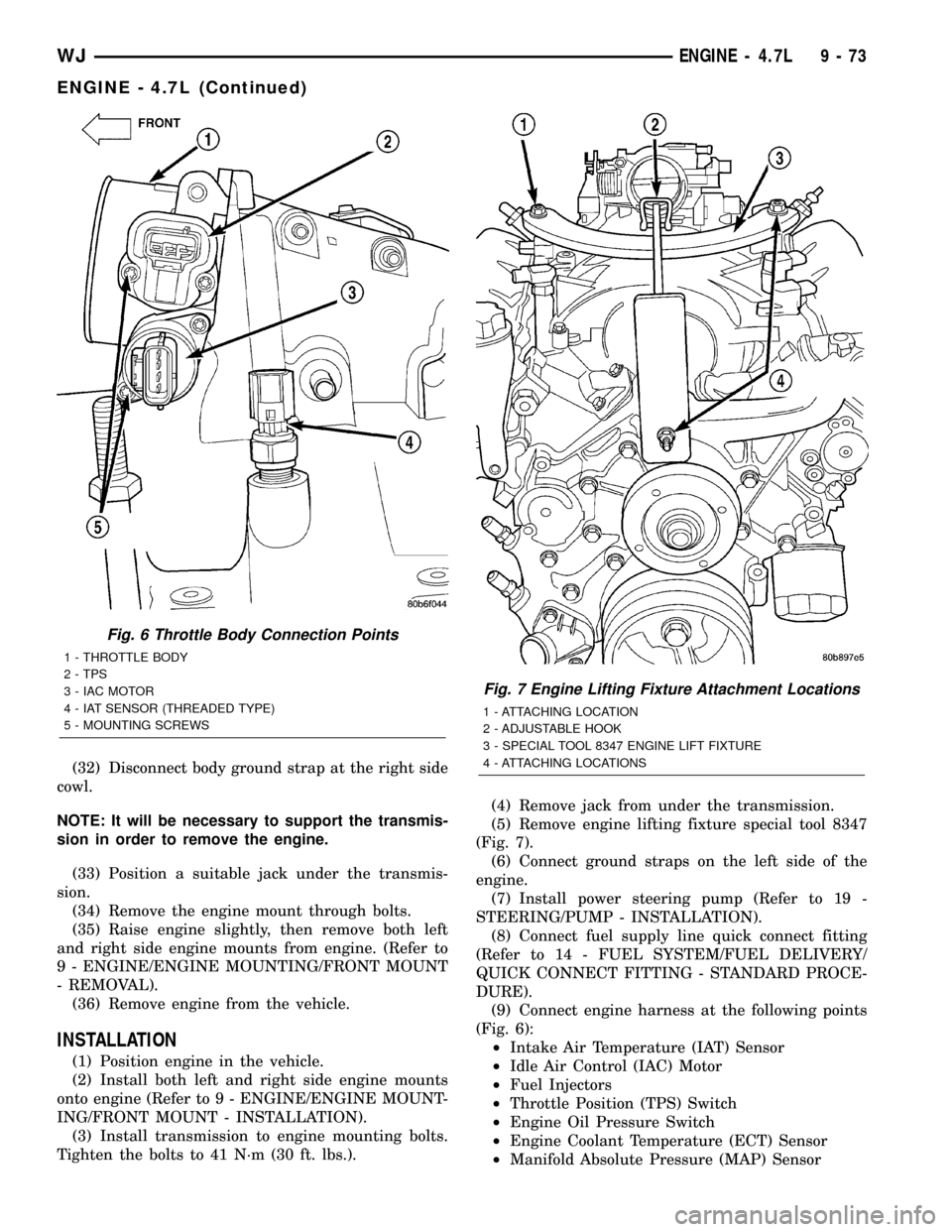
²Intake air temperature (IAT) sensor (Fig. 6)
²Fuel Injectors
²Throttle Position (TPS) Switch
²Idle Air Control (IAC) Motor
²Engine Oil Pressure Switch
²Engine Coolant Temperature (ECT) Sensor
²Manifold absolute pressure (MAP) Sensor
²Camshaft Position (CMP) Sensor
²Coil Over Plugs
(28) Release fuel rail pressure (Refer to 14 - FUEL
SYSTEM/FUEL DELIVERY - STANDARD PROCE-
DURE) then disconnect the fuel supply quick connect
fitting at the fuel rail (Refer to 14 - FUEL SYSTEM/
FUEL DELIVERY/QUICK CONNECT FITTING -
STANDARD PROCEDURE).
(29) Remove power steering pump and position out
of the way.
(30) Disconnect ground straps from the left side of
the engine.
(31) Install Engine Lifting Fixture Special Tool
8347 (Fig. 7)following these steps.
²Holding the lifting fixture at a slight angle, slide
the large bore in the front plate over the hex portion
of the lifting stud.
²Position the two remaining fixture arms onto
the two lifting studs in the cylinder heads.
²Pull foward and upward on the lifting fixture so
that the lifting stud rest in the slotted area below the
large bore.
²Secure the lifting fixture to the three studs
using three 7/16 ± 14 N/C locknuts.
²Make sure the lifting loop in the lifting fixture is
in the last hole (closest to the throttle body) to min-
imize the angle of engine during removal.
Fig. 4 Crankshaft Position Sensor
1 - CRANKSHAFT POSITION SENSOR
2 - CYLINDER HEAD COVER
3 - CAMSHAFT POSITION SENSOR
4 - RIGHT SIDE CYLINDER BLOCK
Fig. 5 Crankcase Breather Connection Points
1 - CRANKCASE BREATHERS
9 - 72 ENGINE - 4.7LWJ
ENGINE - 4.7L (Continued)
Page 1316 of 2199
(32) Disconnect body ground strap at the right side
cowl.
NOTE: It will be necessary to support the transmis-
sion in order to remove the engine.
(33) Position a suitable jack under the transmis-
sion.
(34) Remove the engine mount through bolts.
(35) Raise engine slightly, then remove both left
and right side engine mounts from engine. (Refer to
9 - ENGINE/ENGINE MOUNTING/FRONT MOUNT
- REMOVAL).
(36) Remove engine from the vehicle.
INSTALLATION
(1) Position engine in the vehicle.
(2) Install both left and right side engine mounts
onto engine (Refer to 9 - ENGINE/ENGINE MOUNT-
ING/FRONT MOUNT - INSTALLATION).
(3) Install transmission to engine mounting bolts.
Tighten the bolts to 41 N´m (30 ft. lbs.).(4) Remove jack from under the transmission.
(5) Remove engine lifting fixture special tool 8347
(Fig. 7).
(6) Connect ground straps on the left side of the
engine.
(7) Install power steering pump (Refer to 19 -
STEERING/PUMP - INSTALLATION).
(8) Connect fuel supply line quick connect fitting
(Refer to 14 - FUEL SYSTEM/FUEL DELIVERY/
QUICK CONNECT FITTING - STANDARD PROCE-
DURE).
(9) Connect engine harness at the following points
(Fig. 6):
²Intake Air Temperature (IAT) Sensor
²Idle Air Control (IAC) Motor
²Fuel Injectors
²Throttle Position (TPS) Switch
²Engine Oil Pressure Switch
²Engine Coolant Temperature (ECT) Sensor
²Manifold Absolute Pressure (MAP) Sensor
Fig. 6 Throttle Body Connection Points
1 - THROTTLE BODY
2 - TPS
3 - IAC MOTOR
4 - IAT SENSOR (THREADED TYPE)
5 - MOUNTING SCREWS
Fig. 7 Engine Lifting Fixture Attachment Locations
1 - ATTACHING LOCATION
2 - ADJUSTABLE HOOK
3 - SPECIAL TOOL 8347 ENGINE LIFT FIXTURE
4 - ATTACHING LOCATIONS
WJENGINE - 4.7L 9 - 73
ENGINE - 4.7L (Continued)
Page 1336 of 2199
CYLINDER HEAD COVER(S) -
LEFT
DESCRIPTION
The cylinder head covers are made of die cast mag-
nesium, and are not interchangeable from side-to-
side. It is imperative that nothing rest on the
cylinder head covers. Prolonged contact with other
items may wear a hole in the cylinder head cover.
REMOVAL - LEFT SIDE
(1) Disconnect negative cable from battery.
(2) Remove the resonator assemble and air inlet
hose.
(3) Disconnect injector connectors and un-clip the
injector harness.
(4) Route injector harness in front of cylinder head
cover.
(5) Disconnect the left side breather tube and
remove the breather tube.(6) Remove the cylinder head cover mounting
bolts.
(7) Remove cylinder head cover and gasket.
NOTE: The gasket may be used again, provided no
cuts, tears, or deformation has occurred.
CLEANING
Clean cylinder head cover gasket surface.
Clean head rail, if necessary.
INSTALLATIONÐLEFT SIDE
CAUTION: Do not use harsh cleaners to clean the
cylinder head covers. Severe damage to covers
may occur.
CAUTION: DO NOT allow other components includ-
ing the wire harness to rest on or against the cylin-
der head cover. Prolonged contact with other
objects may wear a hole in the engine cylinder head
cover.
(1) Clean cylinder head cover and both sealing sur-
faces. Inspect and replace gasket as necessary.
(2) Install cylinder head cover and hand start all
fasteners. Verify that all studs are in the correct loca-
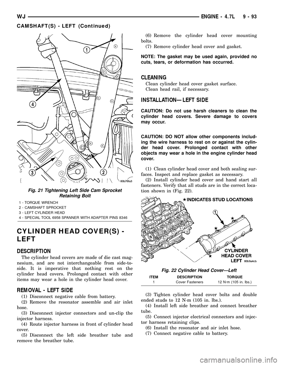
tion shown in (Fig. 22).
(3) Tighten cylinder head cover bolts and double
ended studs to 12 N´m (105 in. lbs.).
(4) Install left side breather and connect breather
tube.
(5) Connect injector electrical connectors and injec-
tor harness retaining clips.
(6) Install the resonator and air inlet hose.
(7) Connect negative cable to battery.
Fig. 21 Tightening Left Side Cam Sprocket
Retaining Bolt
1 - TORQUE WRENCH
2 - CAMSHAFT SPROCKET
3 - LEFT CYLINDER HEAD
4 - SPECIAL TOOL 6958 SPANNER WITH ADAPTER PINS 8346
Fig. 22 Cylinder Head CoverÐLeft
ITEM DESCRIPTION TORQUE
1 Cover Fasteners 12 N´m (105 in. lbs.)
WJENGINE - 4.7L 9 - 93
CAMSHAFT(S) - LEFT (Continued)
Page 1347 of 2199
CYLINDER HEAD COVER(S) -
RIGHT
DESCRIPTION
The cylinder head covers are made of die cast mag-
nesium, and are not interchangeable from side-to-
side. It is imperative that nothing rest on the
cylinder head covers. Prolonged contact with other
items may wear a hole in the cylinder head cover.
REMOVAL - RIGHT SIDE
(1) Disconnect battery negative cable.
(2) Remove air cleaner assembly, resonator assem-
bly and air inlet hose.
(3) Drain cooling system (Refer to 7 - COOLING -
STANDARD PROCEDURE).
(4) Remove accessory drive belt (Refer to 7 -
COOLING/ACCESSORY DRIVE/DRIVE BELTS -
REMOVAL).
(5) Remove air conditioning compressor retaining
bolts and move compressor to the left.
(6) Remove heater hoses.
(7) Disconnect injector and ignition coil connectors.
(8) Disconnect and remove positive crankcase ven-
tilation (PCV) hose.
(9) Remove oil fill tube.
(10) Un-clip injector and ignition coil harness and
move away from cylinder head cover.
(11) Remove right rear breather tube and filter
assembly.
(12) Remove cylinder head cover retaining bolts.
(13) Remove cylinder head cover.
NOTE: The gasket may be used again, provided no
cuts, tears, or deformation has occurred.
CLEANING
Clean cylinder head cover gasket surface.
Clean head rail, if necessary.
INSTALLATION - RIGHT SIDE
CAUTION: Do not use harsh cleaners to clean the
cylinder head covers. Severe damage to covers
may occur.
CAUTION: DO NOT allow other components includ-
ing the wire harness to rest on or against the
engine cylinder head cover. Prolonged contact with
other objects may wear a hole in the cylinder head
cover.
(1) Clean cylinder head cover and both sealing sur-
faces. Inspect and replace gasket as necessary.(2) Install cylinder head cover and hand start all
fasteners. Verify that all double ended studs are in
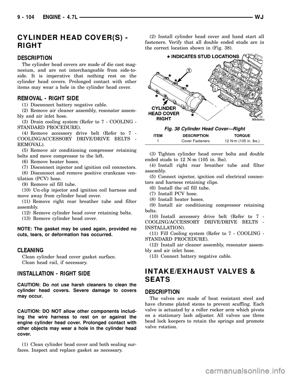
the correct location shown in (Fig. 38).
(3) Tighten cylinder head cover bolts and double
ended studs to 12 N´m (105 in. lbs).
(4) Install right rear breather tube and filter
assembly.
(5) Connect injector, ignition coil electrical connec-
tors and harness retaining clips.
(6) Install the oil fill tube.
(7) Install PCV hose.
(8) Install heater hoses.
(9) Install air conditioning compressor retaining
bolts.
(10) Install accessory drive belt (Refer to 7 -
COOLING/ACCESSORY DRIVE/DRIVE BELTS -
INSTALLATION).
(11) Fill Cooling system (Refer to 7 - COOLING -
STANDARD PROCEDURE).
(12) Install air cleaner assembly, resonator assem-
bly and air inlet hose.
(13) Connect battery negative cable.
INTAKE/EXHAUST VALVES &
SEATS
DESCRIPTION
The valves are made of heat resistant steel and
have chrome plated stems to prevent scuffing. Each
valve is actuated by a roller rocker arm which pivots
on a stationary lash adjuster. All valves use three
bead lock keepers to retain the springs and promote
valve rotation.
Fig. 38 Cylinder Head CoverÐRight
ITEM DESCRIPTION TORQUE
1 Cover Fasteners 12 N´m (105 in. lbs.)
9 - 104 ENGINE - 4.7LWJ
Page 1427 of 2199
(1) Remove fuel tank. Refer to Fuel Tank Removal/
Installation.(2) Remove fuel pump module. Refer to Fuel Pump
Module Removal/Installation.
(3) Remove electrical wire connector at sending
unit terminals.
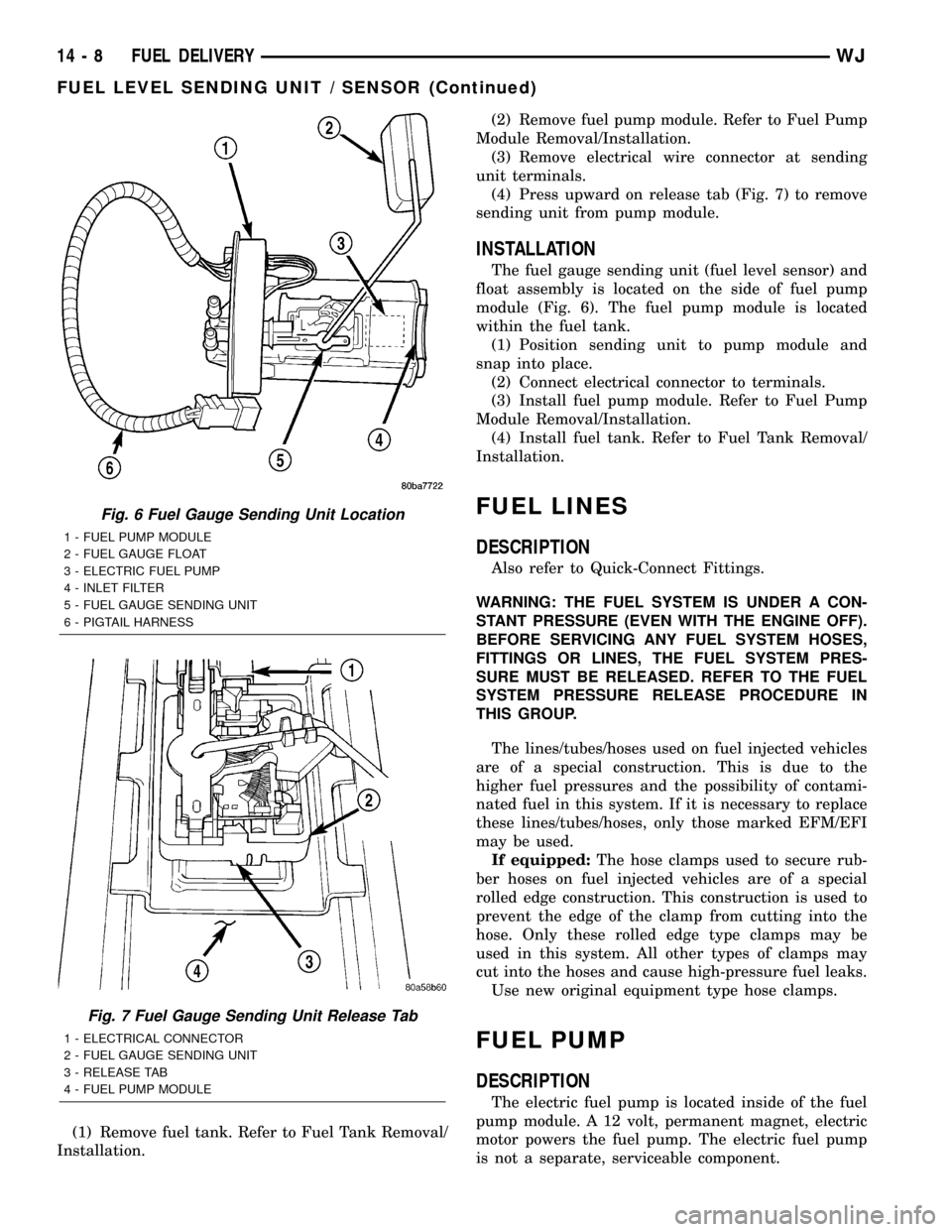
(4) Press upward on release tab (Fig. 7) to remove
sending unit from pump module.
INSTALLATION
The fuel gauge sending unit (fuel level sensor) and
float assembly is located on the side of fuel pump
module (Fig. 6). The fuel pump module is located
within the fuel tank.
(1) Position sending unit to pump module and
snap into place.
(2) Connect electrical connector to terminals.
(3) Install fuel pump module. Refer to Fuel Pump
Module Removal/Installation.
(4) Install fuel tank. Refer to Fuel Tank Removal/
Installation.
FUEL LINES
DESCRIPTION
Also refer to Quick-Connect Fittings.
WARNING: THE FUEL SYSTEM IS UNDER A CON-
STANT PRESSURE (EVEN WITH THE ENGINE OFF).
BEFORE SERVICING ANY FUEL SYSTEM HOSES,
FITTINGS OR LINES, THE FUEL SYSTEM PRES-
SURE MUST BE RELEASED. REFER TO THE FUEL
SYSTEM PRESSURE RELEASE PROCEDURE IN
THIS GROUP.
The lines/tubes/hoses used on fuel injected vehicles
are of a special construction. This is due to the
higher fuel pressures and the possibility of contami-
nated fuel in this system. If it is necessary to replace
these lines/tubes/hoses, only those marked EFM/EFI
may be used.
If equipped:The hose clamps used to secure rub-
ber hoses on fuel injected vehicles are of a special
rolled edge construction. This construction is used to
prevent the edge of the clamp from cutting into the
hose. Only these rolled edge type clamps may be
used in this system. All other types of clamps may
cut into the hoses and cause high-pressure fuel leaks.
Use new original equipment type hose clamps.
FUEL PUMP
DESCRIPTION
The electric fuel pump is located inside of the fuel
pump module. A 12 volt, permanent magnet, electric
motor powers the fuel pump. The electric fuel pump
is not a separate, serviceable component.
Fig. 6 Fuel Gauge Sending Unit Location
1 - FUEL PUMP MODULE
2 - FUEL GAUGE FLOAT
3 - ELECTRIC FUEL PUMP
4 - INLET FILTER
5 - FUEL GAUGE SENDING UNIT
6 - PIGTAIL HARNESS
Fig. 7 Fuel Gauge Sending Unit Release Tab
1 - ELECTRICAL CONNECTOR
2 - FUEL GAUGE SENDING UNIT
3 - RELEASE TAB
4 - FUEL PUMP MODULE
14 - 8 FUEL DELIVERYWJ
FUEL LEVEL SENDING UNIT / SENSOR (Continued)
Page 1432 of 2199
(e) Use DRB scan tool to power fuel pump. If
pressure is now within specifications, replace fuel
filter/fuel pressure regulator.
(f) If pressure is still low, replace fuel pump
module.
(4) If operating pressure is above 54.2 psi, electric
fuel pump is OK, but fuel pressure regulator is defec-
tive. Replace fuel filter/fuel pressure regulator.
(5) Install test port cap to fuel rail test port.
FUEL PUMP MODULE
DESCRIPTION
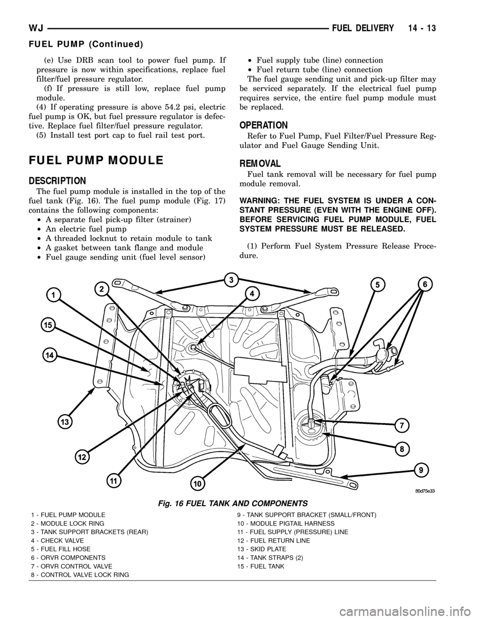
The fuel pump module is installed in the top of the
fuel tank (Fig. 16). The fuel pump module (Fig. 17)
contains the following components:
²A separate fuel pick-up filter (strainer)
²An electric fuel pump
²A threaded locknut to retain module to tank
²A gasket between tank flange and module
²Fuel gauge sending unit (fuel level sensor)²Fuel supply tube (line) connection
²Fuel return tube (line) connection
The fuel gauge sending unit and pick-up filter may
be serviced separately. If the electrical fuel pump
requires service, the entire fuel pump module must
be replaced.
OPERATION
Refer to Fuel Pump, Fuel Filter/Fuel Pressure Reg-
ulator and Fuel Gauge Sending Unit.
REMOVAL
Fuel tank removal will be necessary for fuel pump
module removal.
WARNING: THE FUEL SYSTEM IS UNDER A CON-
STANT PRESSURE (EVEN WITH THE ENGINE OFF).
BEFORE SERVICING FUEL PUMP MODULE, FUEL
SYSTEM PRESSURE MUST BE RELEASED.
(1) Perform Fuel System Pressure Release Proce-
dure.
Fig. 16 FUEL TANK AND COMPONENTS
1 - FUEL PUMP MODULE 9 - TANK SUPPORT BRACKET (SMALL/FRONT)
2 - MODULE LOCK RING 10 - MODULE PIGTAIL HARNESS
3 - TANK SUPPORT BRACKETS (REAR) 11 - FUEL SUPPLY (PRESSURE) LINE
4 - CHECK VALVE 12 - FUEL RETURN LINE
5 - FUEL FILL HOSE 13 - SKID PLATE
6 - ORVR COMPONENTS 14 - TANK STRAPS (2)
7 - ORVR CONTROL VALVE 15 - FUEL TANK
8 - CONTROL VALVE LOCK RING
WJFUEL DELIVERY 14 - 13
FUEL PUMP (Continued)
Page 1435 of 2199
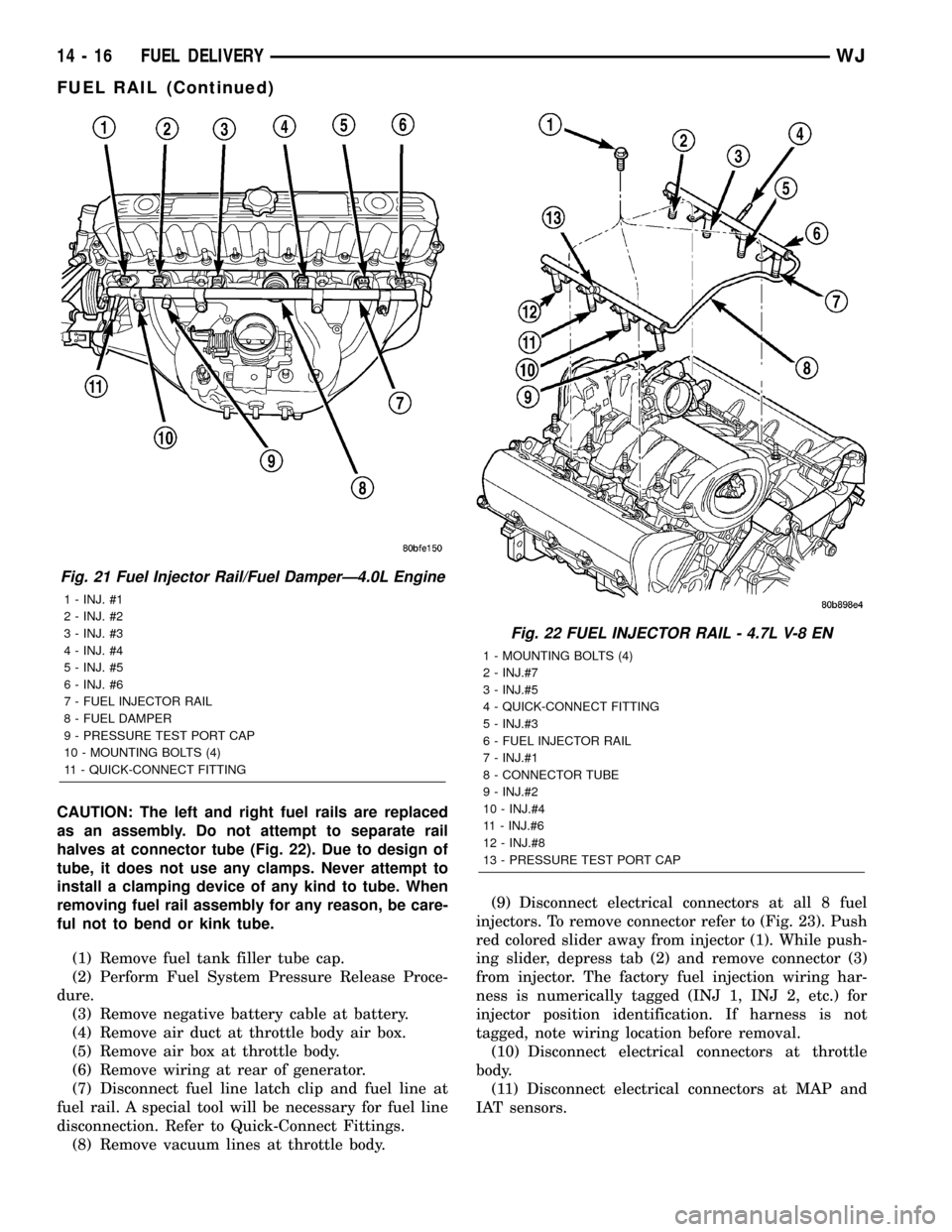
CAUTION: The left and right fuel rails are replaced
as an assembly. Do not attempt to separate rail
halves at connector tube (Fig. 22). Due to design of
tube, it does not use any clamps. Never attempt to
install a clamping device of any kind to tube. When
removing fuel rail assembly for any reason, be care-
ful not to bend or kink tube.
(1) Remove fuel tank filler tube cap.
(2) Perform Fuel System Pressure Release Proce-
dure.
(3) Remove negative battery cable at battery.
(4) Remove air duct at throttle body air box.
(5) Remove air box at throttle body.
(6) Remove wiring at rear of generator.
(7) Disconnect fuel line latch clip and fuel line at
fuel rail. A special tool will be necessary for fuel line
disconnection. Refer to Quick-Connect Fittings.
(8) Remove vacuum lines at throttle body.(9) Disconnect electrical connectors at all 8 fuel
injectors. To remove connector refer to (Fig. 23). Push
red colored slider away from injector (1). While push-
ing slider, depress tab (2) and remove connector (3)
from injector. The factory fuel injection wiring har-
ness is numerically tagged (INJ 1, INJ 2, etc.) for
injector position identification. If harness is not
tagged, note wiring location before removal.
(10) Disconnect electrical connectors at throttle
body.
(11) Disconnect electrical connectors at MAP and
IAT sensors.
Fig. 21 Fuel Injector Rail/Fuel DamperÐ4.0L Engine
1 - INJ. #1
2 - INJ. #2
3 - INJ. #3
4 - INJ. #4
5 - INJ. #5
6 - INJ. #6
7 - FUEL INJECTOR RAIL
8 - FUEL DAMPER
9 - PRESSURE TEST PORT CAP
10 - MOUNTING BOLTS (4)
11 - QUICK-CONNECT FITTING
Fig. 22 FUEL INJECTOR RAIL - 4.7L V-8 EN
1 - MOUNTING BOLTS (4)
2 - INJ.#7
3 - INJ.#5
4 - QUICK-CONNECT FITTING
5 - INJ.#3
6 - FUEL INJECTOR RAIL
7 - INJ.#1
8 - CONNECTOR TUBE
9 - INJ.#2
10 - INJ.#4
11 - INJ.#6
12 - INJ.#8
13 - PRESSURE TEST PORT CAP
14 - 16 FUEL DELIVERYWJ
FUEL RAIL (Continued)
Page 1436 of 2199
(12) Remove first three ignition coils on each bank
(cylinders #1, 3, 5, 2, 4 and 6). Refer to Ignition Coil
Removal/Installation.
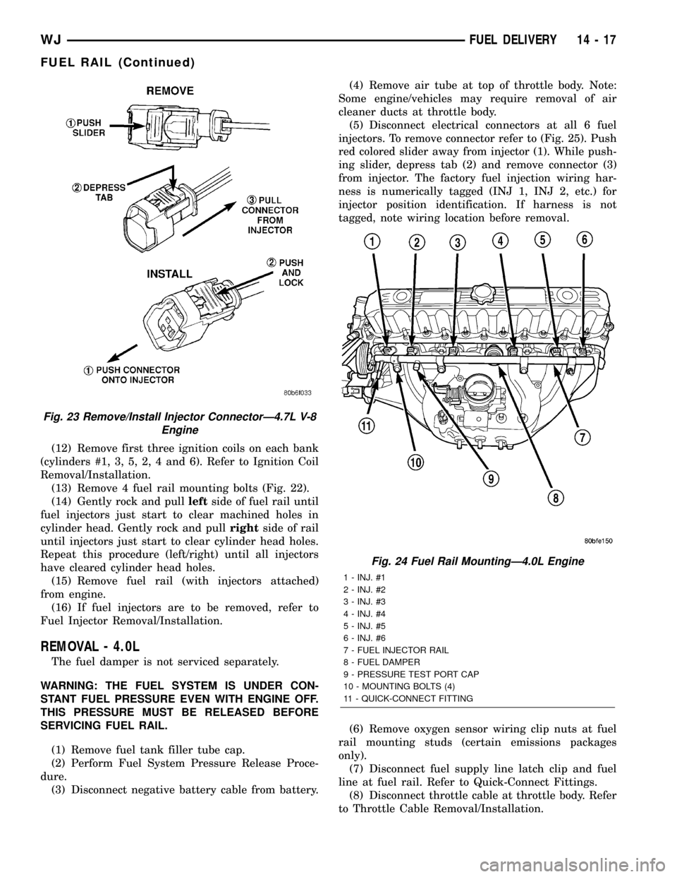
(13) Remove 4 fuel rail mounting bolts (Fig. 22).
(14) Gently rock and pullleftside of fuel rail until
fuel injectors just start to clear machined holes in
cylinder head. Gently rock and pullrightside of rail
until injectors just start to clear cylinder head holes.
Repeat this procedure (left/right) until all injectors
have cleared cylinder head holes.
(15) Remove fuel rail (with injectors attached)
from engine.
(16) If fuel injectors are to be removed, refer to
Fuel Injector Removal/Installation.
REMOVAL - 4.0L
The fuel damper is not serviced separately.
WARNING: THE FUEL SYSTEM IS UNDER CON-
STANT FUEL PRESSURE EVEN WITH ENGINE OFF.
THIS PRESSURE MUST BE RELEASED BEFORE
SERVICING FUEL RAIL.
(1) Remove fuel tank filler tube cap.
(2) Perform Fuel System Pressure Release Proce-
dure.
(3) Disconnect negative battery cable from battery.(4) Remove air tube at top of throttle body. Note:
Some engine/vehicles may require removal of air
cleaner ducts at throttle body.
(5) Disconnect electrical connectors at all 6 fuel
injectors. To remove connector refer to (Fig. 25). Push
red colored slider away from injector (1). While push-
ing slider, depress tab (2) and remove connector (3)
from injector. The factory fuel injection wiring har-
ness is numerically tagged (INJ 1, INJ 2, etc.) for
injector position identification. If harness is not
tagged, note wiring location before removal.
(6) Remove oxygen sensor wiring clip nuts at fuel
rail mounting studs (certain emissions packages
only).
(7) Disconnect fuel supply line latch clip and fuel
line at fuel rail. Refer to Quick-Connect Fittings.
(8) Disconnect throttle cable at throttle body. Refer
to Throttle Cable Removal/Installation.
Fig. 23 Remove/Install Injector ConnectorÐ4.7L V-8
Engine
Fig. 24 Fuel Rail MountingÐ4.0L Engine
1 - INJ. #1
2 - INJ. #2
3 - INJ. #3
4 - INJ. #4
5 - INJ. #5
6 - INJ. #6
7 - FUEL INJECTOR RAIL
8 - FUEL DAMPER
9 - PRESSURE TEST PORT CAP
10 - MOUNTING BOLTS (4)
11 - QUICK-CONNECT FITTING
WJFUEL DELIVERY 14 - 17
FUEL RAIL (Continued)