2003 JEEP GRAND CHEROKEE diesel engine
[x] Cancel search: diesel enginePage 1518 of 2199

INSTALLATION - 3/8(PRESSURE HOSE
NOTE: Lubrication and a new o-ring must be used
when reinstalling.
(1) Install the hoses to the vehicle.
(2) Reconnect the high pressure hose to the
hydraulic fan motor (Fig. 10) Tighten the hose to
22.5 N´m (17 ft.lbs.).
(3) Reconnect the high pressure hose to the power
steering gear (Fig. 10) Tighten the hose to 22.5 N´m
(17 ft.lbs.).
(4) Install the hose to the clipped position on the
fan shroud.
(5) Install the metal skid plate.
(6) Install the air box,(Refer to 9 - ENGINE/AIR
INTAKE SYSTEM/AIR CLEANER HOUSING -
INSTALLATION).
(7) Refill the power steering fluid and bleed the
system,(Refer to 19 - STEERING/PUMP - STAN-
DARD PROCEDURE).
INSTALLATION - 3/8(RETURN HOSE
(1) Install the hoses to the vehicle.
(2) Reconnect the rubber hose to the steering
cooler outlet tube (Fig. 12) Tighten the hose clamp.
(3) Reconnect the rubber hose to the power steer-
ing reservoir (Fig. 12) Tighten the hose clamp.
(4) Install the air box,(Refer to 9 - ENGINE/AIR
INTAKE SYSTEM/AIR CLEANER HOUSING -
INSTALLATION).
(5) Refill the power steering fluid and bleed the
system,(Refer to 19 - STEERING/PUMP - STAN-
DARD PROCEDURE).
INSTALLATION - 3/8(GEAR OUTLET HOSE
NOTE: Lubrication and a new o-ring must be used
when reinstalling.
(1) Install the hoses to the vehicle.
(2) Reconnect the rubber hose to the steering
cooler inlet tube (Fig. 11) Tighten the hose clamp.
(3)
Reconnect the metal tube to the power steering
gear (Fig. 11) Tighten the hose to 22.5 N´m (17 ft.lbs.).
(4) Install the air box,(Refer to 9 - ENGINE/AIR
INTAKE SYSTEM/AIR CLEANER HOUSING -
INSTALLATION).
(5) Refill the power steering fluid and bleed the
system,(Refer to 19 - STEERING/PUMP - STAN-
DARD PROCEDURE).
INSTALLATION - INLET COOLER HOSE
(1) Install the cooler hose to the vehicle.
(2) Reconnect the cooler hose at the gear.
(3) Reconnect the lower hose at cooler (Fig. 6).
Tighten the hose to 22.5 N´m (17 ft.lbs.)
(4) Install the bracket holding the cooler hoses
(Fig. 13).(5) Install the air box,(Refer to 9 - ENGINE/AIR
INTAKE SYSTEM/AIR CLEANER HOUSING -
INSTALLATION).
(6) Install the grille opening reinforcement panel
(7) Install the front fascia grille assembly, (Refer to
13 - FRAMES & BUMPERS/BUMPERS/FRONT
FASCIA - INSTALLATION).
(8) Reconnect negative battery cable at battery.
(9) Refill the power steering fluid and bleed the
system,(Refer to 19 - STEERING/PUMP - STAN-
DARD PROCEDURE).
INSTALLATION - OUTLET COOLER HOSE
(1) Install the cooler hose to the vehicle.
(2) Reconnect the cooler hose at the reservoir.
(3) Reconnect the upper hose at the cooler (Fig. 6).
Tighten the hose to 22.5 N´m (17 ft. lbs.)
(4) Install the bracket holding the cooler hoses
(Fig. 13). Tighten the bracket to 22.5 N´m (17 ft. lbs.)
(5) Install the air box,(Refer to 9 - ENGINE/AIR
INTAKE SYSTEM/AIR CLEANER HOUSING -
INSTALLATION).
(6) Install the grille opening reinforcement panel
(7) Install the front fascia grille assembly, (Refer to
13 - FRAMES & BUMPERS/BUMPERS/FRONT
FASCIA - INSTALLATION).
(8) Reconnect negative battery cable at battery.
(9) Refill the power steering fluid and bleed the
system,(Refer to 19 - STEERING/PUMP - STAN-
DARD PROCEDURE).
PULLEY
DESCRIPTION
POWER STEERING PUMP PULLEY - 3.1L
DIESEL
To service the power steering pump pulley on the
3.1L turbo diesel engine. Refer to the power steering
pump removal and installation procedure in this
group. The pulley must be removed to service the
pump assembly. Detailed instructions are provided in
the pump procedure.
REMOVAL
CAUTION: On vehicles equipped with the 4.0L or
4.7L, Do not reuse the old power steering pump
pulley it is not intended for reuse. A new pulley
must be installed if removed.
(1) Remove pump assembly.
(2) Remove pulley from pump with Puller C-4333
or equivalent puller (Fig. 14).
WJPUMP 19 - 41
HOSES - 4.7L (Continued)
Page 2085 of 2199

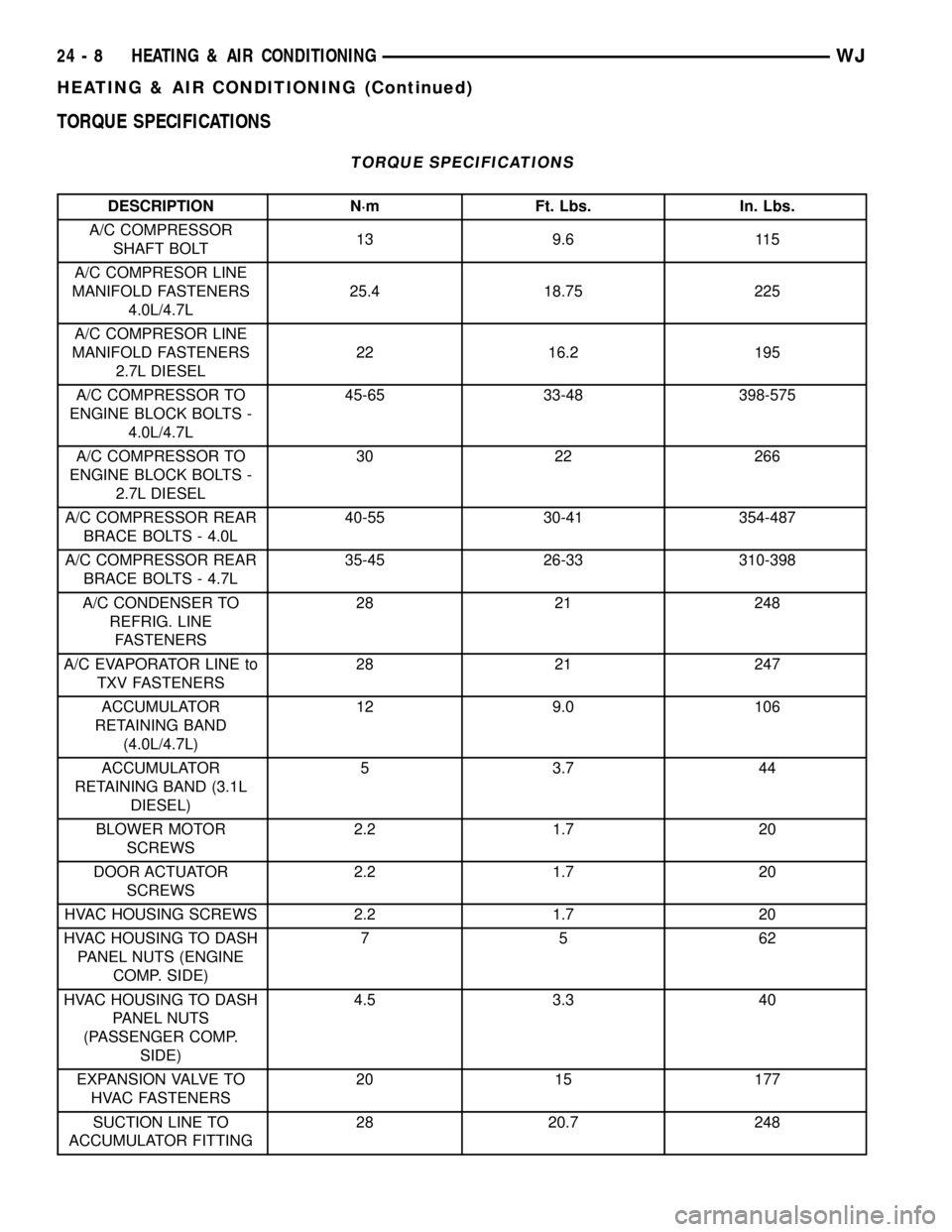
TORQUE SPECIFICATIONS
TORQUE SPECIFICATIONS
DESCRIPTION N´m Ft. Lbs. In. Lbs.
A/C COMPRESSOR
SHAFT BOLT13 9.6 115
A/C COMPRESOR LINE
MANIFOLD FASTENERS
4.0L/4.7L25.4 18.75 225
A/C COMPRESOR LINE
MANIFOLD FASTENERS
2.7L DIESEL22 16.2 195
A/C COMPRESSOR TO
ENGINE BLOCK BOLTS -
4.0L/4.7L45-65 33-48 398-575
A/C COMPRESSOR TO
ENGINE BLOCK BOLTS -
2.7L DIESEL30 22 266
A/C COMPRESSOR REAR
BRACE BOLTS - 4.0L40-55 30-41 354-487
A/C COMPRESSOR REAR
BRACE BOLTS - 4.7L35-45 26-33 310-398
A/C CONDENSER TO
REFRIG. LINE
FASTENERS28 21 248
A/C EVAPORATOR LINE to
TXV FASTENERS28 21 247
ACCUMULATOR
RETAINING BAND
(4.0L/4.7L)12 9.0 106
ACCUMULATOR
RETAINING BAND (3.1L
DIESEL)5 3.7 44
BLOWER MOTOR
SCREWS2.2 1.7 20
DOOR ACTUATOR
SCREWS2.2 1.7 20
HVAC HOUSING SCREWS 2.2 1.7 20
HVAC HOUSING TO DASH
PANEL NUTS (ENGINE
COMP. SIDE)75 62
HVAC HOUSING TO DASH
PANEL NUTS
(PASSENGER COMP.
SIDE)4.5 3.3 40
EXPANSION VALVE TO
HVAC FASTENERS20 15 177
SUCTION LINE TO
ACCUMULATOR FITTING28 20.7 248
24 - 8 HEATING & AIR CONDITIONINGWJ
HEATING & AIR CONDITIONING (Continued)
Page 2140 of 2199

(11) Remove the bolts that secure the upper con-
denser and transmission cooler.
(12) Carefully lift the condenser out of the vehicle.
INSTALLATION
WARNING: REVIEW THE WARNINGS AND CAU-
TIONS IN THE FRONT OF THIS SECTION BEFORE
PERFORMING THE FOLLOWING OPERATION.
(Refer to 24 - HEATING & AIR CONDITIONING/
PLUMBING - WARNING) (Refer to 24 - HEATING &
AIR CONDITIONING/PLUMBING - CAUTION)
Any kinks or sharp bends in the refrigerant plumb-
ing will reduce the capacity of the entire air condi-
tioning system. Kinks and sharp bends reduce the
flow of refrigerant in the system. A good rule for the
flexible hose refrigerant lines is to keep the radius of
all bends at least ten times the diameter of the hose.
In addition, the flexible hose refrigerant lines should
be routed so they are at least 80 millimeters (3
inches) from the exhaust manifold.
High pressures are produced in the refrigerant sys-
tem when the air conditioning compressor is operat-
ing. Extreme care must be exercised to make sure
that each of the refrigerant system connections is
pressure-tight and leak free. It is a good practice to
inspect all flexible hose refrigerant lines at least once
a year to make sure they are in good condition and
properly routed.
CAUTION: Before removing the condenser, note the
location of each of the radiator and condenser air
seals. These seals are used to direct air through the
condenser and radiator. The air seals must be rein-
stalled in their proper locations in order for the air
conditioning and engine cooling systems to per-
form as designed.
(1) Carefully position the condenser in the vehicle.
(2) Install the bolts that secure the upper con-
denser and transmission cooler.
(3) Remove the tape or plugs from the refrigerant
line fittings on the condenser inlet and the discharge
line. Connect the discharge line to the condenser
inlet. Tighten the retaining nut to 28 N´m (250 in.
lbs.).
(4) Remove the tape or plugs from the refrigerant
line fittings on the condenser outlet and the liquid
line. Connect the liquid line to the condenser outlet.
Tighten the retaining nut to 28 N´m (250 in. lbs.).
(5) Install the headlamp mounting module and
front fascia. Refer to Body for the procedure.
(6) Install the engine air filter inlet duct.
(7) Install the bolts that secure the radiator to the
upper crossmember.(8) Install the nuts that secure the hood latch and
brace to the upper crossmember.
(9) Install the headlamps in their mounts.
(10) Install the screws attaching the grille and
headlamp mounting module to the upper crossmem-
ber of the vehicle. Refer to Body for this and further
steps in the procedure.
(11) Evacuate and Recharge the refrigerant sys-
tem. (Refer to 24 - HEATING & AIR CONDITION-
ING/PLUMBING - STANDARD PROCEDURE -
REFRIGERANT SYSTEM EVACUATE) (Refer to 24 -
HEATING & AIR CONDITIONING/PLUMBING -
STANDARD PROCEDURE - REFRIGERANT SYS-
TEM CHARGE)
(12) Connect the battery negative cable.
NOTE: If the condenser is replaced, add 30 millili-
ters (1 fluid ounce) of refrigerant oil to the refriger-
ant system. Use only refrigerant oil of the type
recommended for the compressor in the vehicle.
(Refer to 24 - HEATING & AIR CONDITIONING/
PLUMBING/REFRIGERANT OIL - DESCRIPTION)
A/C DISCHARGE LINE
REMOVAL
REMOVAL - 2.7L TURBO DIESEL
WARNING: REVIEW THE WARNINGS AND CAU-
TIONS IN THE FRONT OF THIS SECTION BEFORE
PERFORMING THE FOLLOWING OPERATION.
(Refer to 24 - HEATING & AIR CONDITIONING/
PLUMBING - WARNING) (Refer to 24 - HEATING &
AIR CONDITIONING/PLUMBING - CAUTION)
(1) Disconnect and isolate the negative battery
cable.
(2) Recover the refrigerant system. (Refer to 24 -
HEATING & AIR CONDITIONING/PLUMBING -
STANDARD PROCEDURE - REFRIGERANT
RECOVERY)
(3) Remove both headlamps from the vehicle. Refer
to Lamps/Lighting for the procedure.
(4) Remove the a/c high pressure transducer(Refer
to 24 - HEATING & AIR CONDITIONING/CON-
TROLS/A/C PRESSURE TRANSDUCER - REMOV-
AL).
(5) Remove the front fascia from the vehicle. Refer
to Front Fascia for the procedure (Fig. 7).
(6) Remove the refrigerant line retaining fastener
from the condenser inlet fitting. Remove the line and
cap the condenser inlet tube to prevent contamina-
tion of the system.
WJPLUMBING 24 - 63
A/C CONDENSER (Continued)
Page 2153 of 2199

VISCOUS HEATER
DESCRIPTION
DESCRIPTION
The diesel engine has an engine mounted mechan-
ical device called a Viscous Heater that is used to
heat the coolant coming from the engine to the
heater core. The Viscous Heater is driven by the
engine fan belt and has a electro-mechanical clutch
which is controlled by the HVAC control unit.
DESCRIPTION - VISCOUS HEATER CLUTCH
The basic viscous heater clutch assembly consists
of a stationary electromagnetic coil, a hub bearing
and pulley assembly and a clutch plate. The electro-
magnetic coil unit and the hub bearing and pulley
assembly are each retained on the nose of the com-
pressor front housing with snap rings (Fig. 17). The
clutch plate is keyed to the viscous heater shaft and
secured with a nut. These components provide the
means to engage and disengage the viscous heater
from the engine accessory drive belt.
OPERATION
OPERATION - VISCOUS HEATER
The Viscous Heater is driven by the engine fan
belt. The Viscous Heater has an electro-mechanical
clutch that receives a signal from the HVAC control
head and the Viscous Heater controller that ener-
gizes and engages the clutch. Once engaged theclutch allows the Viscous Heater to increase the tem-
perature of the coolant flowing to the heater core,
which provides heat the passenger compartment
quicker than normal engines without the Viscous
Heater. The Viscous Heater generates heat by means
of friction which heats a special Silicon Oil within its
housing which is then transferred to the engine cool-
ant when the coolant passes over fins within the
pump. Please note that the coolant is isolated from
the silicon oil within the pump housing. When
demand for passenger compartment heat decreases
the Viscous Heater clutch will receive an input from
the Viscous heater controller to disengage.
OPERATION - VISCOUS HEATER CLUTCH
When the clutch coil is energized, it magnetically
draws the clutch into contact with the pulley and
drives the viscous heater shaft. When the coil is not
energized the pulley freewheels on the clutch hub
bearing, which is part of the pulley. The viscous
heater clutch and coil are the only serviced parts on
the viscous heater assembly. If the viscous heater is
inoperative or damaged the entire assembly must be
replaced. The viscous heater clutch engagement is
controlled by several components: the viscous heater
controller, the engine powertrain control module and
the HVAC control head.
REMOVAL
REMOVAL - VISCOUS HEATER
(1) Drain the engine coolant(Refer to 7 - COOL-
ING/ENGINE - STANDARD PROCEDURE).
(2) Remove the engine accessory drive belt(Refer to
7 - COOLING/ACCESSORY DRIVE/DRIVE BELTS -
REMOVAL).
(3) Remove the heater hose clamps at the Viscous
Heater.
(4) Remove the heater hoses from the Viscous
Heater.
(5) Unplug the Viscous Heater clutch electrical
connector.
(6) Remove the bolts holding the Viscous Heater to
the mounting bracket.
(7) Remove the Viscous Heater from the vehicle.
REMOVAL - VISCOUS HEATER CLUTCH
(1) The viscous heater clutch can be serviced in
the vehicle and the cooling system does not have to
be drained.
(2) Disconnect and isolate the battery negative
cable.
(3) Remove the serpentine drive belt(Refer to 7 -
COOLING/ACCESSORY DRIVE/DRIVE BELTS -
REMOVAL).
Fig. 17 CLUTCH ASSEMBLY- typical
1 - CLUTCH PLATE
2 - SHAFT KEY
3 - PULLEY
4 - COIL
5 - CLUTCH SHIMS
6 - SNAP RING
7 - SNAP RING
24 - 76 PLUMBINGWJ
Page 2162 of 2199

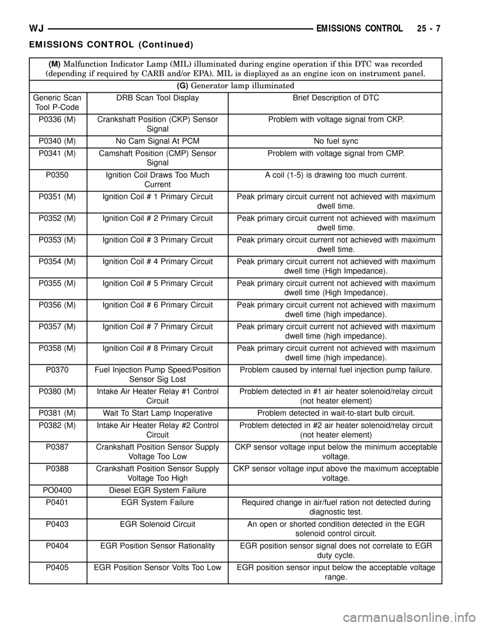
(M)Malfunction Indicator Lamp (MIL) illuminated during engine operation if this DTC was recorded
(depending if required by CARB and/or EPA). MIL is displayed as an engine icon on instrument panel.
(G)Generator lamp illuminated
Generic Scan
Tool P-CodeDRB Scan Tool Display Brief Description of DTC
P0336 (M) Crankshaft Position (CKP) Sensor
SignalProblem with voltage signal from CKP.
P0340 (M) No Cam Signal At PCM No fuel sync
P0341 (M) Camshaft Position (CMP) Sensor
SignalProblem with voltage signal from CMP.
P0350 Ignition Coil Draws Too Much
CurrentA coil (1-5) is drawing too much current.
P0351 (M) Ignition Coil # 1 Primary Circuit Peak primary circuit current not achieved with maximum
dwell time.
P0352 (M) Ignition Coil # 2 Primary Circuit Peak primary circuit current not achieved with maximum
dwell time.
P0353 (M) Ignition Coil # 3 Primary Circuit Peak primary circuit current not achieved with maximum
dwell time.
P0354 (M) Ignition Coil # 4 Primary Circuit Peak primary circuit current not achieved with maximum
dwell time (High Impedance).
P0355 (M) Ignition Coil # 5 Primary Circuit Peak primary circuit current not achieved with maximum
dwell time (High Impedance).
P0356 (M) Ignition Coil # 6 Primary Circuit Peak primary circuit current not achieved with maximum
dwell time (high impedance).
P0357 (M) Ignition Coil # 7 Primary Circuit Peak primary circuit current not achieved with maximum
dwell time (high impedance).
P0358 (M) Ignition Coil # 8 Primary Circuit Peak primary circuit current not achieved with maximum
dwell time (high impedance).
P0370 Fuel Injection Pump Speed/Position
Sensor Sig LostProblem caused by internal fuel injection pump failure.
P0380 (M) Intake Air Heater Relay #1 Control
CircuitProblem detected in #1 air heater solenoid/relay circuit
(not heater element)
P0381 (M) Wait To Start Lamp Inoperative Problem detected in wait-to-start bulb circuit.
P0382 (M) Intake Air Heater Relay #2 Control
CircuitProblem detected in #2 air heater solenoid/relay circuit
(not heater element)
P0387 Crankshaft Position Sensor Supply
Voltage Too LowCKP sensor voltage input below the minimum acceptable
voltage.
P0388 Crankshaft Position Sensor Supply
Voltage Too HighCKP sensor voltage input above the maximum acceptable
voltage.
PO0400 Diesel EGR System Failure
P0401 EGR System Failure Required change in air/fuel ration not detected during
diagnostic test.
P0403 EGR Solenoid Circuit An open or shorted condition detected in the EGR
solenoid control circuit.
P0404 EGR Position Sensor Rationality EGR position sensor signal does not correlate to EGR
duty cycle.
P0405 EGR Position Sensor Volts Too Low EGR position sensor input below the acceptable voltage
range.
WJEMISSIONS CONTROL 25 - 7
EMISSIONS CONTROL (Continued)
Page 2170 of 2199

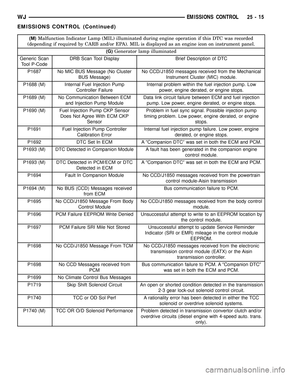
(M)Malfunction Indicator Lamp (MIL) illuminated during engine operation if this DTC was recorded
(depending if required by CARB and/or EPA). MIL is displayed as an engine icon on instrument panel.
(G)Generator lamp illuminated
Generic Scan
Tool P-CodeDRB Scan Tool Display Brief Description of DTC
P1687 No MIC BUS Message (No Cluster
BUS Message)No CCD/J1850 messages received from the Mechanical
Instrument Cluster (MIC) module.
P1688 (M) Internal Fuel Injection Pump
Controller FailureInternal problem within the fuel injection pump. Low
power, engine derated, or engine stops.
P1689 (M) No Communication Between ECM
and Injection Pump ModuleData link circuit failure between ECM and fuel injection
pump. Low power, engine derated, or engine stops.
P1690 (M) Fuel Injection Pump CKP Sensor
Does Not Agree With ECM CKP
SensorProblem in fuel sync signal. Possible injection pump
timing problem. Low power, engine derated, or engine
stops.
P1691 Fuel Injection Pump Controller
Calibration ErrorInternal fuel injection pump failure. Low power, engine
derated, or engine stops.
P1692 DTC Set In ECM A9Companion DTC9was set in both the ECM and PCM.
P1693 (M) DTC Detected in Companion Module A fault has been generated in the companion engine
control module.
P1693 (M) DTC Detected in PCM/ECM or DTC
Detected in ECMA9Companion DTC9was set in both the ECM and PCM.
P1694 Fault In Companion Module No CCD/J1850 messages received from the powertrain
control module-Aisin transmission
P1694 (M) No BUS (CCD) Messages received
from ECMBus communication failure to PCM.
P1695 No CCD/J1850 Message From Body
Control ModuleNo CCD/J1850 messages received from the body control
module.
P1696 PCM Failure EEPROM Write Denied Unsuccessful attempt to write to an EEPROM location by
the control module.
P1697 PCM Failure SRI Mile Not Stored Unsuccessful attempt to update Service Reminder
Indicator (SRI or EMR) mileage in the control module
EEPROM.
P1698 No CCD/J1850 Message From TCM No CCD/J1850 messages received from the electronic
transmission control module (EATX) or the Aisin
transmission controller.
P1698 No CCD Messages received from
PCMBus communication failure to PCM. A9Companion DTC9
was set in both the ECM and PCM.
P1699 No Climate Control Bus Messages
P1719 Skip Shift Solenoid Circuit An open or shorted condition detected in the transmission
2-3 gear lock-out solenoid control circuit.
P1740 TCC or OD Sol Perf A rationality error has been detected in either the TCC
solenoid or overdrive solenoid systems.
P1740 (M) TCC OR O/D Solenoid Performance Problem detected in transmission convertor clutch and/or
overdrive circuits (diesel engine with 4-speed auto. trans.
only).
WJEMISSIONS CONTROL 25 - 15
EMISSIONS CONTROL (Continued)