2003 JEEP GRAND CHEROKEE diesel engine
[x] Cancel search: diesel enginePage 1187 of 2199
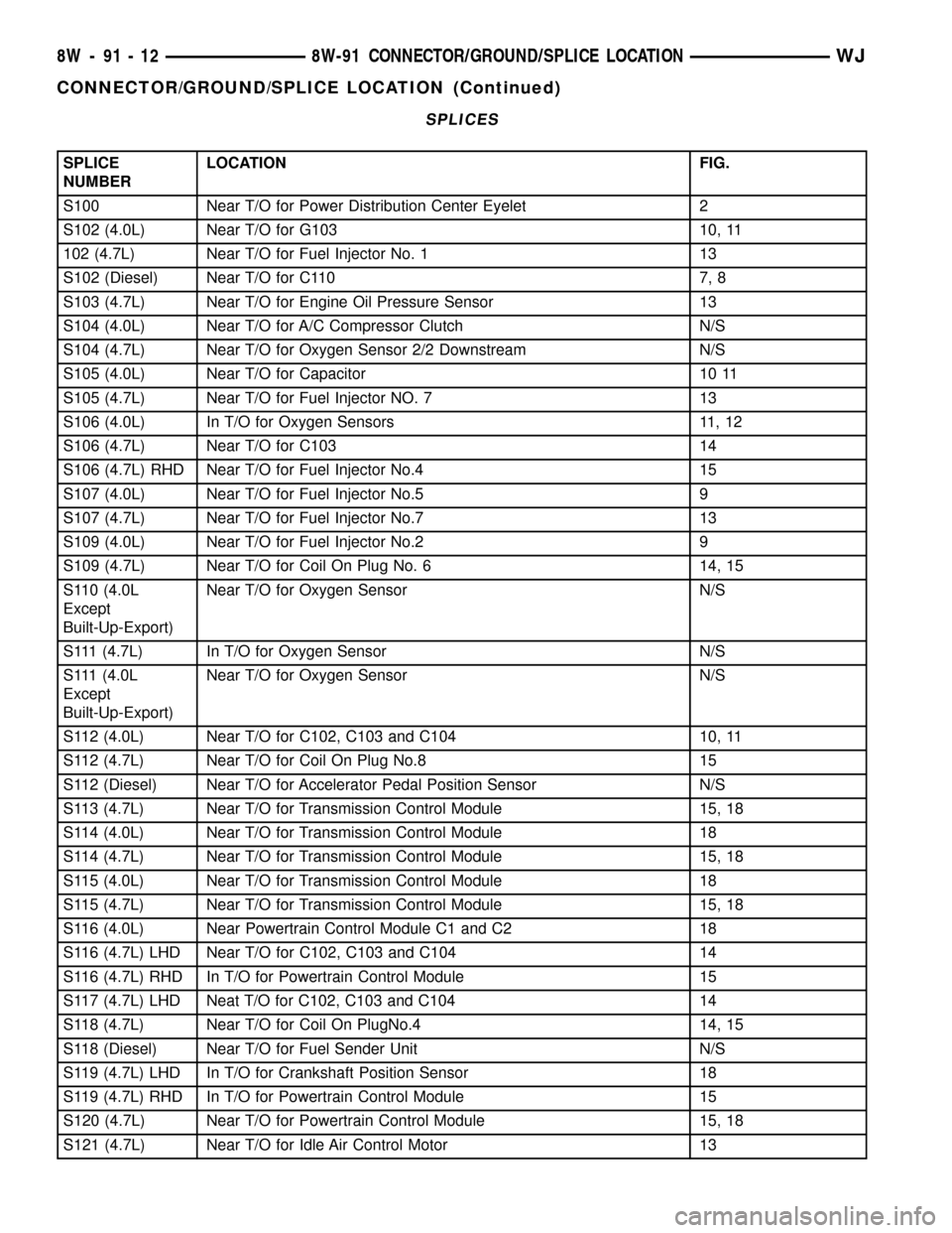
SPLICES
SPLICE
NUMBERLOCATION FIG.
S100 Near T/O for Power Distribution Center Eyelet 2
S102 (4.0L) Near T/O for G103 10, 11
102 (4.7L) Near T/O for Fuel Injector No. 1 13
S102 (Diesel) Near T/O for C110 7, 8
S103 (4.7L) Near T/O for Engine Oil Pressure Sensor 13
S104 (4.0L) Near T/O for A/C Compressor Clutch N/S
S104 (4.7L) Near T/O for Oxygen Sensor 2/2 Downstream N/S
S105 (4.0L) Near T/O for Capacitor 10 11
S105 (4.7L) Near T/O for Fuel Injector NO. 7 13
S106 (4.0L) In T/O for Oxygen Sensors 11, 12
S106 (4.7L) Near T/O for C103 14
S106 (4.7L) RHD Near T/O for Fuel Injector No.4 15
S107 (4.0L) Near T/O for Fuel Injector No.5 9
S107 (4.7L) Near T/O for Fuel Injector No.7 13
S109 (4.0L) Near T/O for Fuel Injector No.2 9
S109 (4.7L) Near T/O for Coil On Plug No. 6 14, 15
S110 (4.0L
Except
Built-Up-Export)Near T/O for Oxygen Sensor N/S
S111 (4.7L) In T/O for Oxygen Sensor N/S
S111 (4.0L
Except
Built-Up-Export)Near T/O for Oxygen Sensor N/S
S112 (4.0L) Near T/O for C102, C103 and C104 10, 11
S112 (4.7L) Near T/O for Coil On Plug No.8 15
S112 (Diesel) Near T/O for Accelerator Pedal Position Sensor N/S
S113 (4.7L) Near T/O for Transmission Control Module 15, 18
S114 (4.0L) Near T/O for Transmission Control Module 18
S114 (4.7L) Near T/O for Transmission Control Module 15, 18
S115 (4.0L) Near T/O for Transmission Control Module 18
S115 (4.7L) Near T/O for Transmission Control Module 15, 18
S116 (4.0L) Near Powertrain Control Module C1 and C2 18
S116 (4.7L) LHD Near T/O for C102, C103 and C104 14
S116 (4.7L) RHD In T/O for Powertrain Control Module 15
S117 (4.7L) LHD Neat T/O for C102, C103 and C104 14
S118 (4.7L) Near T/O for Coil On PlugNo.4 14, 15
S118 (Diesel) Near T/O for Fuel Sender Unit N/S
S119 (4.7L) LHD In T/O for Crankshaft Position Sensor 18
S119 (4.7L) RHD In T/O for Powertrain Control Module 15
S120 (4.7L) Near T/O for Powertrain Control Module 15, 18
S121 (4.7L) Near T/O for Idle Air Control Motor 13
8W - 91 - 12 8W-91 CONNECTOR/GROUND/SPLICE LOCATIONWJ
CONNECTOR/GROUND/SPLICE LOCATION (Continued)
Page 1188 of 2199
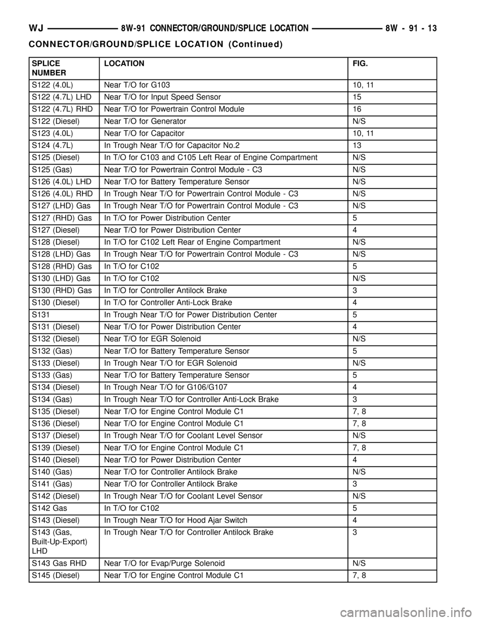
SPLICE
NUMBERLOCATION FIG.
S122 (4.0L) Near T/O for G103 10, 11
S122 (4.7L) LHD Near T/O for Input Speed Sensor 15
S122 (4.7L) RHD Near T/O for Powertrain Control Module 16
S122 (Diesel) Near T/O for Generator N/S
S123 (4.0L) Near T/O for Capacitor 10, 11
S124 (4.7L) In Trough Near T/O for Capacitor No.2 13
S125 (Diesel) In T/O for C103 and C105 Left Rear of Engine Compartment N/S
S125 (Gas) Near T/O for Powertrain Control Module - C3 N/S
S126 (4.0L) LHD Near T/O for Battery Temperature Sensor N/S
S126 (4.0L) RHD In Trough Near T/O for Powertrain Control Module - C3 N/S
S127 (LHD) Gas In Trough Near T/O for Powertrain Control Module - C3 N/S
S127 (RHD) Gas In T/O for Power Distribution Center 5
S127 (Diesel) Near T/O for Power Distribution Center 4
S128 (Diesel) In T/O for C102 Left Rear of Engine Compartment N/S
S128 (LHD) Gas In Trough Near T/O for Powertrain Control Module - C3 N/S
S128 (RHD) Gas In T/O for C102 5
S130 (LHD) Gas In T/O for C102 N/S
S130 (RHD) Gas In T/O for Controller Antilock Brake 3
S130 (Diesel) In T/O for Controller Anti-Lock Brake 4
S131 In Trough Near T/O for Power Distribution Center 5
S131 (Diesel) Near T/O for Power Distribution Center 4
S132 (Diesel) Near T/O for EGR Solenoid N/S
S132 (Gas) Near T/O for Battery Temperature Sensor 5
S133 (Diesel) In Trough Near T/O for EGR Solenoid N/S
S133 (Gas) Near T/O for Battery Temperature Sensor 5
S134 (Diesel) In Trough Near T/O for G106/G107 4
S134 (Gas) In Trough Near T/O for Controller Anti-Lock Brake 3
S135 (Diesel) Near T/O for Engine Control Module C1 7, 8
S136 (Diesel) Near T/O for Engine Control Module C1 7, 8
S137 (Diesel) In Trough Near T/O for Coolant Level Sensor N/S
S139 (Diesel) Near T/O for Engine Control Module C1 7, 8
S140 (Diesel) Near T/O for Power Distribution Center 4
S140 (Gas) Near T/O for Controller Antilock Brake N/S
S141 (Gas) Near T/O for Controller Antilock Brake 3
S142 (Diesel) In Trough Near T/O for Coolant Level Sensor N/S
S142 Gas In T/O for C102 5
S143 (Diesel) In Trough Near T/O for Hood Ajar Switch 4
S143 (Gas,
Built-Up-Export)
LHDIn Trough Near T/O for Controller Antilock Brake 3
S143 Gas RHD Near T/O for Evap/Purge Solenoid N/S
S145 (Diesel) Near T/O for Engine Control Module C1 7, 8
WJ8W-91 CONNECTOR/GROUND/SPLICE LOCATION 8W - 91 - 13
CONNECTOR/GROUND/SPLICE LOCATION (Continued)
Page 1189 of 2199
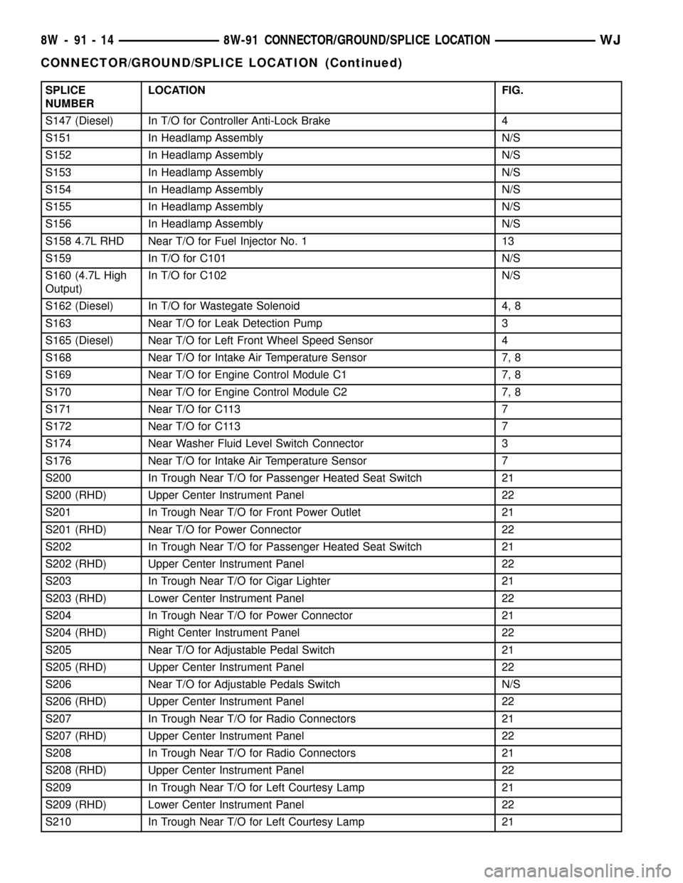
SPLICE
NUMBERLOCATION FIG.
S147 (Diesel) In T/O for Controller Anti-Lock Brake 4
S151 In Headlamp Assembly N/S
S152 In Headlamp Assembly N/S
S153 In Headlamp Assembly N/S
S154 In Headlamp Assembly N/S
S155 In Headlamp Assembly N/S
S156 In Headlamp Assembly N/S
S158 4.7L RHD Near T/O for Fuel Injector No. 1 13
S159 In T/O for C101 N/S
S160 (4.7L High
Output)In T/O for C102 N/S
S162 (Diesel) In T/O for Wastegate Solenoid 4, 8
S163 Near T/O for Leak Detection Pump 3
S165 (Diesel) Near T/O for Left Front Wheel Speed Sensor 4
S168 Near T/O for Intake Air Temperature Sensor 7, 8
S169 Near T/O for Engine Control Module C1 7, 8
S170 Near T/O for Engine Control Module C2 7, 8
S171 Near T/O for C113 7
S172 Near T/O for C113 7
S174 Near Washer Fluid Level Switch Connector 3
S176 Near T/O for Intake Air Temperature Sensor 7
S200 In Trough Near T/O for Passenger Heated Seat Switch 21
S200 (RHD) Upper Center Instrument Panel 22
S201 In Trough Near T/O for Front Power Outlet 21
S201 (RHD) Near T/O for Power Connector 22
S202 In Trough Near T/O for Passenger Heated Seat Switch 21
S202 (RHD) Upper Center Instrument Panel 22
S203 In Trough Near T/O for Cigar Lighter 21
S203 (RHD) Lower Center Instrument Panel 22
S204 In Trough Near T/O for Power Connector 21
S204 (RHD) Right Center Instrument Panel 22
S205 Near T/O for Adjustable Pedal Switch 21
S205 (RHD) Upper Center Instrument Panel 22
S206 Near T/O for Adjustable Pedals Switch N/S
S206 (RHD) Upper Center Instrument Panel 22
S207 In Trough Near T/O for Radio Connectors 21
S207 (RHD) Upper Center Instrument Panel 22
S208 In Trough Near T/O for Radio Connectors 21
S208 (RHD) Upper Center Instrument Panel 22
S209 In Trough Near T/O for Left Courtesy Lamp 21
S209 (RHD) Lower Center Instrument Panel 22
S210 In Trough Near T/O for Left Courtesy Lamp 21
8W - 91 - 14 8W-91 CONNECTOR/GROUND/SPLICE LOCATIONWJ
CONNECTOR/GROUND/SPLICE LOCATION (Continued)
Page 1196 of 2199
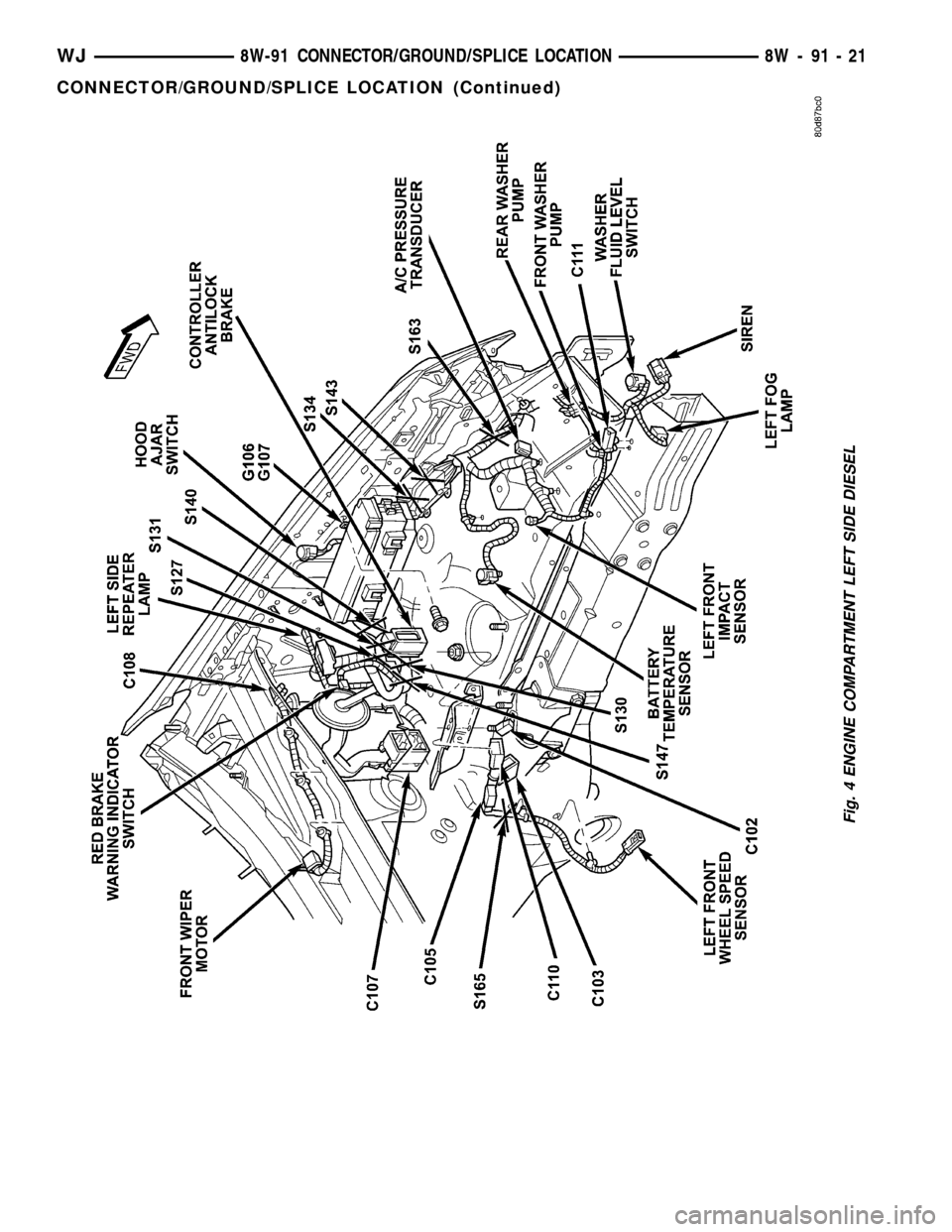
Fig. 4 ENGINE COMPARTMENT LEFT SIDE DIESEL
WJ8W-91 CONNECTOR/GROUND/SPLICE LOCATION 8W - 91 - 21
CONNECTOR/GROUND/SPLICE LOCATION (Continued)
Page 1199 of 2199
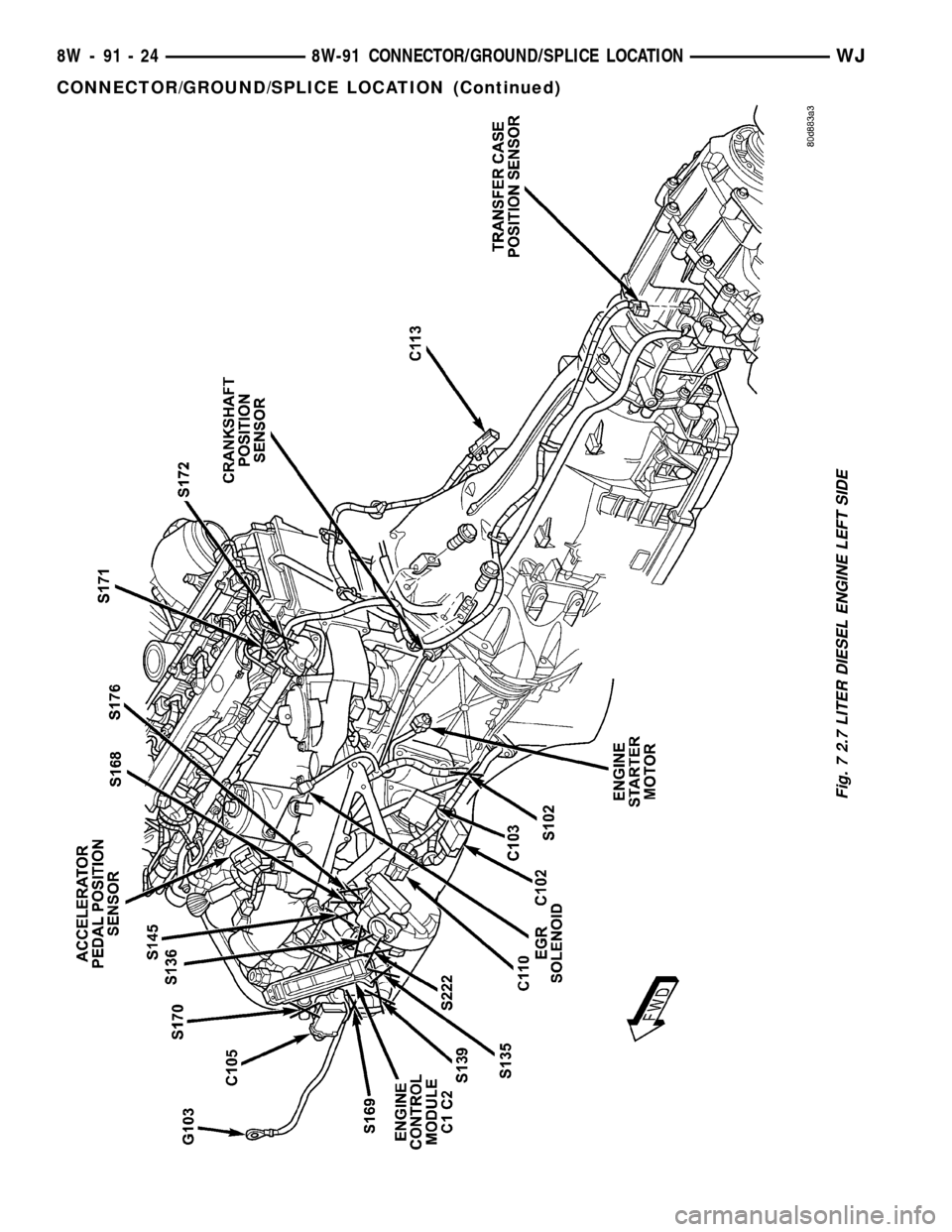
Fig. 7 2.7 LITER DIESEL ENGINE LEFT SIDE
8W - 91 - 24 8W-91 CONNECTOR/GROUND/SPLICE LOCATIONWJ
CONNECTOR/GROUND/SPLICE LOCATION (Continued)
Page 1200 of 2199
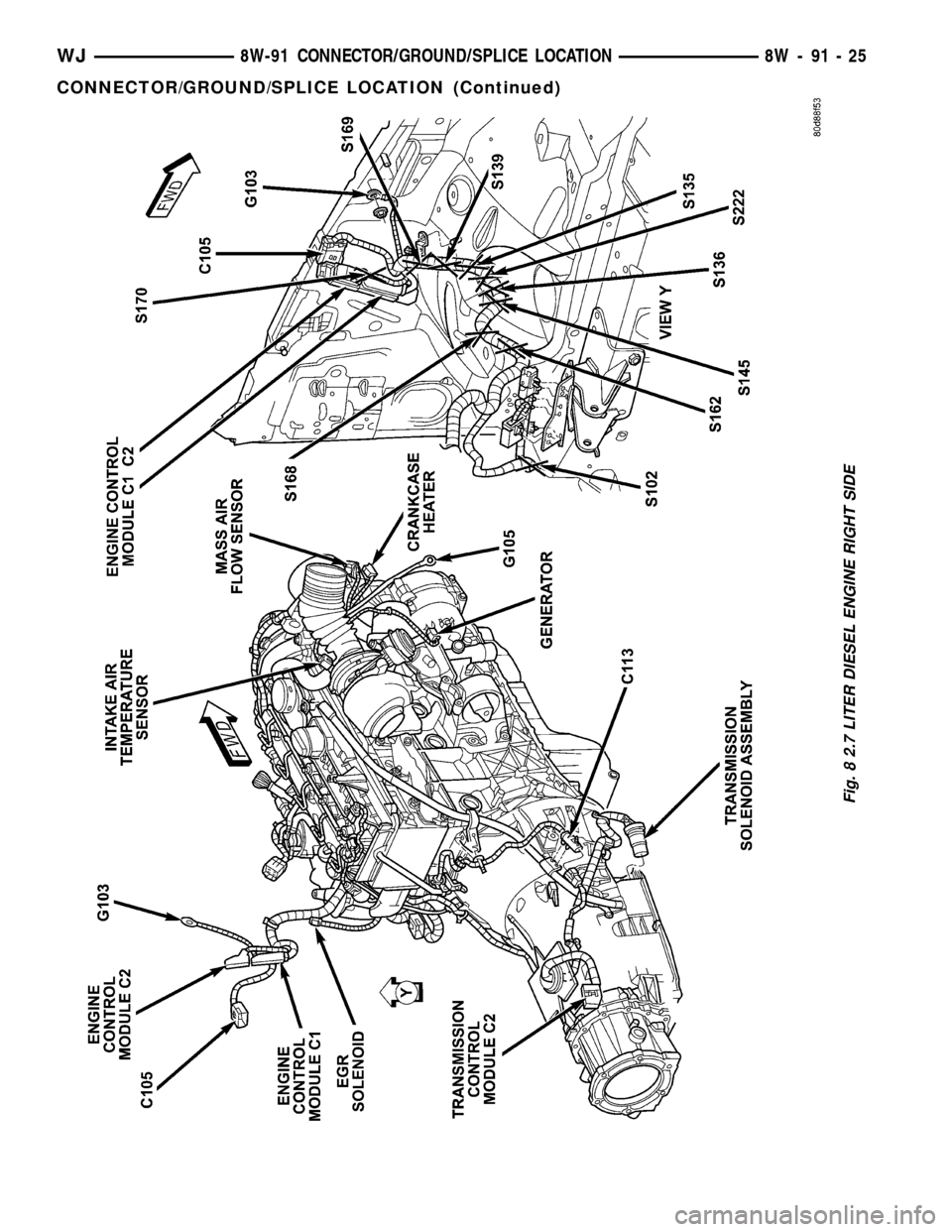
Fig. 8 2.7 LITER DIESEL ENGINE RIGHT SIDE
WJ8W-91 CONNECTOR/GROUND/SPLICE LOCATION 8W - 91 - 25
CONNECTOR/GROUND/SPLICE LOCATION (Continued)
Page 1373 of 2199
If the leakage occurs at the crankshaft rear oil seal
area:
(1) Disconnect the battery.
(2) Raise the vehicle.
(3) Remove torque converter or clutch housing
cover and inspect rear of block for evidence of oil.
Use a black light to check for the oil leak:
(a) Circular spray pattern generally indicates
seal leakage or crankshaft damage.
(b) Where leakage tends to run straight down,
possible causes are a porous block, distributor seal,
camshaft bore cup plugs oil galley pipe plugs, oil
filter runoff, and main bearing cap to cylinder
block mating surfaces.
(4) If no leaks are detected, pressurize the crank-
case as outlined in the, Inspection (Engine oil Leaks
in general)
CAUTION: Do not exceed 20.6 kPa (3 psi).
(5) If the leak is not detected, very slowly turn the
crankshaft and watch for leakage. If a leak is
detected between the crankshaft and seal while
slowly turning the crankshaft, it is possible the
crankshaft seal surface is damaged. The seal area on
the crankshaft could have minor nicks or scratches
that can be polished out with emery cloth.
CAUTION: Use extreme caution when crankshaft
polishing is necessary to remove minor nicks and
scratches. The crankshaft seal flange is especially
machined to complement the function of the rear oil
seal.
(6) For bubbles that remain steady with shaft
rotation, no further inspection can be done until dis-
assembled.
OIL
STANDARD PROCEDURE - ENGINE OIL
WARNING: NEW OR USED ENGINE OIL CAN BE
IRRITATING TO THE SKIN. AVOID PROLONGED OR
REPEATED SKIN CONTACT WITH ENGINE OIL.
CONTAMINANTS IN USED ENGINE OIL, CAUSED BY
INTERNAL COMBUSTION, CAN BE HAZARDOUS TO
YOUR HEALTH. THOROUGHLY WASH EXPOSED
SKIN WITH SOAP AND WATER. DO NOT WASH
SKIN WITH GASOLINE, DIESEL FUEL, THINNER, OR
SOLVENTS, HEALTH PROBLEMS CAN RESULT. DO
NOT POLLUTE, DISPOSE OF USED ENGINE OIL
PROPERLY.
ENGINE OIL SPECIFICATION
CAUTION: Do not use non-detergent or straight
mineral oil when adding or changing crankcase
lubricant. Engine failure can result.
API SERVICE GRADE CERTIFIED
Use an engine oil that is API Service Grade Certi-
fied. MOPARtprovides engine oils that conform to
this service grade.
SAE VISCOSITY
An SAE viscosity grade is used to specify the vis-
cosity of engine oil. Use only engine oils with multi-
ple viscosities such as 5W-30 or 10W-30 in the 4.7L
engines.The 4.7L H.O. uses 10W-30 oil only.These
are specified with a dual SAE viscosity grade which
indicates the cold-to-hot temperature viscosity range.
Select an engine oil that is best suited to your par-
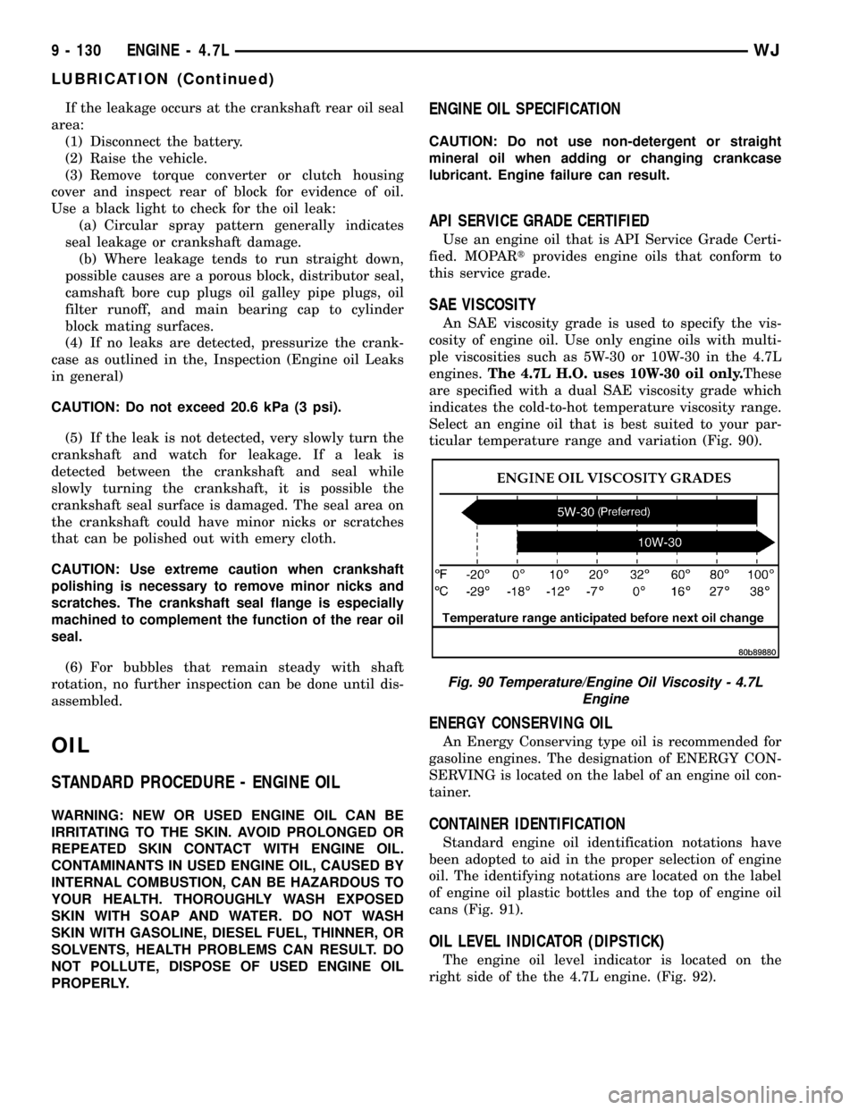
ticular temperature range and variation (Fig. 90).
ENERGY CONSERVING OIL
An Energy Conserving type oil is recommended for
gasoline engines. The designation of ENERGY CON-
SERVING is located on the label of an engine oil con-
tainer.
CONTAINER IDENTIFICATION
Standard engine oil identification notations have
been adopted to aid in the proper selection of engine
oil. The identifying notations are located on the label
of engine oil plastic bottles and the top of engine oil
cans (Fig. 91).
OIL LEVEL INDICATOR (DIPSTICK)
The engine oil level indicator is located on the
right side of the the 4.7L engine. (Fig. 92).
Fig. 90 Temperature/Engine Oil Viscosity - 4.7L
Engine
9 - 130 ENGINE - 4.7LWJ
LUBRICATION (Continued)
Page 1508 of 2199
PUMP
TABLE OF CONTENTS
page page
PUMP
DESCRIPTION - 4.0L, 4.7L................32
OPERATION
OPERATION - 4.7L....................32
OPERATION - 4.0L....................32
DIAGNOSIS AND TESTING - PUMP LEAKAGE . 33
STANDARD PROCEDURE
STANDARD PROCEDURE - INITIAL
OPERATION - 4.0L....................33
STANDARD PROCEDURE - INITIAL
OPERATION - 4.7L....................33
REMOVAL
REMOVAL - 4.0L ENGINE...............34
REMOVAL - 4.7L ENGINE...............34
INSTALLATION
INSTALLATION - 4.0L ENGINE...........34
INSTALLATION - 4.7L ENGINE...........34
SPECIFICATIONS
TORQUE CHART......................35
SPECIAL TOOLS
POWER STEERING PUMP..............36
FLUID COOLER
DESCRIPTION.........................36
REMOVAL.............................36
INSTALLATION.........................37
HOSES - 4.0L
DESCRIPTION
DESCRIPTION - PRESSURE LINE........37
DESCRIPTION - RETURN LINE...........37
OPERATION
OPERATION - PRESSURE LINE..........37
OPERATION - RETURN LINE............37
REMOVAL.............................37
INSTALLATION.........................37
HOSES - 4.7L
DESCRIPTION
DESCRIPTION - 1/2º PRESSURE HOSE....38DESCRIPTION - 1/2º RETURN HOSE......38
DESCRIPTION - 3/8º PRESSURE HOSE....38
DESCRIPTION - 3/8º GEAR OUTLET HOSE . 38
DESCRIPTION - 3/8º RETURN HOSE......38
OPERATION
OPERATION - 1/2º PRESSURE HOSE......38
OPERATION - 1/2º RETURN HOSE........38
OPERATION - 3/8º PRESSURE HOSE......39
OPERATION - 3/8º GEAR OUTLET HOSE . . . 39
OPERATION - 3/8ºRETURN HOSE........39
REMOVAL
REMOVAL - 1/29PRESSURE HOSE.......39
REMOVAL - 1/29RETURN HOSE..........39
REMOVAL - 3/89PRESSURE HOSE.......39
REMOVAL - 3/89RETURN HOSE..........39
REMOVAL - 3/89GEAR OUTLET HOSE.....40
REMOVAL - INLET COOLER HOSE........40
REMOVAL - OUTLET COOLER HOSE......40
INSTALLATION
INSTALLATION - 1/29PRESSURE HOSE....40
INSTALLATION - 1/29RETURN HOSE......40
INSTALLATION - 3/89PRESSURE HOSE....41
INSTALLATION - 3/89RETURN HOSE......41
INSTALLATION - 3/89GEAR OUTLET HOSE . 41
INSTALLATION - INLET COOLER HOSE....41
INSTALLATION - OUTLET COOLER HOSE . . 41
PULLEY
DESCRIPTION
POWER STEERING PUMP PULLEY - 3.1L
DIESEL.............................41
REMOVAL.............................41
INSTALLATION.........................42
RESERVOIR
REMOVAL.............................42
INSTALLATION.........................42
WJPUMP 19 - 31