2003 JEEP GRAND CHEROKEE Hoses
[x] Cancel search: HosesPage 644 of 2199
(2) Turn the ignition switch to the Off position.
Disconnect and isolate the battery negative cable.
Disconnect the left headlamp and dash wire harness
connector for the rear washer pump/motor unit from
the pump/motor unit connector receptacle. Check for
continuity between the ground circuit cavity of the
left headlamp and dash wire harness connector for
the rear washer pump/motor unit and a good ground.
There should be continuity. If OK, go to Step 3. If not
OK, repair the open ground circuit to ground (G106)
as required.
(3) Reconnect the battery negative cable. Turn the
ignition switch to the On position. Push the right
multi-function switch control stalk toward the instru-
ment panel to actuate the rear washer switch. With
the rear washer switch actuated, check for battery
voltage at the rear washer switch output circuit cav-
ity of the left headlamp and dash wire harness con-
nector for the rear washer pump/motor unit. If OK,
replace the faulty rear washer pump/motor unit. If
not OK, repair the open rear washer switch output
circuit between the rear washer pump/motor unit
and the right multi-function switch as required.
CLEANING - REAR WIPER & WASHER SYSTEM
WIPER SYSTEM
The squeegee of a wiper blade exposed to the ele-
ments for a long time tends to lose its wiping effec-
tiveness. Periodic cleaning of the squeegee is
suggested to remove any deposits of salt or road film.
The wiper blade, arm, and liftgate glass should only
be cleaned using a sponge or soft cloth and wind-
shield washer fluid, a mild detergent, or a non-abra-
sive cleaner. If the wiper blade continues to leave
streaks, smears, hazing, or beading on the glass after
thorough cleaning of the squeegees and the glass, the
entire wiper blade assembly must be replaced.
CAUTION: Protect the rubber squeegee of the wiper
blade from any petroleum-based cleaners, solvents,
or contaminants. These products can rapidly deteri-
orate the rubber squeegee.
WASHER SYSTEM
If the washer system is contaminated with foreign
material, drain the washer reservoir by removing the
front washer pump/motor from the reservoir. Clean
foreign material from the inside of the washer reser-
voir using clean washer fluid, a mild detergent, or a
non-abrasive cleaner. Flush foreign material from the
washer system plumbing by first disconnecting the
washer hose from the washer nozzle, then running
the washer pump/motor to run clean washer fluid or
water through the system. A plugged or restricted
washer nozzle should be carefully back-flushed usingcompressed air. If the washer nozzle obstruction can-
not be cleared, replace the washer nozzle.
CAUTION: Never introduce petroleum-based clean-
ers, solvents, or contaminants into the washer sys-
tem. These products can rapidly deteriorate the
rubber seals and hoses of the washer system, as
well as the rubber squeegee of the wiper blade.
CAUTION: Never use compressed air to flush the
washer system plumbing. Compressed air pres-
sures are too great for the washer system plumbing
components and will result in further system dam-
age. Never use sharp instruments to clear a
plugged washer nozzle or damage to the nozzle ori-
fice and improper nozzle spray patterns will result.
INSPECTION - REAR WIPER & WASHER
SYSTEM
WIPER SYSTEM
The rear wiper blade and wiper arm should be
inspected periodically, not just when wiper perfor-
mance problems are experienced. This inspection
should include the following points:
(1) Inspect the wiper arm for any indications of
damage, or contamination. If the wiper arm is con-
taminated with any foreign material, clean as
required. (Refer to 8 - ELECTRICAL/REAR WIPERS/
WASHERS - CLEANING). If a wiper arm is damaged
or corrosion is evident, replace the wiper arm with a
new unit. Do not attempt to repair a wiper arm that
is damaged or corroded.
(2) Carefully lift the wiper arm off of the ramp.
Note the action of the wiper arm hinge. The wiper
arm should pivot freely at the hinge, but with no lat-
eral looseness evident. If there is any binding evident
in the wiper arm hinge, or there is evident lateral
play in the wiper arm hinge, replace the wiper arm.
CAUTION: Do not allow the wiper arm to spring
back against the glass without the wiper blade in
place or the glass may be damaged.
(3) Once proper hinge action of the wiper arm is
confirmed, check the hinge for proper spring tension.
The spring tension of the wiper arm should be suffi-
cient to cause the rubber squeegee to conform to the
curvature of the glass. Replace a wiper arm if it has
low or no spring tension.
(4) Inspect the wiper blade and squeegee for any
indications of damage, contamination, or rubber dete-
rioration (Fig. 1). If the wiper blade or squeegee is
contaminated with any foreign material, clean them
and the glass as required. (Refer to 8 - ELECTRI-
WJREAR WIPERS/WASHERS 8R - 37
REAR WIPERS/WASHERS (Continued)
Page 645 of 2199
CAL/REAR WIPERS/WASHERS - CLEANING). If
after cleaning the wiper blade and the glass, the
wiper blade fails to clear the glass without smearing,
streaking, chattering, hazing, or beading, replace the
wiper blade. Also, if a wiper blade is damaged or if
the squeegee rubber is damaged or deteriorated,
replace the wiper blade with a new unit. Do not
attempt to repair a wiper blade that is damaged.
WASHER SYSTEM
The washer system components should be
inspected periodically, not just when washer perfor-
mance problems are experienced. This inspection
should include the following points:
(1) Check for ice or other foreign material in the
washer reservoir. If contaminated, clean and flush
the washer system. (Refer to 8 - ELECTRICAL/
REAR WIPERS/WASHERS - CLEANING).
(2) Inspect the washer plumbing for pinched, leak-
ing, deteriorated, or incorrectly routed hoses and
damaged or disconnected hose fittings. Replace dam-
aged or deteriorated hoses and hose fittings. Leaking
washer hoses can sometimes be repaired by cutting
the hose at the leak and splicing it back togetherusing an in-line connector fitting. Similarly, sections
of deteriorated hose can be cut out and replaced by
splicing in new sections of hose using in-line connec-
tor fittings. Whenever routing a washer hose or a
wire harness containing a washer hose, it must be
routed away from hot, sharp, or moving parts. Also,
sharp bends that might pinch the washer hose must
be avoided.
REAR WASHER HOSES/TUBES
DESCRIPTION
The rear washer plumbing consists of small diam-
eter rubber hoses and molded plastic inline connector
fittings (Fig. 2). The washer reservoir hose is con-
nected to the barbed outlet nipple of the rear washer
pump/motor unit below the left front wheel house
extension and routed up the washer reservoir filler
neck to the engine compartment. Just rearward of
the washer reservoir filler neck in the engine com-
partment, an inline connector with barbed nipples
joins the reservoir hose to the engine compartment
hose. The engine compartment hose is routed along
the top of the left front fender wheel house to the
dash panel. The engine compartment hose passes
through a hole with a rubber grommet in the dash
panel into the passenger compartment. Below the
instrument panel in the passenger compartment near
the left cowl side inner panel, another inline connec-
tor joins the engine compartment hose to the A-pillar
hose. The A-pillar hose is routed up the left A-pillar
to the headliner. At the headliner, an inline connector
joins the A-pillar hose to the headliner hose. The
headliner hose is routed above the headliner and
Fig. 1 Wiper Blade Inspection
1 - WORN OR UNEVEN EDGES
2 - ROAD FILM OR FOREIGN MATERIAL DEPOSITS
3 - HARD, BRITTLE, OR CRACKED
4 - DEFORMED OR FATIGUED
5 - SPLIT
6 - DAMAGED SUPPORT COMPONENTS
Fig. 2 Rear Washer Plumbing
1 - UPPER COWL PLENUM PANEL
2 - WASHER HOSE FROM ENGINE COMPARTMENT
3 - A-PILLAR WASHER HOSE
4 - HEADLINER WASHER HOSE
8R - 38 REAR WIPERS/WASHERSWJ
REAR WIPERS/WASHERS (Continued)
Page 646 of 2199

along the left roof side rail to the rear of the vehicle.
At the rear of the vehicle, the headliner hose is
routed above the headliner and along the upper lift-
gate opening panel toward the right side of the vehi-
cle. The headliner hose then passes through a hole
with a rubber grommet in the upper liftgate opening
panel and through another hole with a rubber grom-
met into the upper inner liftgate panel to the rear
washer nozzle.
Washer hose is available for service only as roll
stock, which must then be cut to length. The head-
liner washer hose is integral to the headliner unit
and, if faulty or damaged, the headliner unit must be
replaced. The molded plastic washer hose fittings
cannot be repaired. If these fittings are faulty or
damaged, they must be replaced.
OPERATION
Washer fluid in the washer reservoir is pressurized
and fed by the rear washer pump/motor through the
rear washer system plumbing and fittings to the rear
washer nozzle on the liftgate outer panel above the
liftgate glass. Whenever routing the washer hose or a
wire harness containing a washer hose, it must be
routed away from hot, sharp, or moving parts; and,
sharp bends that might pinch the hose must be
avoided.
REAR WASHER NOZZLE
DESCRIPTION
The rear washer nozzle is a fluidic type unit that
includes an integral check valve (Fig. 3). The nozzle
is constructed of molded plastic and has a rubber
seal and integral snap features on the back of it. The
nozzle is secured by a snap fit in a dedicated mount-
ing hole in the liftgate outer panel above the liftgate
flip-up glass. Within the rear nozzle body, a small
check ball is held against an integral valve seat at
the inlet end of the nozzle by a small coiled spring.
The rear washer nozzle and check valve unit cannot
be adjusted or repaired. If faulty or damaged, the
entire nozzle and check valve unit must be replaced.
OPERATION
The rear washer nozzle is designed to dispense
washer fluid into the wiper pattern area on the out-
side of the liftgate glass. Pressurized washer fluid is
fed to the nozzle from the washer reservoir by the
rear washer pump/motor through a single hose,
which is attached to a barbed nipple on the back of
the rear washer nozzle. The rear washer nozzle
incorporates a fluidic design, which causes the nozzle
to emit the pressurized washer fluid as an oscillating
stream to more effectively cover a larger area of the
glass area to be cleaned. The integral rear nozzle
check valve prevents washer fluid from draining out
of the rear washer supply hoses back to the washer
reservoir. This drain-back would result in a lengthy
delay from when the rear washer switch is actuated
until washer fluid was dispensed through the rear
washer nozzle, because the rear washer pump would
have to refill the rear washer plumbing from the res-
ervoir to the nozzle. The check valve also prevents
washer fluid from siphoning through the rear washer
nozzle after the rear washer system is turned Off.
When the rear washer pump pressurizes and pumps
washer fluid from the reservoir through the rear
washer plumbing, the fluid pressure overrides the
spring pressure applied to the check ball within the
valve and unseats the check ball, allowing washer
fluid to flow to the rear washer nozzle. When the
rear washer pump stops operating, spring pressure
seats the check ball in the valve and fluid flow in
either direction within the rear washer plumbing is
prevented.
REMOVAL
The check valve for the rear washer nozzle is inte-
gral to the nozzle.
(1) Using a trim stick or another suitable wide
flat-bladed tool, gently pry at the sides of the rear
washer nozzle to release the snap features that
secure it in the mounting hole of the liftgate outer
panel.
Fig. 3 Rear Washer Nozzle
1 - HEADLINER WASHER HOSE
2 - ROOF PANEL
3 - REAR WASHER NOZZLE
4 - LIFTGATE
WJREAR WIPERS/WASHERS 8R - 39
REAR WASHER HOSES/TUBES (Continued)
Page 1248 of 2199
CONDITION POSSIBLE CAUSES CORRECTION
3. Worn or incorrect gapped spark
plugs3. Clean plugs and set gap. (Refer to
8 - ELECTRICAL/IGNITION
CONTROL/SPARK PLUG -
CLEANING).
4. Dirt or water in fuel system 4. Clean system and replace fuel
filter
5. Faulty fuel pump 5. Install new fuel pump
6. Incorrect valve timing 6. Correct valve timing
7. Blown cylinder head gasket 7. Install new cylinder head gasket
8. Low compression 8. Test cylinder compression. (Refer
to 9 - ENGINE - DIAGNOSIS AND
TESTING).
9. Burned, warped, or pitted valves 9. Install/Reface valves as necessary
10. Plugged or restricted exhaust
system10. Install new parts as necessary
11. Faulty ignition coil rail 11. Test and replace, as necessary.
(Refer to 8 - ELECTRICAL/IGNITION
CONTROL/COIL RAIL - REMOVAL).
ENGINE STALLS OR ROUGH
IDLE1. Carbon build-up on throttle plate 1. Remove throttle body and
de-carbon. (Refer to 14 - FUEL
SYSTEM/FUEL INJECTION/
THROTTLE BODY - REMOVAL) for
correct procedure.
2. Engine idle speed too low 2. Check Idle Air Control circuit.
3. Worn or incorrectly gapped spark
plugs3. Replace or clean and re-gap spark
plugs. (Refer to 8 - ELECTRICAL/
IGNITION CONTROL/SPARK PLUG
- CLEANING)
4. Faulty coil rail 4. Test and replace, if necessary.
(Refer to 8 - ELECTRICAL/IGNITION
CONTROL/COIL RAIL - REMOVAL)
5. Intake manifold vacuum leak 5. Inspect intake manifold gasket and
vacuum hoses. Replace if necessary.
(Refer to 9 - ENGINE/MANIFOLDS/
INTAKE MANIFOLD - DIAGNOSIS
AND TESTING).
ENGINE MISSES ON
ACCELERATION1. Worn or incorrectly gapped spark
plugs1. Replace spark plugs or clean and
set gap.
2. Spark plug cables defective or
crossed2. Replace spark plug cables.
3. Dirt in fuel system 3. Clean fuel system
4. Burned, warped or pitted valves 4. Install new valves
5. Faulty coil rail 5. Test and replace as necessary.
(Refer to 8 - ELECTRICAL/IGNITION
CONTROL/COIL RAIL - REMOVAL)
WJENGINE - 4.0L 9 - 5
ENGINE - 4.0L (Continued)
Page 1255 of 2199

(7) Remove the fan assembly from the water pump
(Refer to 7 - COOLING/ENGINE/RADIATOR FAN -
REMOVAL).
(8) Remove the fan shroud.
(9) Disconnect the transmission fluid cooler lines
(automatic transmission).
(10) Discharge the A/C system (Refer to 24 -
HEATING & AIR CONDITIONING/PLUMBING -
STANDARD PROCEDURE).
(11) Remove the service valves and cap the com-
pressor ports.
(12) Remove the radiator or radiator/condenser (if
equipped with A/C).
(13) Disconnect the heater hoses at the engine
thermostat housing and water pump.
(14) Disconnect the accelerator cable, transmission
line pressure cable and speed control cable (if
equipped) from the throttle body.
(15) Remove cables from the bracket and secure
out of the way.
(16) Disconnect the body ground at the engine.
(17) Disconnect the following connectors and
secure their harness out of the way.
²Power steering pressure switch
²Coolant temperature sensor
²Six (6) fuel injector connectors
²Intake air temperature sensor
²Throttle position sensor
²Map sensor
²Crankshaft position sensor
²Oxygen sensor
²Camshaft position sensor
²Generator connector and B+ terminal wire
(18) Disconnect the coil rail electrical connections
and the oil pressure switch connector.
(19) Perform the fuel pressure release procedure
(Refer to 14 - FUEL SYSTEM/FUEL DELIVERY -
STANDARD PROCEDURE).
(20) Disconnect the fuel supply line at the injector
rail (Refer to 14 - FUEL SYSTEM/FUEL DELIVERY/
QUICK CONNECT FITTING - STANDARD PROCE-
DURE).
(21) Remove the fuel line bracket from the intake
manifold.
(22) Remove the air cleaner assembly (Fig. 5).
(23) Disconnect the hoses from the fittings at the
steering gear.
(24) Drain the pump reservoir.
(25) Cap the fittings on the hoses and steering
gear to prevent foreign objects from entering the sys-
tem.
(26) Raise and support the vehicle.
(27) Disconnect the wires from the engine starter
motor solenoid.(28) Remove the engine starter motor (Refer to 8 -
ELECTRICAL/STARTING/STARTER MOTOR -
REMOVAL).
(29) Disconnect the oxygen sensor from the
exhaust pipe.
(30) Disconnect the exhaust pipe from the mani-
fold.
(31) Remove the exhaust pipe support.
(32) Remove the bending brace (Refer to 9 -
ENGINE/ENGINE BLOCK/STRUCT SUPPORT -
REMOVAL).
(33) Remove the engine flywheel/converter housing
access cover.
(34) Mark the converter and drive plate location.
(35) Remove the converter-to-drive plate bolts.
(36) Remove the upper engine flywheel/converter
housing bolts and loosen the bottom bolts.
(37) Remove the engine mount cushion-to-engine
compartment bracket bolts.
(38) Lower the vehicle.
(39) Attach a lifting device to the engine.
(40) Raise the engine off the front supports.
(41) Place a support or floor jack under the con-
verter (or engine flywheel) housing.
(42) Remove the remaining converter (or engine
flywheel) housing bolts.
(43) Lift the engine out of the engine compart-
ment.
Fig. 5 Air Cleaner Assembly
1 - POWER STEERING PUMP
2 - AIR CLEANER ASSEMBLY
9 - 12 ENGINE - 4.0LWJ
ENGINE - 4.0L (Continued)
Page 1256 of 2199

INSTALLATION
CAUTION: When installing the engine into a vehicle
equipped with an automatic transmission, be care-
ful not to damage the trigger wheel on the engine
flywheel.
(1) Attach a lifting device to the engine and lower
the engine into the engine compartment. For easier
installation, it may be necessary to remove the
engine mount bracket as an aid in alignment of the
engine to the transmission.
(2) Align the transmission torque converter hous-
ing with the engine.
(3) Loosely install the converter housing lower
bolts and install the next higher bolt and nut on each
side.
(4) Tighten all 4 bolts finger tight.
(5) Install the engine mount brackets (if removed).
(6) Lower the engine and engine mount brackets
onto the engine compartment cushions. Install the
bolts and finger tighten the nuts.
(7) Remove the engine lifting device.
(8) Raise and support the vehicle.
(9) Install the remaining engine flywheel/converter
housing bolts. Tighten all bolts to 38 N´m (28 ft. lbs.)
torque.
(10) Install the converter-to-drive plate bolts.
(11) Ensure the installation reference marks are
aligned.
(12) Install the engine flywheel/converter housing
access cover.
(13) Install the exhaust pipe support and tighten
the screw.
(14) Install the engine bending brace (Refer to 9 -
ENGINE/ENGINE BLOCK/STRUCT SUPPORT -
INSTALLATION).
(15) Tighten the engine mount-to-bracket bolts.
(16) Connect the vehicle speed sensor wire connec-
tions and tighten the screws.
(17) Connect the exhaust pipe to the manifold.
(18) Install the engine starter motor (Refer to 8 -
ELECTRICAL/STARTING/STARTER MOTOR -
INSTALLATION).
(19) Connect the wires to the engine starter motor
solenoid.
(20) Lower the vehicle.
(21) Connect all the vacuum hoses and wire con-
nectors identified during engine removal.
(22) Remove protective caps from the power steer-
ing hoses.
(23) Connect the hoses to the fittings at the steer-
ing gear. Tighten the nut to 52 N´m (38 ft. lbs.)
torque.
(24) Fill the pump reservoir with fluid.(25) Inspect the fuel supply line o-ring(s) and
replace if necessary. Connect fuel supply line to injec-
tior rail and verify connection by pulling outward on
the line.
(26) Install the fuel line bracket to the intake
manifold.
(27) Connect the coil rail electrical connectors and
oil pressure switch connector.
(28) Connect the following electrical connectors:
²Power steering pressure switch
²Coolant temperature sensor
²Six (6) fuel injector connectors
²Intake air temperature sensor
²Throttle position sensor
²Map sensor
²Crankshaft position sensor
²Oxygen sensor
²Camshaft position sensor
²Generator connector and B+ terminal wire
(29) Connect all previously removed vacuum hoses.
(30) Connect the body ground strap.
(31) Install the throttle, transmission line pres-
sure, and speed control cables to their mounting
bracket and connect them to the throttle body.
(32) Connect the heater hoses at the engine ther-
mostat housing and water pump.
(33) Install the fan assembly (Refer to 7 - COOL-
ING/ENGINE/RADIATOR FAN - INSTALLATION).
(34) Place the fan shroud in position over the fan.
(35) Install the radiator (Refer to 7 - COOLING/
ENGINE/RADIATOR - INSTALLATION).
(36) Connect the service valves to the A/C com-
pressor ports, if equipped with A/C.
(37) Charge the air conditioner system (Refer to 24
- HEATING & AIR CONDITIONING/PLUMBING -
STANDARD PROCEDURE).
(38) Connect the radiator hoses and automatic
transmission fluid cooler pipes, if equipped.
(39) Install the fan shroud to the radiator or radi-
ator/condenser (if equipped with A/C).
(40) Install upper radiator support.
(41) Connect the upper radiator hose and tighten
the clamp.
(42) Connect the lower radiator hose and tighten
the clamp.
(43) Fill crankcase with engine oil. (Refer to
LUBRICATION & MAINTENANCE/FLUID CAPACI-
TIES - SPECIFICATIONS) for correct capacities.
(44) Fill the cooling system with reusable coolant
or new coolant (Refer to 7 - COOLING - STANDARD
PROCEDURE).
(45) Align the hood to the scribe marks. Install the
hood.
(46) Install the air cleaner assembly.
(47) Install the battery and connect the battery
cable.
WJENGINE - 4.0L 9 - 13
ENGINE - 4.0L (Continued)
Page 1263 of 2199
(2) Drain the coolant (Refer to 7 - COOLING -
STANDARD PROCEDURE) and disconnect the hoses
at the engine thermostat housing and the water
pump inlet. DO NOT waste reusable coolant. If the
solution is clean and is being drained only to service
the engine or cooling system, drain the coolant into a
clean container for reuse.
(3) Remove the air cleaner assembly (Refer to 9 -
ENGINE/AIR INTAKE SYSTEM/AIR CLEANER
HOUSING - REMOVAL).
(4) Remove the cylinder head cover (Refer to 9 -
ENGINE/CYLINDER HEAD/CYLINDER HEAD
COVER(S) - REMOVAL).
(5) Remove the capscrews, bridge and pivot assem-
blies and rocker arms (Refer to 9 - ENGINE/CYLIN-
DER HEAD/ROCKER ARM / ADJUSTER ASSY -
REMOVAL).
(6) Remove the push rods.Retain the push rods,
bridges, pivots and rocker arms in the same
order as removed.
(7) Remove the accessory drive belt (Refer to 7 -
COOLING/ACCESSORY DRIVE/DRIVE BELTS -
REMOVAL).
(8) Remove the A/C compressor mounting bolts
and secure the compressor to the side.
(9) Remove the power steering pump and bracket
from the intake manifold and water pump. Set the
pump and bracket aside. DO NOT disconnect the
hoses.
(10) Perform the Fuel System Pressure Release
procedure. (Refer to 14 - FUEL SYSTEM/FUEL
DELIVERY - STANDARD PROCEDURE).
(11) Disconnect the fuel supply line at the fuel rail.(12) Remove the intake and exhaust manifolds
from the engine cylinder head (Refer to 9 - ENGINE/
MANIFOLDS/INTAKE MANIFOLD - REMOVAL).
(13) Remove the coil rail (Refer to 8 - ELECTRI-
CAL/IGNITION CONTROL/COIL RAIL - REMOV-
AL).
(14) Remove spark plugs (Refer to 8 - ELECTRI-
CAL/IGNITION CONTROL/SPARK PLUG - REMOV-
AL).
(15) Disconnect the temperature sending unit wire
connector.
(16) Remove the engine cylinder head bolts. Bolt
No.14 cannot be removed until the head is moved for-
ward (Fig. 9). Pull bolt No.14 out as far as it will go
and then suspend the bolt in this position (tape
around the bolt).
(17) Remove the engine cylinder head and gasket
(Fig. 9).
(18) If this was the first time the bolts were
removed, put a paint dab on the top of the bolt. If the
bolts have a paint dab on the top of the bolt or it
isn't known if they were used before, discard the
bolts.
(19) Stuff clean lint free shop towels into the cyl-
inder bores.
NOTE: If the valves, springs, or seals are to be
inspected/replaced at this time, (Refer to 9 -
ENGINE/CYLINDER HEAD/INTAKE/EXHAUST
VALVES & SEATS - STANDARD PROCEDURE) for
proper inspection procedures.
Fig. 8 Cylinder Head 4.0L Engine
1 - CYLINDER HEAD BOLTS
2 - CYLINDER HEAD GASKET
3 - CYLINDER HEAD
Fig. 9 Engine Cylinder
1 - CYLINDER HEAD BOLTS
2 - CYLINDER HEAD GASKET
3 - CYLINDER HEAD
9 - 20 ENGINE - 4.0LWJ
CYLINDER HEAD (Continued)
Page 1265 of 2199
(12) Install the push rods, rocker arms, pivots and
bridges in the order they were removed (Refer to 9 -
ENGINE/CYLINDER HEAD/ROCKER ARM /
ADJUSTER ASSY - INSTALLATION).
(13) Install the engine cylinder head cover (Refer
to 9 - ENGINE/CYLINDER HEAD/CYLINDER
HEAD COVER(S) - INSTALLATION).
(14) Attach the air conditioner compressor mount-
ing bracket to the engine cylinder head and block.
Tighten the bolts to 40 N´m (30 ft. lbs.) torque.
(15) Attach the air conditioning compressor to the
bracket. Tighten the bolts to 27 N´m (20 ft. lbs.)
torque.
CAUTION: The serpentine drive belt must be routed
correctly. Incorrect routing can cause the water
pump to turn in the opposite direction causing the
engine to overheat.
(16) Install the serpentine drive belt. (Refer to 7 -
COOLING/ACCESSORY DRIVE/DRIVE BELTS -
INSTALLATION).
(17) Install the air cleaner and ducting.
(18) Connect the hoses to the engine thermostat
housing and fill the cooling system to the specified
level (Refer to 7 - COOLING - STANDARD PROCE-
DURE).
(19) The automatic transmission throttle linkage
and cable must be adjusted after completing the
engine cylinder head installation (Refer to 21 -
TRANSMISSION/TRANSAXLE/AUTOMATIC - AW4/
THROTTLE VALVE CABLE - ADJUSTMENTS).
(20) Install the temperature sending unit and con-
nect the wire connector.
(21) If equipped with air conditioning, install A/C
compressor (Refer to 24 - HEATING & AIR CONDI-
TIONING/PLUMBING/A/C COMPRESSOR -
INSTALLATION) and charge A/C system (Refer to 24
- HEATING & AIR CONDITIONING/PLUMBING -
STANDARD PROCEDURE).
(22) Connect negative cable to battery.
WARNING: USE EXTREME CAUTION WHEN THE
ENGINE IS OPERATING. DO NOT STAND IN DIRECT
LINE WITH THE FAN. DO NOT PUT HANDS NEAR
THE PULLEYS, BELTS OR FAN. DO NOT WEAR
LOOSE CLOTHING.
(23) Operate the engine with the radiator cap off.
Inspect for leaks and continue operating the engine
until the engine thermostat opens. Add coolant, if
required.CYLINDER HEAD COVER(S)
DESCRIPTION
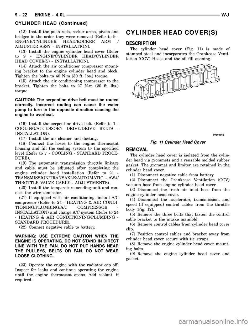
The cylinder head cover (Fig. 11) is made of
stamped steel and incorporates the Crankcase Venti-
lation (CCV) Hoses and the oil fill opening.
REMOVAL
The cylinder head cover is isolated from the cylin-
der head via grommets and a reusable molded rubber
gasket. The grommet and limiter are retained in the
cylinder head cover.
(1) Disconnect negative cable from battery.
(2) Disconnect the Crankcase Ventilation (CCV)
vacuum hose from engine cylinder head cover.
(3) Disconnect the fresh air inlet hose from the
engine cylinder head cover.
(4) Disconnect the accelerator, transmission, and
speed (if equipped) control cables from the throttle
body (Fig. 12).
(5) Remove the three bolts that fasten the control
cable bracket to the intake manifold.
(6) Remove control cables from cylinder head cover
clip.
(7) Position control cables and bracket away from
cylinder head cover secure with tie straps.
(8) Remove the engine cylinder head cover mount-
ing bolts.
(9) Remove the engine cylinder head cover and
gasket.
Fig. 11 Cylinder Head Cover
9 - 22 ENGINE - 4.0LWJ
CYLINDER HEAD (Continued)