2003 JEEP GRAND CHEROKEE Fog lamp
[x] Cancel search: Fog lampPage 1164 of 2199
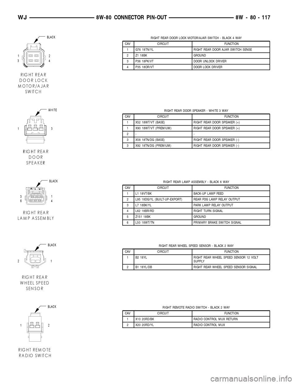
RIGHT REAR DOOR LOCK MOTOR/AJAR SWITCH - BLACK 4 WAY
CAV CIRCUIT FUNCTION
1 G76 18TN/YL RIGHT REAR DOOR AJAR SWITCH SENSE
2 Z1 18BK GROUND
3 P36 18PK/VT DOOR UNLOCK DRIVER
4 P35 18OR/VT DOOR LOCK DRIVER
RIGHT REAR DOOR SPEAKER - WHITE 3 WAY
CAV CIRCUIT FUNCTION
1 X52 18WT/VT (BASE) RIGHT REAR DOOR SPEAKER (+)
1 X90 18WT/VT (PREMIUM) RIGHT REAR DOOR SPEAKER (+)
2- -
3 X58 18TN/DG (BASE) RIGHT REAR DOOR SPEAKER (-)
3 X92 18TN/DG (PREMIUM) RIGHT REAR DOOR SPEAKER (-)
RIGHT REAR LAMP ASSEMBLY - BLACK 6 WAY
CAV CIRCUIT FUNCTION
1 L1 18VT/BK BACK-UP LAMP FEED
2 L95 18DG/YL (BUILT-UP-EXPORT) REAR FOG LAMP RELAY OUTPUT
3 L7 18BK/YL PARK LAMP RELAY OUTPUT
4 L62 18BR/RD RIGHT TURN SIGNAL
5 Z151 18BK GROUND
6 L50 18WT/TN PRIMARY BRAKE SWITCH SIGNAL
RIGHT REAR WHEEL SPEED SENSOR - BLACK 2 WAY
CAV CIRCUIT FUNCTION
1 B2 18YL RIGHT REAR WHEEL SPEED SENSOR 12 VOLT
SUPPLY
2 B1 18YL/DB RIGHT REAR WHEEL SPEED SENSOR SIGNAL
RIGHT REMOTE RADIO SWITCH - BLACK 2 WAY
CAV CIRCUIT FUNCTION
1 X10 20RD/BK RADIO CONTROL MUX RETURN
2 X20 20RD/YL RADIO CONTROL MUX
WJ8W-80 CONNECTOR PIN-OUT 8W - 80 - 117
Page 1181 of 2199
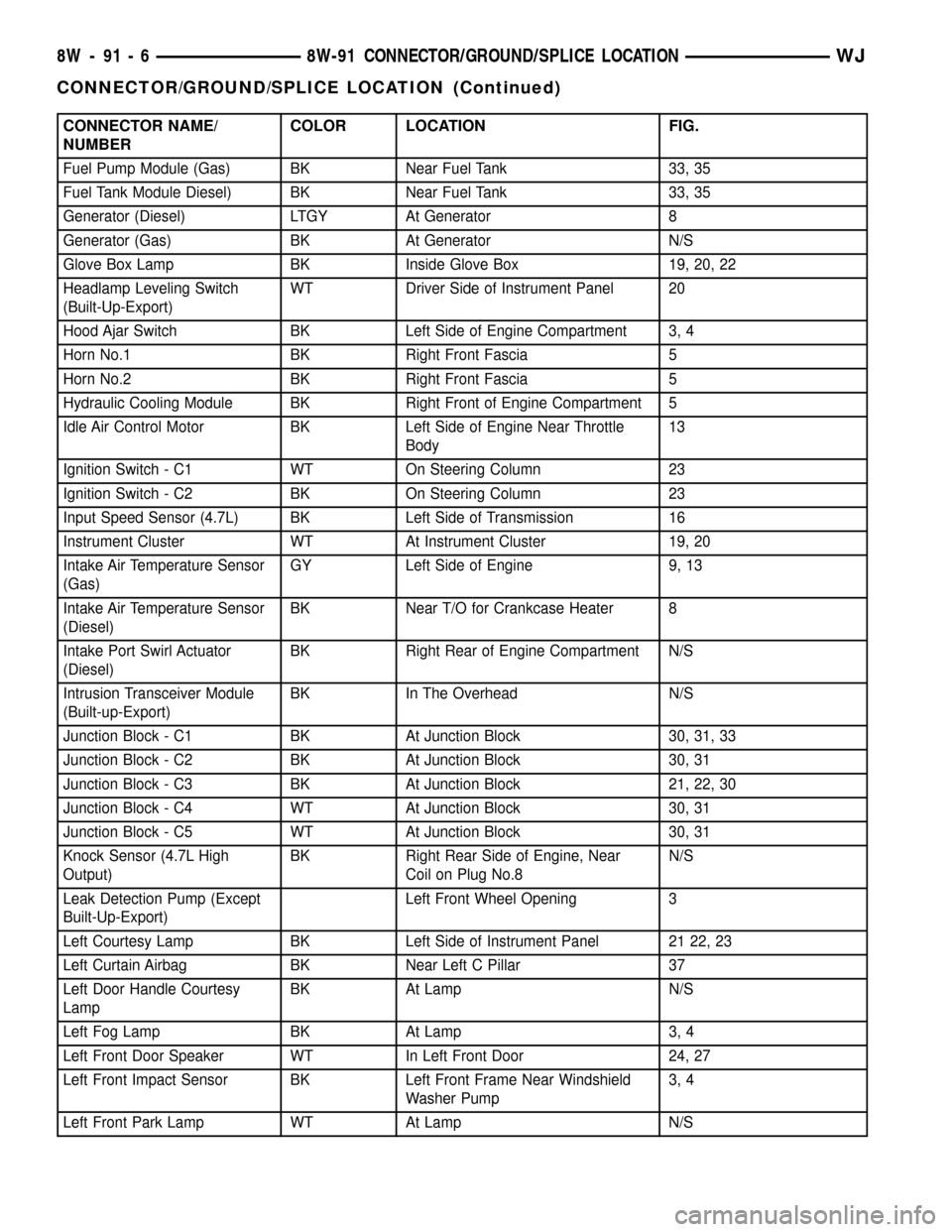
CONNECTOR NAME/
NUMBERCOLOR LOCATION FIG.
Fuel Pump Module (Gas) BK Near Fuel Tank 33, 35
Fuel Tank Module Diesel) BK Near Fuel Tank 33, 35
Generator (Diesel) LTGY At Generator 8
Generator (Gas) BK At Generator N/S
Glove Box Lamp BK Inside Glove Box 19, 20, 22
Headlamp Leveling Switch
(Built-Up-Export)WT Driver Side of Instrument Panel 20
Hood Ajar Switch BK Left Side of Engine Compartment 3, 4
Horn No.1 BK Right Front Fascia 5
Horn No.2 BK Right Front Fascia 5
Hydraulic Cooling Module BK Right Front of Engine Compartment 5
Idle Air Control Motor BK Left Side of Engine Near Throttle
Body13
Ignition Switch - C1 WT On Steering Column 23
Ignition Switch - C2 BK On Steering Column 23
Input Speed Sensor (4.7L) BK Left Side of Transmission 16
Instrument Cluster WT At Instrument Cluster 19, 20
Intake Air Temperature Sensor
(Gas)GY Left Side of Engine 9, 13
Intake Air Temperature Sensor
(Diesel)BK Near T/O for Crankcase Heater 8
Intake Port Swirl Actuator
(Diesel)BK Right Rear of Engine Compartment N/S
Intrusion Transceiver Module
(Built-up-Export)BK In The Overhead N/S
Junction Block - C1 BK At Junction Block 30, 31, 33
Junction Block - C2 BK At Junction Block 30, 31
Junction Block - C3 BK At Junction Block 21, 22, 30
Junction Block - C4 WT At Junction Block 30, 31
Junction Block - C5 WT At Junction Block 30, 31
Knock Sensor (4.7L High
Output)BK Right Rear Side of Engine, Near
Coil on Plug No.8N/S
Leak Detection Pump (Except
Built-Up-Export)Left Front Wheel Opening 3
Left Courtesy Lamp BK Left Side of Instrument Panel 21 22, 23
Left Curtain Airbag BK Near Left C Pillar 37
Left Door Handle Courtesy
LampBK At Lamp N/S
Left Fog Lamp BK At Lamp 3, 4
Left Front Door Speaker WT In Left Front Door 24, 27
Left Front Impact Sensor BK Left Front Frame Near Windshield
Washer Pump3, 4
Left Front Park Lamp WT At Lamp N/S
8W - 91 - 6 8W-91 CONNECTOR/GROUND/SPLICE LOCATIONWJ
CONNECTOR/GROUND/SPLICE LOCATION (Continued)
Page 1184 of 2199
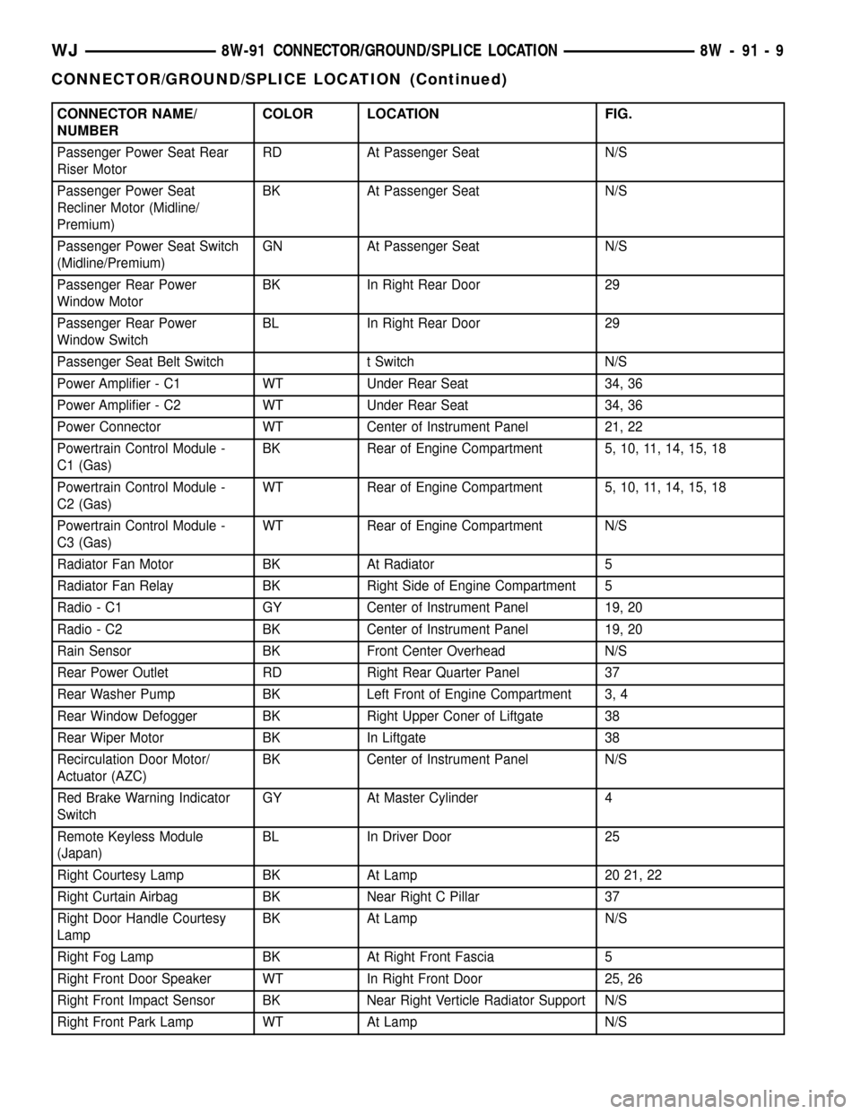
CONNECTOR NAME/
NUMBERCOLOR LOCATION FIG.
Passenger Power Seat Rear
Riser MotorRD At Passenger Seat N/S
Passenger Power Seat
Recliner Motor (Midline/
Premium)BK At Passenger Seat N/S
Passenger Power Seat Switch
(Midline/Premium)GN At Passenger Seat N/S
Passenger Rear Power
Window MotorBK In Right Rear Door 29
Passenger Rear Power
Window SwitchBL In Right Rear Door 29
Passenger Seat Belt Switch t Switch N/S
Power Amplifier - C1 WT Under Rear Seat 34, 36
Power Amplifier - C2 WT Under Rear Seat 34, 36
Power Connector WT Center of Instrument Panel 21, 22
Powertrain Control Module -
C1 (Gas)BK Rear of Engine Compartment 5, 10, 11, 14, 15, 18
Powertrain Control Module -
C2 (Gas)WT Rear of Engine Compartment 5, 10, 11, 14, 15, 18
Powertrain Control Module -
C3 (Gas)WT Rear of Engine Compartment N/S
Radiator Fan Motor BK At Radiator 5
Radiator Fan Relay BK Right Side of Engine Compartment 5
Radio - C1 GY Center of Instrument Panel 19, 20
Radio - C2 BK Center of Instrument Panel 19, 20
Rain Sensor BK Front Center Overhead N/S
Rear Power Outlet RD Right Rear Quarter Panel 37
Rear Washer Pump BK Left Front of Engine Compartment 3, 4
Rear Window Defogger BK Right Upper Coner of Liftgate 38
Rear Wiper Motor BK In Liftgate 38
Recirculation Door Motor/
Actuator (AZC)BK Center of Instrument Panel N/S
Red Brake Warning Indicator
SwitchGY At Master Cylinder 4
Remote Keyless Module
(Japan)BL In Driver Door 25
Right Courtesy Lamp BK At Lamp 20 21, 22
Right Curtain Airbag BK Near Right C Pillar 37
Right Door Handle Courtesy
LampBK At Lamp N/S
Right Fog Lamp BK At Right Front Fascia 5
Right Front Door Speaker WT In Right Front Door 25, 26
Right Front Impact Sensor BK Near Right Verticle Radiator Support N/S
Right Front Park Lamp WT At Lamp N/S
WJ8W-91 CONNECTOR/GROUND/SPLICE LOCATION 8W - 91 - 9
CONNECTOR/GROUND/SPLICE LOCATION (Continued)
Page 1191 of 2199
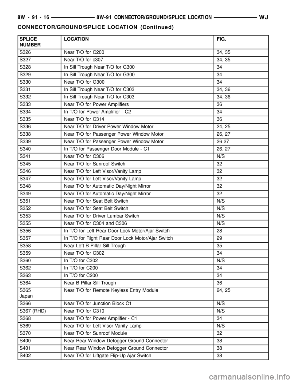
SPLICE
NUMBERLOCATION FIG.
S326 Near T/O for C200 34, 35
S327 Near T/O for c307 34, 35
S328 In Sill Trough Near T/O for G300 34
S329 In Sill Trough Near T/O for G300 34
S330 Near T/O for G300 34
S331 In Sill Trough Near T/O for C303 34, 36
S332 In Sill Trough Near T/O for C303 34, 36
S333 Near T/O for Power Amplifiers 36
S334 In T/O for Power Amplifier - C2 34
S335 Near T/O for C314 36
S336 Near T/O for Driver Power Window Motor 24, 25
S338 Near T/O for Passenger Power Window Motor 26, 27
S339 Near T/O for Passenger Power Window Motor 26 27
S340 In T/O for Passenger Door Module - C1 26, 27
S341 Near T/O for C306 N/S
S345 Near T/O for Sunroof Switch 32
S346 Near T/O for Left Visor/Vanity Lamp 32
S347 Near T/O for Left Visor/Vanity Lamp 32
S348 Near T/O for Automatic Day/Night Mirror 32
S349 Near T/O for Automatic Day/Night Mirror 32
S351 Near T/O for Seat Belt Switch N/S
S352 Near T/O for Seat Belt Switch N/S
S353 Near T/O for Driver Lumbar Switch N/S
S355 Near T/O for C304 and C306 N/S
S356 In T/O for Left Rear Door Lock Motor/Ajar Switch 28
S357 In T/O for Right Rear Door Lock Motor/Ajar Switch 29
S358 Near Left B Pillar Sill Trough 35
S359 Near T/O for C302 34
S360 In T/O for C302 N/S
S362 In T/O for C200 34
S363 In T/O for C200 34
S364 Near B Pillar Sill Trough 36
S365
JapanNear T/O for Remote Keyless Entry Module 24, 25
S366 Near T/O for Junction Block C1 N/S
S367 (RHD) Near T/O for C310 N/S
S368 Near T/O for Power Amplifier - C1 34
S369 Near T/O for Left Visor Vanity Lamp N/S
S370 Near T/O for Sunroof Module 32
S400 Near Rear Window Defogger Ground Connector 38
S401 Near Rear Window Defogger Ground Connector 38
S402 Near T/O for Liftgate Flip-Up Ajar Switch 38
8W - 91 - 16 8W-91 CONNECTOR/GROUND/SPLICE LOCATIONWJ
CONNECTOR/GROUND/SPLICE LOCATION (Continued)
Page 1412 of 2199
FRAME & BUMPERS
TABLE OF CONTENTS
page page
FRONT ABSORBER
REMOVAL.............................1
INSTALLATION..........................1
FRONT FASCIA
REMOVAL.............................1
INSTALLATION..........................1
REAR ABSORBER
REMOVAL.............................2
INSTALLATION..........................2
REAR FASCIA
REMOVAL.............................2
INSTALLATION..........................4
FRAME
SPECIFICATIONS
SPECIFICATIONS - TORQUE.............4
FRAME DIMENSIONS...................4
FRONT SKID PLATE
REMOVAL.............................7INSTALLATION..........................7
FRONT TOW HOOK
REMOVAL.............................7
INSTALLATION..........................7
FUEL TANK SKID PLATE
DESCRIPTION..........................7
REAR TOW HOOK
REMOVAL.............................7
INSTALLATION..........................7
TRAILER HITCH
REMOVAL.............................8
INSTALLATION..........................8
TRANSFER CASE SKID PLATE
REMOVAL.............................8
INSTALLATION..........................8
FRONT ABSORBER
REMOVAL
(1) Remove front fascia, refer to (Refer to 13 -
FRAMES & BUMPERS/BUMPERS/FRONT FASCIA
- REMOVAL).
(2) Remove the retainer attaching the absorber to
the fascia.
(3) Separate the absorber from the fascia.
INSTALLATION
(1) Position the absorber on the fascia.
(2) Install the retainer attaching the absorber to
the fascia.
(3) Install front fascia. Refer to (Refer to 13 -
FRAMES & BUMPERS/BUMPERS/FRONT FASCIA
- INSTALLATION).
FRONT FASCIA
REMOVAL
(1) Raise and support vehicle.
(2) Turn front wheels to access rivets and remove
plastic rivets attaching fascia to wheel liner.
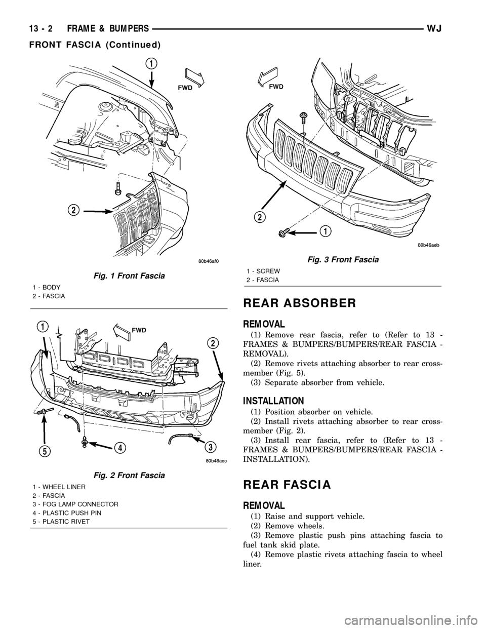
(3) Remove bolts attaching fascia to fender (Fig. 1).(4) Remove plastic push pin fasteners attaching
front fascia to lower radiator crossmember splash
shield (Fig. 2).
(5) Disengage fog lamp connectors, if equipped.
(6) Remove screws attaching fascia/grille to upper
radiator crossmember (Fig. 3).
(7) Slide fascia forward to separate from vehicle.
INSTALLATION
(1) Slide fascia onto vehicle engaging fascia with
tabs on bottom of front fenders.
(2) Install screws attaching fascia/grille to upper
radiator crossmember (Fig. 3).
(3) Install bolts attaching fascia to fender (Fig. 1).
(4) Engage fog lamp connectors, if equipped.
(5) Install plastic rivets attaching fascia to wheel
liner.
(6) Install plastic push pin fasteners attaching
front fascia to lower radiator crossmember splash
shield (Fig. 2).
(7) Remove supports and lower vehicle.
WJFRAME & BUMPERS 13 - 1
Page 1413 of 2199
REAR ABSORBER
REMOVAL
(1) Remove rear fascia, refer to (Refer to 13 -
FRAMES & BUMPERS/BUMPERS/REAR FASCIA -
REMOVAL).
(2) Remove rivets attaching absorber to rear cross-
member (Fig. 5).
(3) Separate absorber from vehicle.
INSTALLATION
(1) Position absorber on vehicle.
(2) Install rivets attaching absorber to rear cross-
member (Fig. 2).
(3) Install rear fascia, refer to (Refer to 13 -
FRAMES & BUMPERS/BUMPERS/REAR FASCIA -
INSTALLATION).
REAR FASCIA
REMOVAL
(1) Raise and support vehicle.
(2) Remove wheels.
(3) Remove plastic push pins attaching fascia to
fuel tank skid plate.
(4) Remove plastic rivets attaching fascia to wheel
liner.
Fig. 1 Front Fascia
1 - BODY
2 - FASCIA
Fig. 2 Front Fascia
1 - WHEEL LINER
2 - FASCIA
3 - FOG LAMP CONNECTOR
4 - PLASTIC PUSH PIN
5 - PLASTIC RIVET
Fig. 3 Front Fascia
1 - SCREW
2 - FASCIA
13 - 2 FRAME & BUMPERSWJ
FRONT FASCIA (Continued)