2003 JEEP GRAND CHEROKEE Engine 2.7
[x] Cancel search: Engine 2.7Page 12 of 2199

LUBRICATION & MAINTENANCE
TABLE OF CONTENTS
page page
LUBRICATION & MAINTENANCE
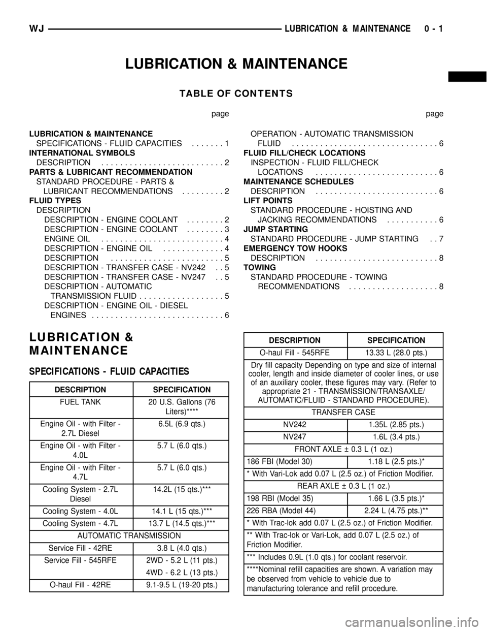
SPECIFICATIONS - FLUID CAPACITIES.......1
INTERNATIONAL SYMBOLS
DESCRIPTION..........................2
PARTS & LUBRICANT RECOMMENDATION
STANDARD PROCEDURE - PARTS &
LUBRICANT RECOMMENDATIONS.........2
FLUID TYPES
DESCRIPTION
DESCRIPTION - ENGINE COOLANT........2
DESCRIPTION - ENGINE COOLANT........3
ENGINE OIL..........................4
DESCRIPTION - ENGINE OIL.............4
DESCRIPTION........................5
DESCRIPTION - TRANSFER CASE - NV242 . . 5
DESCRIPTION - TRANSFER CASE - NV247 . . 5
DESCRIPTION - AUTOMATIC
TRANSMISSION FLUID..................5
DESCRIPTION - ENGINE OIL - DIESEL
ENGINES............................6OPERATION - AUTOMATIC TRANSMISSION
FLUID...............................6
FLUID FILL/CHECK LOCATIONS
INSPECTION - FLUID FILL/CHECK
LOCATIONS..........................6
MAINTENANCE SCHEDULES
DESCRIPTION..........................6
LIFT POINTS
STANDARD PROCEDURE - HOISTING AND
JACKING RECOMMENDATIONS...........6
JUMP STARTING
STANDARD PROCEDURE - JUMP STARTING . . 7
EMERGENCY TOW HOOKS
DESCRIPTION..........................8
TOWING
STANDARD PROCEDURE - TOWING
RECOMMENDATIONS...................8
LUBRICATION &
MAINTENANCE
SPECIFICATIONS - FLUID CAPACITIES
DESCRIPTION SPECIFICATION
FUEL TANK 20 U.S. Gallons (76
Liters)****
Engine Oil - with Filter -
2.7L Diesel6.5L (6.9 qts.)
Engine Oil - with Filter -
4.0L5.7 L (6.0 qts.)
Engine Oil - with Filter -
4.7L5.7 L (6.0 qts.)
Cooling System - 2.7L
Diesel14.2L (15 qts.)***
Cooling System - 4.0L 14.1 L (15 qts.)***
Cooling System - 4.7L 13.7 L (14.5 qts.)***
AUTOMATIC TRANSMISSION
Service Fill - 42RE 3.8 L (4.0 qts.)
Service Fill - 545RFE 2WD - 5.2 L (11 pts.)
4WD - 6.2 L (13 pts.)
O-haul Fill - 42RE 9.1-9.5 L (19-20 pts.)
DESCRIPTION SPECIFICATION
O-haul Fill - 545RFE 13.33 L (28.0 pts.)
Dry fill capacity Depending on type and size of internal
cooler, length and inside diameter of cooler lines, or use
of an auxiliary cooler, these figures may vary. (Refer to
appropriate 21 - TRANSMISSION/TRANSAXLE/
AUTOMATIC/FLUID - STANDARD PROCEDURE).
TRANSFER CASE
NV242 1.35L (2.85 pts.)
NV247 1.6L (3.4 pts.)
FRONT AXLE 0.3 L (1 oz.)
186 FBI (Model 30) 1.18 L (2.5 pts.)*
* With Vari-Lok add 0.07 L (2.5 oz.) of Friction Modifier.
REAR AXLE 0.3 L (1 oz.)
198 RBI (Model 35) 1.66 L (3.5 pts.)*
226 RBA (Model 44) 2.24 L (4.75 pts.)**
* With Trac-lok add 0.07 L (2.5 oz.) of Friction Modifier.
** With Trac-lok or Vari-Lok, add 0.07 L (2.5 oz.) of
Friction Modifier.
*** Includes 0.9L (1.0 qts.) for coolant reservoir.
****Nominal refill capacities are shown. A variation may
be observed from vehicle to vehicle due to
manufacturing tolerance and refill procedure.
WJLUBRICATION & MAINTENANCE 0 - 1
Page 1199 of 2199

Fig. 7 2.7 LITER DIESEL ENGINE LEFT SIDE
8W - 91 - 24 8W-91 CONNECTOR/GROUND/SPLICE LOCATIONWJ
CONNECTOR/GROUND/SPLICE LOCATION (Continued)
Page 1200 of 2199

Fig. 8 2.7 LITER DIESEL ENGINE RIGHT SIDE
WJ8W-91 CONNECTOR/GROUND/SPLICE LOCATION 8W - 91 - 25
CONNECTOR/GROUND/SPLICE LOCATION (Continued)
Page 1303 of 2199

TIMING BELT/CHAIN AND
SPROCKETS
REMOVAL
(1) Disconnect negative cable from battery.
(2) Remove the fan and shroud (Refer to 7 -
COOLING/ENGINE/RADIATOR FAN - REMOVAL).
(3) Remove the serpentine drive belt (Refer to 7 -
COOLING/ACCESSORY DRIVE/DRIVE BELTS -
REMOVAL).
(4) Remove the crankshaft vibration damper (Refer
to 9 - ENGINE/ENGINE BLOCK/VIBRATION
DAMPER - REMOVAL).
(5) Remove the timing case cover (Refer to 9 -
ENGINE/VALVE TIMING/TIMING BELT / CHAIN
COVER(S) - REMOVAL).
(6) Rotate crankshaft until the ª0º timing mark is
closest to and on the center line with camshaft
sprocket timing mark (Fig. 88).
(7) Remove the oil slinger from the crankshaft.
(8) Remove the camshaft sprocket bolt and washer
(Fig. 89).
(9) Remove the crankshaft sprocket, camshaft
sprocket and timing chain as an assembly.
(10) Installation of the timing chain with the tim-
ing marks on the crankshaft and camshaft sprockets
properly aligned ensures correct valve timing. A worn
or stretched timing chain will adversely affect valvetiming. If the timing chain deflects more than 12.7
mm (1/2 inch) replace it.
INSTALLATION
Assemble the timing chain, crankshaft sprocket
and camshaft sprocket with the timing marks
aligned (Fig. 88).
(1) Apply MopartSilicone Rubber Adhesive Seal-
ant to the keyway in the crankshaft and insert the
key. With the key in the keyway on the crankshaft,
install the assembly on the crankshaft and camshaft.
(2)
Install the camshaft sprocket bolt and washer
(Fig. 89). Tighten the bolt to 68 N´m (50 ft. lbs.) torque.
(3) To verify correct installation of the timing
chain, rotate the crankshaft 2 revolutions. The cam-
shaft and crankshaft sprocket timing mark should
align (Fig. 88).
(4) Install the crankshaft oil slinger.
(5) Replace the oil seal in the timing case cover
(Refer to 9 - ENGINE/ENGINE BLOCK/CRANK-
SHAFT OIL SEAL - FRONT - REMOVAL).
(6) Install the timing case cover and gasket (Refer
to 9 - ENGINE/VALVE TIMING/TIMING BELT /
CHAIN COVER(S) - INSTALLATION).
(7) With the key installed in the crankshaft key-
way, install the vibration damper (Refer to 9 -
ENGINE/ENGINE BLOCK/VIBRATION DAMPER -
INSTALLATION).
(8) Install the serpentine drive belt (Refer to 7 -
COOLING/ACCESSORY DRIVE/DRIVE BELTS -
INSTALLATION).
(9) Install the fan, hub assembly and shroud
(Refer to 7 - COOLING/ENGINE/RADIATOR FAN -
INSTALLATION).
(10) Connect negative cable to battery.
Fig. 88 CrankshaftÐCamshaft Alignment
1 - CAMSHAFT SPROCKET
2 - TIMING MARKS
3 - CRANKSHAFT SPROCKET
Fig. 89 Camshaft Sprocket and Thrust Plate
1 - CAMSHAFT
2 - CAMSHAFT SPROCKET W/INTEGRAL KEY
3 - BOLT AND WASHER
4 - THRUST PLATE
9 - 60 ENGINE - 4.0LWJ
Page 1524 of 2199

IDENTIFICATION
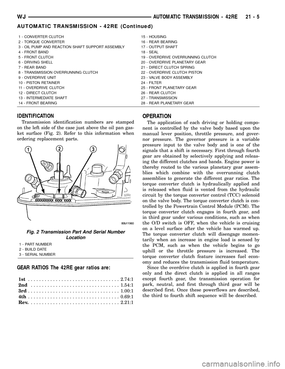
Transmission identification numbers are stamped
on the left side of the case just above the oil pan gas-
ket surface (Fig. 2). Refer to this information when
ordering replacement parts.
GEAR RATIOS The 42RE gear ratios are:
1st.................................2.74:1
2nd................................1.54:1
3rd.................................1.00:1
4th.................................0.69:1
Rev.................................2.21:1
OPERATION
The application of each driving or holding compo-
nent is controlled by the valve body based upon the
manual lever position, throttle pressure, and gover-
nor pressure. The governor pressure is a variable
pressure input to the valve body and is one of the
signals that a shift is necessary. First through fourth
gear are obtained by selectively applying and releas-
ing the different clutches and bands. Engine power is
thereby routed to the various planetary gear assem-
blies which combine with the overrunning clutch
assemblies to generate the different gear ratios. The
torque converter clutch is hydraulically applied and
is released when fluid is vented from the hydraulic
circuit by the torque converter control (TCC) solenoid
on the valve body. The torque converter clutch is con-
trolled by the Powertrain Control Module (PCM). The
torque converter clutch engages in fourth gear, and
in third gear under various conditions, such as when
the O/D switch is OFF, when the vehicle is cruising
on a level surface after the vehicle has warmed up.
The torque converter clutch will disengage momen-
tarily when an increase in engine load is sensed by
the PCM, such as when the vehicle begins to go
uphill or the throttle pressure is increased. The
torque converter clutch feature increases fuel econ-
omy and reduces the transmission fluid temperature.
Since the overdrive clutch is applied in fourth gear
only and the direct clutch is applied in all ranges
except fourth gear, the transmission operation for
park, neutral, and first through third gear will be
described first. Once these powerflows are described,
the third to fourth shift sequence will be described.
1 - CONVERTER CLUTCH 15 - HOUSING
2 - TORQUE CONVERTER 16 - REAR BEARING
3 - OIL PUMP AND REACTION SHAFT SUPPORT ASSEMBLY 17 - OUTPUT SHAFT
4 - FRONT BAND 18 - SEAL
5 - FRONT CLUTCH 19 - OVERDRIVE OVERRUNNING CLUTCH
6 - DRIVING SHELL 20 - OVERDRIVE PLANETARY GEAR
7 - REAR BAND 21 - DIRECT CLUTCH SPRING
8 - TRANSMISSION OVERRUNNING CLUTCH 22 - OVERDRIVE CLUTCH PISTON
9 - OVERDRIVE UNIT 23 - VALVE BODY ASSEMBLY
10 - PISTON RETAINER 24 - FILTER
11 - OVERDRIVE CLUTCH 25 - FRONT PLANETARY GEAR
12 - DIRECT CLUTCH 26 - REAR CLUTCH
13 - INTERMEDIATE SHAFT 27 - TRANSMISSION
14 - FRONT BEARING 28 - REAR PLANETARY GEAR
Fig. 2 Transmission Part And Serial Number
Location
1 - PART NUMBER
2 - BUILD DATE
3 - SERIAL NUMBER
WJAUTOMATIC TRANSMISSION - 42RE 21 - 5
AUTOMATIC TRANSMISSION - 42RE (Continued)
Page 2085 of 2199

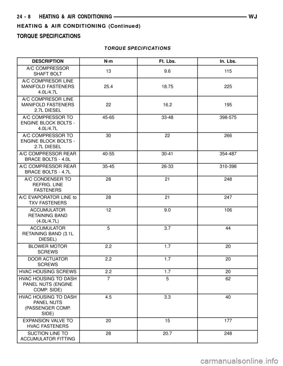
TORQUE SPECIFICATIONS
TORQUE SPECIFICATIONS
DESCRIPTION N´m Ft. Lbs. In. Lbs.
A/C COMPRESSOR
SHAFT BOLT13 9.6 115
A/C COMPRESOR LINE
MANIFOLD FASTENERS
4.0L/4.7L25.4 18.75 225
A/C COMPRESOR LINE
MANIFOLD FASTENERS
2.7L DIESEL22 16.2 195
A/C COMPRESSOR TO
ENGINE BLOCK BOLTS -
4.0L/4.7L45-65 33-48 398-575
A/C COMPRESSOR TO
ENGINE BLOCK BOLTS -
2.7L DIESEL30 22 266
A/C COMPRESSOR REAR
BRACE BOLTS - 4.0L40-55 30-41 354-487
A/C COMPRESSOR REAR
BRACE BOLTS - 4.7L35-45 26-33 310-398
A/C CONDENSER TO
REFRIG. LINE
FASTENERS28 21 248
A/C EVAPORATOR LINE to
TXV FASTENERS28 21 247
ACCUMULATOR
RETAINING BAND
(4.0L/4.7L)12 9.0 106
ACCUMULATOR
RETAINING BAND (3.1L
DIESEL)5 3.7 44
BLOWER MOTOR
SCREWS2.2 1.7 20
DOOR ACTUATOR
SCREWS2.2 1.7 20
HVAC HOUSING SCREWS 2.2 1.7 20
HVAC HOUSING TO DASH
PANEL NUTS (ENGINE
COMP. SIDE)75 62
HVAC HOUSING TO DASH
PANEL NUTS
(PASSENGER COMP.
SIDE)4.5 3.3 40
EXPANSION VALVE TO
HVAC FASTENERS20 15 177
SUCTION LINE TO
ACCUMULATOR FITTING28 20.7 248
24 - 8 HEATING & AIR CONDITIONINGWJ
HEATING & AIR CONDITIONING (Continued)
Page 2140 of 2199

(11) Remove the bolts that secure the upper con-
denser and transmission cooler.
(12) Carefully lift the condenser out of the vehicle.
INSTALLATION
WARNING: REVIEW THE WARNINGS AND CAU-
TIONS IN THE FRONT OF THIS SECTION BEFORE
PERFORMING THE FOLLOWING OPERATION.
(Refer to 24 - HEATING & AIR CONDITIONING/
PLUMBING - WARNING) (Refer to 24 - HEATING &
AIR CONDITIONING/PLUMBING - CAUTION)
Any kinks or sharp bends in the refrigerant plumb-
ing will reduce the capacity of the entire air condi-
tioning system. Kinks and sharp bends reduce the
flow of refrigerant in the system. A good rule for the
flexible hose refrigerant lines is to keep the radius of
all bends at least ten times the diameter of the hose.
In addition, the flexible hose refrigerant lines should
be routed so they are at least 80 millimeters (3
inches) from the exhaust manifold.
High pressures are produced in the refrigerant sys-
tem when the air conditioning compressor is operat-
ing. Extreme care must be exercised to make sure
that each of the refrigerant system connections is
pressure-tight and leak free. It is a good practice to
inspect all flexible hose refrigerant lines at least once
a year to make sure they are in good condition and
properly routed.
CAUTION: Before removing the condenser, note the
location of each of the radiator and condenser air
seals. These seals are used to direct air through the
condenser and radiator. The air seals must be rein-
stalled in their proper locations in order for the air
conditioning and engine cooling systems to per-
form as designed.
(1) Carefully position the condenser in the vehicle.
(2) Install the bolts that secure the upper con-
denser and transmission cooler.
(3) Remove the tape or plugs from the refrigerant
line fittings on the condenser inlet and the discharge
line. Connect the discharge line to the condenser
inlet. Tighten the retaining nut to 28 N´m (250 in.
lbs.).
(4) Remove the tape or plugs from the refrigerant
line fittings on the condenser outlet and the liquid
line. Connect the liquid line to the condenser outlet.
Tighten the retaining nut to 28 N´m (250 in. lbs.).
(5) Install the headlamp mounting module and
front fascia. Refer to Body for the procedure.
(6) Install the engine air filter inlet duct.
(7) Install the bolts that secure the radiator to the
upper crossmember.(8) Install the nuts that secure the hood latch and
brace to the upper crossmember.
(9) Install the headlamps in their mounts.
(10) Install the screws attaching the grille and
headlamp mounting module to the upper crossmem-
ber of the vehicle. Refer to Body for this and further
steps in the procedure.
(11) Evacuate and Recharge the refrigerant sys-
tem. (Refer to 24 - HEATING & AIR CONDITION-
ING/PLUMBING - STANDARD PROCEDURE -
REFRIGERANT SYSTEM EVACUATE) (Refer to 24 -
HEATING & AIR CONDITIONING/PLUMBING -
STANDARD PROCEDURE - REFRIGERANT SYS-
TEM CHARGE)
(12) Connect the battery negative cable.
NOTE: If the condenser is replaced, add 30 millili-
ters (1 fluid ounce) of refrigerant oil to the refriger-
ant system. Use only refrigerant oil of the type
recommended for the compressor in the vehicle.
(Refer to 24 - HEATING & AIR CONDITIONING/
PLUMBING/REFRIGERANT OIL - DESCRIPTION)
A/C DISCHARGE LINE
REMOVAL
REMOVAL - 2.7L TURBO DIESEL
WARNING: REVIEW THE WARNINGS AND CAU-
TIONS IN THE FRONT OF THIS SECTION BEFORE
PERFORMING THE FOLLOWING OPERATION.
(Refer to 24 - HEATING & AIR CONDITIONING/
PLUMBING - WARNING) (Refer to 24 - HEATING &
AIR CONDITIONING/PLUMBING - CAUTION)
(1) Disconnect and isolate the negative battery
cable.
(2) Recover the refrigerant system. (Refer to 24 -
HEATING & AIR CONDITIONING/PLUMBING -
STANDARD PROCEDURE - REFRIGERANT
RECOVERY)
(3) Remove both headlamps from the vehicle. Refer
to Lamps/Lighting for the procedure.
(4) Remove the a/c high pressure transducer(Refer
to 24 - HEATING & AIR CONDITIONING/CON-
TROLS/A/C PRESSURE TRANSDUCER - REMOV-
AL).
(5) Remove the front fascia from the vehicle. Refer
to Front Fascia for the procedure (Fig. 7).
(6) Remove the refrigerant line retaining fastener
from the condenser inlet fitting. Remove the line and
cap the condenser inlet tube to prevent contamina-
tion of the system.
WJPLUMBING 24 - 63
A/C CONDENSER (Continued)