2003 JEEP GRAND CHEROKEE spec
[x] Cancel search: specPage 1453 of 2199
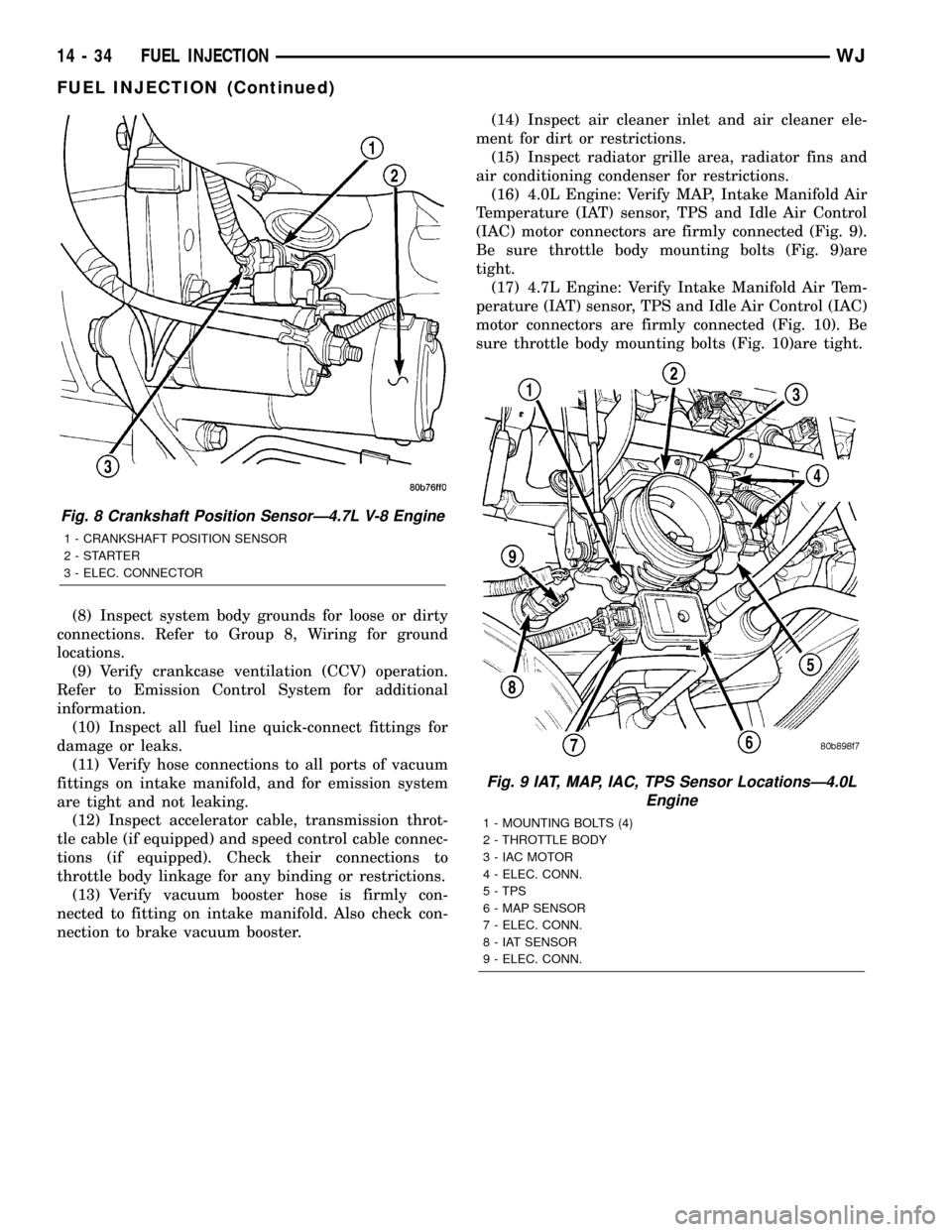
(8) Inspect system body grounds for loose or dirty
connections. Refer to Group 8, Wiring for ground
locations.
(9) Verify crankcase ventilation (CCV) operation.
Refer to Emission Control System for additional
information.
(10) Inspect all fuel line quick-connect fittings for
damage or leaks.
(11) Verify hose connections to all ports of vacuum
fittings on intake manifold, and for emission system
are tight and not leaking.
(12) Inspect accelerator cable, transmission throt-
tle cable (if equipped) and speed control cable connec-
tions (if equipped). Check their connections to
throttle body linkage for any binding or restrictions.
(13) Verify vacuum booster hose is firmly con-
nected to fitting on intake manifold. Also check con-
nection to brake vacuum booster.(14) Inspect air cleaner inlet and air cleaner ele-
ment for dirt or restrictions.
(15) Inspect radiator grille area, radiator fins and
air conditioning condenser for restrictions.
(16) 4.0L Engine: Verify MAP, Intake Manifold Air
Temperature (IAT) sensor, TPS and Idle Air Control
(IAC) motor connectors are firmly connected (Fig. 9).
Be sure throttle body mounting bolts (Fig. 9)are
tight.
(17) 4.7L Engine: Verify Intake Manifold Air Tem-
perature (IAT) sensor, TPS and Idle Air Control (IAC)
motor connectors are firmly connected (Fig. 10). Be
sure throttle body mounting bolts (Fig. 10)are tight.
Fig. 8 Crankshaft Position SensorÐ4.7L V-8 Engine
1 - CRANKSHAFT POSITION SENSOR
2-STARTER
3 - ELEC. CONNECTOR
Fig. 9 IAT, MAP, IAC, TPS Sensor LocationsÐ4.0L
Engine
1 - MOUNTING BOLTS (4)
2 - THROTTLE BODY
3 - IAC MOTOR
4 - ELEC. CONN.
5 - TPS
6 - MAP SENSOR
7 - ELEC. CONN.
8 - IAT SENSOR
9 - ELEC. CONN.
14 - 34 FUEL INJECTIONWJ
FUEL INJECTION (Continued)
Page 1454 of 2199
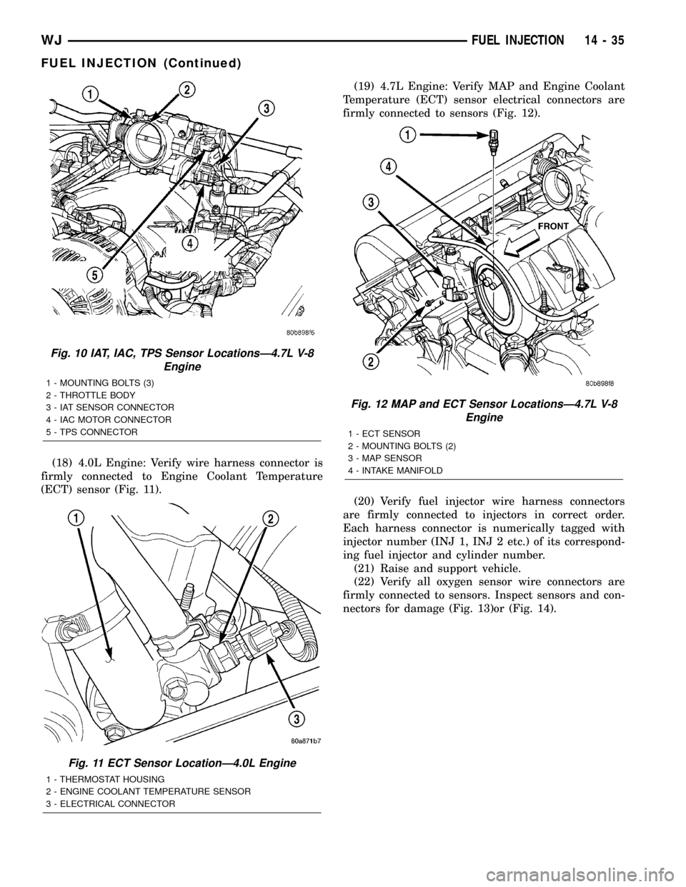
(18) 4.0L Engine: Verify wire harness connector is
firmly connected to Engine Coolant Temperature
(ECT) sensor (Fig. 11).(19) 4.7L Engine: Verify MAP and Engine Coolant
Temperature (ECT) sensor electrical connectors are
firmly connected to sensors (Fig. 12).
(20) Verify fuel injector wire harness connectors
are firmly connected to injectors in correct order.
Each harness connector is numerically tagged with
injector number (INJ 1, INJ 2 etc.) of its correspond-
ing fuel injector and cylinder number.
(21) Raise and support vehicle.
(22) Verify all oxygen sensor wire connectors are
firmly connected to sensors. Inspect sensors and con-
nectors for damage (Fig. 13)or (Fig. 14).
Fig. 10 IAT, IAC, TPS Sensor LocationsÐ4.7L V-8
Engine
1 - MOUNTING BOLTS (3)
2 - THROTTLE BODY
3 - IAT SENSOR CONNECTOR
4 - IAC MOTOR CONNECTOR
5 - TPS CONNECTOR
Fig. 11 ECT Sensor LocationÐ4.0L Engine
1 - THERMOSTAT HOUSING
2 - ENGINE COOLANT TEMPERATURE SENSOR
3 - ELECTRICAL CONNECTOR
Fig. 12 MAP and ECT Sensor LocationsÐ4.7L V-8
Engine
1 - ECT SENSOR
2 - MOUNTING BOLTS (2)
3 - MAP SENSOR
4 - INTAKE MANIFOLD
WJFUEL INJECTION 14 - 35
FUEL INJECTION (Continued)
Page 1457 of 2199

(23) Inspect for pinched or leaking fuel tubes/lines.
Inspect for pinched, cracked or leaking fuel hoses.
(24) Inspect for exhaust system restrictions such
as pinched exhaust pipes, collapsed muffler or
plugged catalytic convertor.
(25) If equipped with automatic transmission, ver-
ify electrical harness is firmly connected to park/neu-
tral switch and to transmission components.
(26) Verify fuel pump module pigtail harness elec-
trical connector (Fig. 15) is firmly connected to body
harness connector.
(27) Inspect fuel line harness (from fuel pump
module) at fuel filter/fuel pressure regulator (Fig. 15)
for chaffing, cracks or leaks.
(28) Verify battery cable and solenoid feed wire
connections to starter solenoid are tight and clean.
(29) Inspect for chaffed wires or wires rubbing up
against other components.
(30) Inspect for chaffed vacuum lines or lines rub-
bing up against other components.
Fig. 15 Fuel Filter/Fuel Pressure Regulator Location
1 - FUEL RETURN LINE
2 - FUEL SUPPLY LINE (TO FUEL RAIL)
3 - FUEL FILTER/FUEL PRESSURE REGULATOR
4 - FUEL PRESSURE LINE
5 - REAR AXLE
6 - ELEC. CONNECTOR
7 - EVAP LINE
14 - 38 FUEL INJECTIONWJ
FUEL INJECTION (Continued)
Page 1458 of 2199
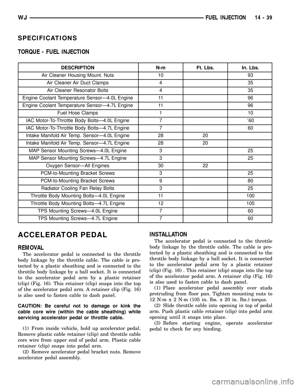
SPECIFICATIONS
TORQUE - FUEL INJECTION
DESCRIPTION N-m Ft. Lbs. In. Lbs.
Air Cleaner Housing Mount. Nuts 10 93
Air Cleaner Air Duct Clamps 4 35
Air Cleaner Resonator Bolts 4 35
Engine Coolant Temperature SensorÐ4.0L Engine 11 96
Engine Coolant Temperature SensorÐ4.7L Engine 11 96
Fuel Hose Clamps 1 10
IAC Motor-To-Throttle Body BoltsÐ4.0L Engine 7860
IAC Motor-To-Throttle Body BoltsÐ4.7L Engine 7 60
Intake Manifold Air Temp. SensorÐ4.0L Engine 28 20
Intake Manifold Air Temp. SensorÐ4.7L Engine 28 20
MAP Sensor Mounting ScrewsÐ4.0L Engine 3 25
MAP Sensor Mounting ScrewsÐ4.7L Engine 3 25
Oxygen SensorÐAll Engines 30 22
PCM-to-Mounting Bracket Screws 3 25
PCM-to-Mounting Bracket Screws 9 80
Radiator Cooling Fan Relay Bolts 3 25
Throttle Body Mounting BoltsÐ4.0L Engine 11 100
Throttle Body Mounting BoltsÐ4.7L Engine 12 105
TPS Mounting ScrewsÐ4.0L Engine 7 60
TPS Mounting ScrewsÐ4.7L Engine 7 60
ACCELERATOR PEDAL
REMOVAL
The accelerator pedal is connected to the throttle
body linkage by the throttle cable. The cable is pro-
tected by a plastic sheathing and is connected to the
throttle body linkage by a ball socket. It is connected
to the accelerator pedal arm by a plastic retainer
(clip) (Fig. 16). This retainer (clip) snaps into the top
of the accelerator pedal arm. A retainer clip (Fig. 16)
is also used to fasten cable to dash panel.
CAUTION: Be careful not to damage or kink the
cable core wire (within the cable sheathing) while
servicing accelerator pedal or throttle cable.
(1) From inside vehicle, hold up accelerator pedal.
Remove plastic cable retainer (clip) and throttle cable
core wire from upper end of pedal arm. Plastic cable
retainer (clip) snaps into pedal arm.
(2) Remove accelerator pedal bracket nuts. Remove
accelerator pedal assembly.
INSTALLATION
The accelerator pedal is connected to the throttle
body linkage by the throttle cable. The cable is pro-
tected by a plastic sheathing and is connected to the
throttle body linkage by a ball socket. It is connected
to the accelerator pedal arm by a plastic retainer
(clip) (Fig. 16) . This retainer (clip) snaps into the top
of the accelerator pedal arm. A retainer clip (Fig. 16)
is also used to fasten cable to dash panel.
(1) Place accelerator pedal assembly over studs
protruding from floor pan. Tighten mounting nuts to
12 N´m 2 N´m (105 in. lbs. 20 in. lbs.) torque.
(2) Slide throttle cable into opening in top of pedal
arm. Push plastic cable retainer (clip) into pedal arm
opening until it snaps into place.
(3) Before starting engine, operate accelerator
pedal to check for any binding.
WJFUEL INJECTION 14 - 39
Page 1462 of 2199

(5) Push sensor against flywheel/drive plate. With
sensor pushed against flywheel/drive plate, tighten
mounting bolt to 7 N´m (60 in. lbs.) torque.
(6) Route sensor wiring harness into wire shield.
(7) Connect sensor pigtail harness electrical con-
nector to main wiring harness.
INSTALLATION - 4.7L
(1) Clean out machined hole in engine block.
(2) Apply a small amount of engine oil to sensor
o-ring.
(3) Install sensor into engine block with a slight
rocking action. Do not twist sensor into position as
damage to o-ring may result.
CAUTION: Before tightening sensor mounting bolt,
be sure sensor is completely flush to cylinder
block. If sensor is not flush, damage to sensor
mounting tang may result.
(4) Install mounting bolt and tighten to 28 N´m
(21 ft. lbs.) torque.
(5) Connect electrical connector to sensor.
(6) Install starter motor. Refer to Starter Removal/
Installation.
FUEL INJECTOR
DESCRIPTION
A separate fuel injector (Fig. 24) is used for each
individual cylinder.
OPERATION
OPERATION
The fuel injectors are electrical solenoids. The
injector contains a pintle that closes off an orifice at
the nozzle end. When electric current is supplied to
the injector, the armature and needle move a short
distance against a spring, allowing fuel to flow out
the orifice. Because the fuel is under high pressure, a
fine spray is developed in the shape of a pencil
stream. The spraying action atomizes the fuel, add-
ing it to the air entering the combustion chamber.
The top (fuel entry) end of the injector (Fig. 24) is
attached into an opening on the fuel rail.
The nozzle (outlet) ends of the injectors are posi-
tioned into openings in the intake manifold just
above the intake valve ports of the cylinder head.
The engine wiring harness connector for each fuel
injector is equipped with an attached numerical tag
(INJ 1, INJ 2 etc.). This is used to identify each fuel
injector.
The injectors are electrically energized, individu-
ally and in a sequential order by the Powertrain Con-
trol Module (PCM). The PCM will adjust injector
pulse width by switching the ground path to each
individual injector on and off. Injector pulse width is
the period of time that the injector is energized. The
PCM will adjust injector pulse width based on vari-
ous inputs it receives.
Battery voltage is supplied to the injectors through
the ASD relay.
The PCM determines injector pulse width based on
various inputs.
OPERATION - PCM OUTPUT
The nozzle ends of the injectors are positioned into
openings in the intake manifold just above the intake
valve ports of the cylinder head. The engine wiring
harness connector for each fuel injector is equipped
with an attached numerical tag (INJ 1, INJ 2 etc.).
This is used to identify each fuel injector with its
respective cylinder number.
The injectors are energized individually in a
sequential order by the Powertrain Control Module
(PCM). The PCM will adjust injector pulse width by
switching the ground path to each individual injector
on and off. Injector pulse width is the period of time
that the injector is energized. The PCM will adjust
injector pulse width based on various inputs it
receives.
Battery voltage (12 volts +) is supplied to the injec-
tors through the ASD relay. The ASD relay will shut-
down the 12 volt power source to the fuel injectors if
the PCM senses the ignition is on, but the engine is
not running. This occurs after the engine has not
been running for approximately 1.8 seconds.
Fig. 24 Fuel InjectorÐ4.0L/4.7L Engines
1 - FUEL INJECTOR
2 - NOZZLE
3 - TOP (FUEL ENTRY)
WJFUEL INJECTION 14 - 43
CRANKSHAFT POSITION SENSOR (Continued)
Page 1479 of 2199
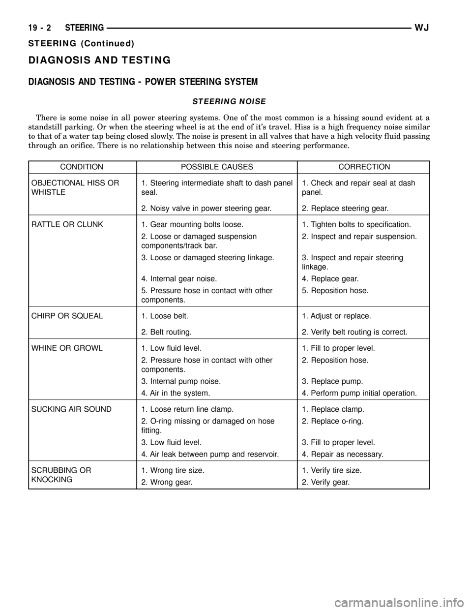
DIAGNOSIS AND TESTING
DIAGNOSIS AND TESTING - POWER STEERING SYSTEM
STEERING NOISE
There is some noise in all power steering systems. One of the most common is a hissing sound evident at a
standstill parking. Or when the steering wheel is at the end of it's travel. Hiss is a high frequency noise similar
to that of a water tap being closed slowly. The noise is present in all valves that have a high velocity fluid passing
through an orifice. There is no relationship between this noise and steering performance.
CONDITION POSSIBLE CAUSES CORRECTION
OBJECTIONAL HISS OR
WHISTLE1. Steering intermediate shaft to dash panel
seal.1. Check and repair seal at dash
panel.
2. Noisy valve in power steering gear. 2. Replace steering gear.
RATTLE OR CLUNK 1. Gear mounting bolts loose. 1. Tighten bolts to specification.
2. Loose or damaged suspension
components/track bar.2. Inspect and repair suspension.
3. Loose or damaged steering linkage. 3. Inspect and repair steering
linkage.
4. Internal gear noise. 4. Replace gear.
5. Pressure hose in contact with other
components.5. Reposition hose.
CHIRP OR SQUEAL 1. Loose belt. 1. Adjust or replace.
2. Belt routing. 2. Verify belt routing is correct.
WHINE OR GROWL 1. Low fluid level. 1. Fill to proper level.
2. Pressure hose in contact with other
components.2. Reposition hose.
3. Internal pump noise. 3. Replace pump.
4. Air in the system. 4. Perform pump initial operation.
SUCKING AIR SOUND 1. Loose return line clamp. 1. Replace clamp.
2. O-ring missing or damaged on hose
fitting.2. Replace o-ring.
3. Low fluid level. 3. Fill to proper level.
4. Air leak between pump and reservoir. 4. Repair as necessary.
SCRUBBING OR
KNOCKING1. Wrong tire size. 1. Verify tire size.
2. Wrong gear. 2. Verify gear.
19 - 2 STEERINGWJ
STEERING (Continued)
Page 1480 of 2199
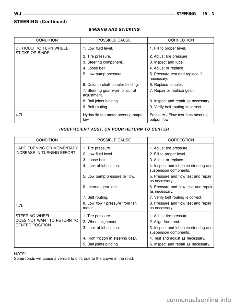
BINDING AND STICKING
CONDITION POSSIBLE CAUSE CORRECTION
DIFFICULT TO TURN WHEEL
STICKS OR BINDS1. Low fluid level. 1. Fill to proper level.
2. Tire pressure. 2. Adjust tire pressure.
3. Steering component. 3. Inspect and lube.
4. Loose belt. 4. Adjust or replace.
5. Low pump pressure. 5. Pressure test and replace if
necessary.
6. Column shaft coupler binding. 6. Replace coupler.
7. Steering gear worn or out of
adjustment.7. Repair or replace gear.
8. Ball joints binding. 8. Inspect and repair as necessary.
9. Belt routing. 9. Verify belt routing is correct.
4.7L Hydraulic fan motor steering output
lowPressure / Flow test fans steering
output flow
INSUFFICIENT ASST. OR POOR RETURN TO CENTER
CONDITION POSSIBLE CAUSE CORRECTION
HARD TURNING OR MOMENTARY
INCREASE IN TURNING EFFORT1. Tire pressure. 1. Adjust tire pressure.
2. Low fluid level. 2. Fill to proper level.
3. Loose belt. 3. Adjust or replace.
4. Lack of lubrication. 4. Inspect and lubricate steering and
suspension compnents.
5. Low pump pressure or flow. 5. Pressure and flow test and repair
as necessary.
6. Internal gear leak. 6. Pressure and flow test, and repair
as necessary.
7. Belt routing. 7. Verify belt routing is correct.
4.7L8. Low flow / pressure from fan
motor8. Pressure and flow test and repair
as necessary.
STEERING WHEEL
DOES NOT WANT TO RETURN TO
CENTER POSITION1. Tire pressure. 1. Adjust tire pressure.
2. Wheel alignment. 2. Align front end.
3. Lack of lubrication. 3. Inspect and lubricate steering and
suspension compnents.
4. High friction in steering gear. 4. Test and adjust as necessary.
5. Ball joints binding. 5. Inspect and repair as necessary.
NOTE:
Some roads will cause a vehicle to drift, due to the crown in the road.
WJSTEERING 19 - 3
STEERING (Continued)
Page 1481 of 2199
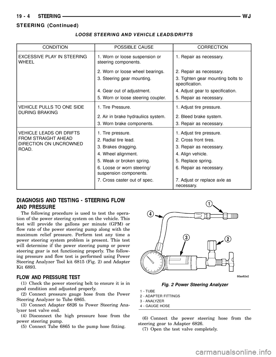
LOOSE STEERING AND VEHICLE LEADS/DRIFTS
CONDITION POSSIBLE CAUSE CORRECTION
EXCESSIVE PLAY IN STEERING
WHEEL1. Worn or loose suspension or
steering components.1. Repair as necessary.
2. Worn or loose wheel bearings. 2. Repair as necessary.
3. Steering gear mounting. 3. Tighten gear mounting bolts to
specification.
4. Gear out of adjustment. 4. Adjust gear to specification.
5. Worn or loose steering coupler. 5. Repair as necessary.
VEHICLE PULLS TO ONE SIDE
DURING BRAKING1. Tire Pressure. 1. Adjust tire pressure.
2. Air in brake hydrauliics system. 2. Bleed brake system.
3. Worn brake components. 3. Repair as necessary.
VEHICLE LEADS OR DRIFTS
FROM STRAIGHT AHEAD
DIRECTION ON UNCROWNED
ROAD.1. Tire pressure. 1. Adjust tire pressure.
2. Radial tire lead. 2. Cross front tires.
3. Brakes dragging. 3. Repair as necessary.
4. Wheel alignment. 4. Align vehicle.
5. Weak or broken spring. 5. Replace spring.
6. Loose or worn steering/
suspension components.6. Repair as necessary.
7. Cross caster out of spec. 7. Adjust or replace axle as
necessary.
DIAGNOSIS AND TESTING - STEERING FLOW
AND PRESSURE
The following procedure is used to test the opera-
tion of the power steering system on the vehicle. This
test will provide the gallons per minute (GPM) or
flow rate of the power steering pump along with the
maximum relief pressure. Perform test any time a
power steering system problem is present. This test
will determine if the power steering pump or power
steering gear is not functioning properly. The follow-
ing pressure and flow test is performed using Power
Steering Analyzer Tool kit 6815 (Fig. 2) and Adapter
Kit 6893.
FLOW AND PRESSURE TEST
(1) Check the power steering belt to ensure it is in
good condition and adjusted properly.
(2) Connect pressure gauge hose from the Power
Steering Analyzer to Tube 6865.
(3) Connect Adapter 6826 to Power Steering Ana-
lyzer test valve end.
(4) Disconnect the high pressure hose from the
power steering pump.
(5) Connect Tube 6865 to the pump hose fitting.(6) Connect the power steering hose from the
steering gear to Adapter 6826.
(7) Open the test valve completely.Fig. 2 Power Steering Analyzer
1 - TUBE
2 - ADAPTER FITTINGS
3 - ANALYZER
4 - GAUGE HOSE
19 - 4 STEERINGWJ
STEERING (Continued)